EP1134409A2 - Ignition system for internal combustion engine - Google Patents
Ignition system for internal combustion engine Download PDFInfo
- Publication number
- EP1134409A2 EP1134409A2 EP01301674A EP01301674A EP1134409A2 EP 1134409 A2 EP1134409 A2 EP 1134409A2 EP 01301674 A EP01301674 A EP 01301674A EP 01301674 A EP01301674 A EP 01301674A EP 1134409 A2 EP1134409 A2 EP 1134409A2
- Authority
- EP
- European Patent Office
- Prior art keywords
- spark plug
- ignition
- polarity
- positive
- negative
- Prior art date
- Legal status (The legal status is an assumption and is not a legal conclusion. Google has not performed a legal analysis and makes no representation as to the accuracy of the status listed.)
- Granted
Links
- 238000002485 combustion reaction Methods 0.000 title claims abstract description 71
- 238000004140 cleaning Methods 0.000 claims abstract description 45
- 239000000203 mixture Substances 0.000 claims abstract description 19
- 239000012212 insulator Substances 0.000 claims description 42
- 230000001939 inductive effect Effects 0.000 claims description 29
- 238000001514 detection method Methods 0.000 claims description 26
- 230000006835 compression Effects 0.000 claims description 11
- 238000007906 compression Methods 0.000 claims description 11
- 230000007246 mechanism Effects 0.000 claims description 8
- 239000000356 contaminant Substances 0.000 claims description 4
- 238000011109 contamination Methods 0.000 abstract description 18
- 238000009825 accumulation Methods 0.000 abstract description 4
- 239000004071 soot Substances 0.000 abstract description 4
- 239000007789 gas Substances 0.000 description 21
- 230000005465 channeling Effects 0.000 description 11
- 229910000510 noble metal Inorganic materials 0.000 description 10
- 230000009471 action Effects 0.000 description 8
- 238000010586 diagram Methods 0.000 description 6
- 230000002265 prevention Effects 0.000 description 5
- 230000000694 effects Effects 0.000 description 4
- 230000002708 enhancing effect Effects 0.000 description 4
- 238000001816 cooling Methods 0.000 description 3
- 230000007423 decrease Effects 0.000 description 3
- 230000003247 decreasing effect Effects 0.000 description 3
- 230000005611 electricity Effects 0.000 description 3
- 238000004880 explosion Methods 0.000 description 3
- 238000010304 firing Methods 0.000 description 3
- OKTJSMMVPCPJKN-UHFFFAOYSA-N Carbon Chemical compound [C] OKTJSMMVPCPJKN-UHFFFAOYSA-N 0.000 description 2
- 229910000575 Ir alloy Inorganic materials 0.000 description 2
- 229910001260 Pt alloy Inorganic materials 0.000 description 2
- 229910052799 carbon Inorganic materials 0.000 description 2
- 230000002950 deficient Effects 0.000 description 2
- 230000003111 delayed effect Effects 0.000 description 2
- 230000006872 improvement Effects 0.000 description 2
- 230000002093 peripheral effect Effects 0.000 description 2
- 230000009467 reduction Effects 0.000 description 2
- 229910001209 Low-carbon steel Inorganic materials 0.000 description 1
- 230000004913 activation Effects 0.000 description 1
- PNEYBMLMFCGWSK-UHFFFAOYSA-N aluminium oxide Inorganic materials [O-2].[O-2].[O-2].[Al+3].[Al+3] PNEYBMLMFCGWSK-UHFFFAOYSA-N 0.000 description 1
- 239000003054 catalyst Substances 0.000 description 1
- 230000003197 catalytic effect Effects 0.000 description 1
- 239000000919 ceramic Substances 0.000 description 1
- 239000000567 combustion gas Substances 0.000 description 1
- 230000000295 complement effect Effects 0.000 description 1
- 239000012141 concentrate Substances 0.000 description 1
- PMHQVHHXPFUNSP-UHFFFAOYSA-M copper(1+);methylsulfanylmethane;bromide Chemical compound Br[Cu].CSC PMHQVHHXPFUNSP-UHFFFAOYSA-M 0.000 description 1
- 230000006735 deficit Effects 0.000 description 1
- 230000005684 electric field Effects 0.000 description 1
- 230000001747 exhibiting effect Effects 0.000 description 1
- 239000000446 fuel Substances 0.000 description 1
- 230000001771 impaired effect Effects 0.000 description 1
- 238000012423 maintenance Methods 0.000 description 1
- 229910052751 metal Inorganic materials 0.000 description 1
- 239000002184 metal Substances 0.000 description 1
- 238000000034 method Methods 0.000 description 1
- 238000000746 purification Methods 0.000 description 1
- 230000004044 response Effects 0.000 description 1
- 230000000630 rising effect Effects 0.000 description 1
- 230000009291 secondary effect Effects 0.000 description 1
- 230000035945 sensitivity Effects 0.000 description 1
- 230000035939 shock Effects 0.000 description 1
- 230000001629 suppression Effects 0.000 description 1
- 230000007704 transition Effects 0.000 description 1
- XLYOFNOQVPJJNP-UHFFFAOYSA-N water Substances O XLYOFNOQVPJJNP-UHFFFAOYSA-N 0.000 description 1
- 238000003466 welding Methods 0.000 description 1
- 238000004804 winding Methods 0.000 description 1
Images


Classifications
-
- F—MECHANICAL ENGINEERING; LIGHTING; HEATING; WEAPONS; BLASTING
- F02—COMBUSTION ENGINES; HOT-GAS OR COMBUSTION-PRODUCT ENGINE PLANTS
- F02P—IGNITION, OTHER THAN COMPRESSION IGNITION, FOR INTERNAL-COMBUSTION ENGINES; TESTING OF IGNITION TIMING IN COMPRESSION-IGNITION ENGINES
- F02P15/00—Electric spark ignition having characteristics not provided for in, or of interest apart from, groups F02P1/00 - F02P13/00 and combined with layout of ignition circuits
- F02P15/08—Electric spark ignition having characteristics not provided for in, or of interest apart from, groups F02P1/00 - F02P13/00 and combined with layout of ignition circuits having multiple-spark ignition, i.e. ignition occurring simultaneously at different places in one engine cylinder or in two or more separate engine cylinders
-
- F—MECHANICAL ENGINEERING; LIGHTING; HEATING; WEAPONS; BLASTING
- F02—COMBUSTION ENGINES; HOT-GAS OR COMBUSTION-PRODUCT ENGINE PLANTS
- F02P—IGNITION, OTHER THAN COMPRESSION IGNITION, FOR INTERNAL-COMBUSTION ENGINES; TESTING OF IGNITION TIMING IN COMPRESSION-IGNITION ENGINES
- F02P9/00—Electric spark ignition control, not otherwise provided for
- F02P9/002—Control of spark intensity, intensifying, lengthening, suppression
- F02P9/007—Control of spark intensity, intensifying, lengthening, suppression by supplementary electrical discharge in the pre-ionised electrode interspace of the sparking plug, e.g. plasma jet ignition
Definitions
- the present invention relates to an ignition system for an internal combustion engine.
- multi-ignition engine in which each cylinder is equipped with a plurality of spark plugs.
- the multi-ignition engine exhibits excellent ignition performance and is favorably applicable particularly to a lean-burn engine.
- spark plug When a spark plug is used for a long period of time at a low temperature not higher than 450°C; for example, during predelivery, the spark plug comes into a state of being "carbon fouled” (sooted) or "wet fouled” (covered with fuel). In such a state, the insulator surface is covered with a conductive contaminant, such as carbon, which causes defective operation.
- a conductive contaminant such as carbon
- a first object of the present invention is to provide an ignition system for an internal combustion engine having improved ignition performance through attachment of a plurality of spark plugs to each cylinder and featuring less susceptibility of the spark plugs to contamination.
- a second object of the present invention is to provide a method for simplifying the electrical configuration of an ignition system having a plurality of spark plugs attached to each cylinder.
- the present invention provides an ignition system for an internal combustion engine having a multi-ignition cylinder equipped with a plurality of spark plugs serving as ignition sources, characterized in that at least one of the spark plugs is a self-cleaning spark plug capable of removing, by means of discharge spark, contaminant adhering to an insulator surface facing a spark discharge gap of said self-cleaning spark plug.
- an internal combustion engine having a multi-ignition cylinder (hereinafter, may be called a multi-ignition-type internal combustion engine), through employment of the configuration that at least one of a plurality of spark plugs attached to the cylinder assumes the form of a self-cleaning spark plug as in the case of the present invention, the spark plug becomes unlikely to suffer contamination such as soot accumulation, thereby effectively preventing a problem that the internal combustion engine fails to start up. Even when some spark plugs are contaminated, the self-cleaning spark plug reliably ignites a fuel-air gas mixture. When the temperature of the engine rises sufficiently high, the contaminated spark plugs become cleaned; thus, a good condition of ignition can be maintained at all times.
- the self-cleaning spark plug can assume the form of a surface-gap spark plug comprising a center electrode; an insulator, which is disposed around the center electrode such that an end portion of the center electrode is exposed at an end surface thereof; and a ground electrode, positional relations thereof with an end portion of the insulator and the end portion of the center electrode being determined such that a spark discharge gap is defined between the ground electrode and the end portion of the center electrode and such that the discharge gap enables creeping spark discharge across the surface of the end portion of the insulator.
- the surface-gap spark plug involves a spark discharge which creeps across the surface of the insulator, thereby burning an adhering contaminant at all times and thus exhibiting improved resistance to contamination as compared with an air-gap-type spark plug.
- a self-cleaning spark plug such as a surface-gap spark plug, involves frequent occurrence of a spark which creeps across or attacks the surface of an insulator, and thus tends to suffer so-called channeling, or a phenomenon that the surface of an insulator is abraded.
- Progress of channeling is apt to impair heat resistance or reliability of a spark plug.
- Channeling is particularly apt to occur during high-speed or heavy-load operation.
- spark plugs of excellent durability there has been demand for spark plugs of excellent durability, and a requirement for prevention or suppression of channeling is becoming stricter.
- Channeling can be effectively prevented through employment of a high-voltage applicator for applying a discharge-inducing high voltage to the center electrode and the ground electrode of the self-cleaning spark plug such the center electrode assumes positive polarity.
- the mechanism disclosed in Japanese Patent Application Laid-Open ( kokai ) No. 11-135229 shows the reason why application of voltage so as to establish the above-mentioned polarity effectively prevents channeling to an insulator.
- the present invention provides an ignition system for an internal combustion engine having a plurality of multi-ignition cylinders, each equipped with a plurality of spark plugs serving as ignition sources, characterized in that:
- a positive-polarity spark plug and a negative-polarity spark plug share a single secondary coil, thereby reducing the number of ignition coils and thus significantly simplifying the electrical configuration of an ignition system employing multi-ignition cylinders.
- FIG. 1 is a block diagram conceptually showing an embodiment of an ignition system for an internal combustion engine of the present invention.
- the internal combustion engine is a multi-cylinder gasoline engine equipped with a plurality of cylinders; specifically, four cylinders 2A, 2B, 3B, and 3A in the present embodiment.
- the cylinders 2A, 2B, 3B, and 3A each assume the form of a multi-ignition cylinder equipped with a plurality of spark plugs; specifically, two spark plugs 4 and 5 in the present embodiment.
- the spark plug 4 attached to each cylinder assumes the form of a self-cleaning spark plug (hereinafter, may be called a spark plug A).
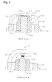
- the spark plug A assumes the form of a surface-gap spark plug and includes a center electrode 22; an insulator 23, which is disposed around the center electrode 22 such that an end portion of the center electrode 22 is exposed at the end surface thereof; and a ground electrode 24, positional relations thereof with an end portion of the insulator 23 and the end portion of the center electrode 22 being determined such that a spark discharge gap g is defined-between the ground electrode 24 and the end portion of the center electrode 22 and such that the discharge gap g enables creeping spark discharge across the surface of the end portion of the insulator 23.
- the spark plug A assumes the form of a so-called semi-surface-gap spark plug.
- the ground electrode 24 is disposed such that an end surface faces the side surface of the center electrode 22 while an end portion of the insulator 23 is disposed therebetween.
- the insulator 23 is formed from, for example, a sintered ceramic body, such as alumina or aluminum nitride.
- a hole portion (through-hole) 22d is formed in the insulator 23 in such a manner as to extend axially through the same.
- the center electrode 2 is fitted into the hole portion 23d.
- a metallic shell 27 is formed from a metal, such as low-carbon steel, and is formed into a cylindrical shape to thereby serve as a housing of the spark plug A.
- a male-threaded portion 26 is formed on the outer surface of the metallic shell 27 and is adapted to attach the spark plug 4 to a cylinder head.
- the insulator 23 is disposed such that an end portion thereof is disposed between the side surface of the center electrode 22 and a spark face 24a of the ground electrode 24.
- a noble-metal member of a Pt alloy or an Ir alloy is welded to the end surface of the center electrode 22 to thereby form a noble-metal spark portion 25.
- the end surface of the center electrode 22 (the noble-metal spark portion 25) is adjusted in position so as to be substantially flush with the end surface of the insulator 23.
- the spark plug 5 assumes the form of a so-called opposed-parallel-electrodes spark plug (hereinafter, may be called a spark plug B).
- the spark plug B includes a cylindrical metallic shell 37 (having a male-threaded portion 36 formed thereon); an insulator 33, which is fitted into the metallic shell 37 such that an end portion thereof projects from the same; a center electrode 32 having an end portion thereof tapered off and fitted into the hole portion 23d formed in the insulator 33 such that the end portion projects from the insulator 33; and a ground electrode 34 having one end connected to the metallic shell 37 through, for example, welding and having the other end bent such that the side surface thereof faces the end portion of the center electrode 32.
- a noble-metal member of a Pt alloy or an Ir alloy is welded to the end of the center electrode 32 to thereby form a noble-metal spark portion 35 and define a spark discharge gap g in cooperation with the ground electrode 34.
- a noble-metal spark portion 38 may be formed on the ground electrode 34 in opposition to the spark portion 35 of the center electrode 32, or may be omitted.
- two spark plugs A and B are attached to each of the cylinders 2A, 2B, 3B, and 3A such that the spark plug A assumes the form of a self-cleaning spark plug, whereby the spark plugs A and B become unlikely to suffer contamination such as soot accumulation.
- the spark plug A in the form of a self-cleaning spark plug reliably ignites a fuel-air gas mixture.
- the temperature of the engine rises sufficiently high, the contaminated spark plug B is cleaned; thus, a good condition of ignition can be maintained at all times.
- a discharge-inducing high voltage is applied to the spark plug A (4), which serves as a self-cleaning spark plug, such that the center electrode 22 assumes positive polarity.
- a spark discharge induced through application of a discharge-inducing high voltage to a spark plug such that a center electrode assumes positive polarity is called a positive-polarity discharge
- a spark discharge induced while the center electrode assumes negative polarity is called a negative-polarity discharge.
- the spark plug A (4) is also called a positive-polarity spark plug A.
- the nominal size of a male-threaded portion of a spark plug conforms to ISO2705 (M12) and ISO2704 (M10); thus, the size of the male-threaded portion may vary within a tolerance specified in the ISO standard.
- the present inventors conducted various studies and found that, as compared with a negative-polarity discharge, a positive-polarity discharge tends to cause an increase in the temperature of the center electrode 22 with a resultant slightly higher consumption rate of the electrode (noble-metal spark portion).
- a positive-polarity spark plug A whose metallic shell 27 has a male-threaded portion of the above-mentioned small size, a water jacket portion of a cylinder head can be expanded, thereby accelerating cooling of the center electrode 22 effected by means of the water-cooled cylinder head via the insulator 23 and the metallic shell 27 and thus effectively suppressing consumption of the electrode.
- a temperature rise of the insulator 23 is lessened, thereby further enhancing the effect of prevention of channeling to the insulator 23, which is primarily intended to be achieved through employment of a positive-polarity discharge.
- an effect peculiar to configuration of a multi-ignition cylinder is obtained. That is, even when a space for attachment of a spark plug to a cylinder head is limited, a plurality of spark plugs can be readily attached to the cylinder head through reduction in the nominal size of the male-threaded portion.
- spark plugs other than the self-cleaning spark plug each preferably assume the form of a negative-polarity spark plug B, to which a discharge-inducing high voltage is applied such that a center electrode assumes negative polarity.
- the negative-polarity spark plug B maintains a discharge similar to a glow-corona discharge in the vicinity of the tip end of the electrode and thus exhibits better igniting performance.
- the self-cleaning spark plug (A) which is of the creeping-discharge type, is of positive polarity and is slightly inferior in igniting performance to the negative-polarity spark plug (B), which is of the opposed-parallel-electrodes type.-However, because of excellent resistance to contamination, the self-cleaning spark plug (A) ignites a fuel-air gas mixture, in place of the contaminated negative-polarity spark plug (B), when the negative-polarity spark plug (B) is contaminated. Thus, the self-cleaning spark plug (A) can reliably ignite the fuel-air gas mixture at the initial stage of start-up of an engine, during which the temperature of the engine is low. In this case, the following secondary effect is yielded.
- the temperature of exhaust gas can be increased quickly, thereby accelerating activation of a catalyst, such as a three-way catalytic converter, for purification of exhaust gas.
- a catalyst such as a three-way catalytic converter
- the negative-polarity spark plug B When the engine temperature rises sufficiently high, the negative-polarity spark plug B is released from a contaminated state, whereby stable operation with few misfires can be realized through utilization of excellent igniting performance of the negative-polarity spark plug B. Particularly, in a lean-burn engine, which uses a lean fuel-air gas mixture and requires high energy for ignition, the negative-polarity spark plug B can reliably ignite the lean fuel-air gas mixture.
- the self-cleaning spark plug (A), which is a positive-polarity spark plug, and the negative-polarity spark plug B may be both operated at ignition timing.
- either the self-cleaning spark plug (A) or the negative-polarity spark plug B may be fired during a certain period of time which is determined according to operating conditions of an engine; for example, only the self-cleaning spark plug (A) is operated at an initial stage of start-up of an engine, during which contamination of a spark plug raises a problem, and only the negative-polarity spark plug B is operated after the engine temperature rises sufficiently high.
- the opposed-parallel-electrodes spark plug 5 used in the present embodiment can preferably serve as the negative-polarity spark plug B in terms of igniting performance.
- impartment of a tapering-off feature to an end portion of the center electrode 32 as shown in FIG. 2 is advantageous in generation of discharge sparks of high energy, since an electric field is apt to concentrate at a spark portion.
- Impartment of a tapering-off feature to an end portion of the center electrode 32 is also effective for prevention of misfire, since the end portion is less likely to absorb heat of combustion gas.
- the igniting performance of the opposed-parallel-electrodes spark plug 5 can be improved through slight expansion of the spark discharge gap g.
- an excessively wide spark discharge gap g involves a problem that, when a surface of the insulator 33 located within the metallic shell 37 is contaminated, discharge is apt to occur where the distance between the surface of the insulator 33 and the inner wall surface of the metallic shell 37 is less than the spark discharge gap g; i.e., a problem that contamination resistance is impaired.
- expansion of the spark discharge gap g is limited (for example, a typical conventional opposed-parallel-electrodes spark plug has a spark discharge gap of about 0.6 mm to 0.9 mm).
- the spark discharge gap g can be expanded to, for example, 1.0 mm to 1.3 mm, without the above-mentioned limitation.
- the ignition system 1 is applied to a multi-cylinder-type internal combustion engine including a plurality of multi-ignition cylinders, each of which is equipped with the positive-polarity spark plug A (self-cleaning spark plug (semi-surface-gap spark plug) 4) and the negative-polarity spark plug B (opposed-parallel-electrodes spark plug).
- Ignition coils 8A, 8B, 9B, and 9A constitute a high-voltage applicator.
- each of the ignition coils 8A, 8B, 9B, and 9A is connected to the corresponding positive-polarity spark plug A, whereas the negative end of the same secondary coil 11 is connected to the corresponding negative-polarity spark plug B.
- the two spark plugs A and B of different polarities share the same ignition coil, thereby simplifying the configuration of the ignition system.
- the present embodiment employs the first ignition coils 8A and 8B and the second ignition coils 9A and 9B.
- the positive end of the secondary coil 11 of the first ignition coil 8A (8B) is connected to the positive-polarity spark plug A of one multi-ignition cylinder (first cylinder 2A or 2B), whereas the negative end of the same secondary coil 11 is connected to the negative-polarity spark plug B of another multi-ignition cylinder (second cylinder 3A or 3B).
- the positive end of the secondary coil 11 of the second ignition coil 9A (9B) is connected to the positive-polarity spark plug A of the second cylinder 3A (3B), whereas the negative end of the same secondary coil 11 is connected to the negative-polarity spark plug B of the first cylinder 2A (2B).
- the four cylinders 2A, 2B, 3A, and 3B are connected to the same crankshaft (not shown) to thereby constitute a 4-stroke engine.
- the cylinders 2A and 3A constitute a pair of the above-mentioned first and second cylinders
- the cylinders 2B and 3B constitute a pair of the above-mentioned first and second cylinders.
- there is a phase difference of one stroke between the pairs As a result, the four cylinders are connected to the crankshaft while a phase difference of one stroke is present between the cylinders.
- Primary coils 10 of the corresponding ignition coils 8A, 8B, 9B, and 9A receive electricity from a battery 14 via an ignition switch 15 and are connected to an igniter 12.
- the igniter 12 includes contactless switch elements, which each include a power transistor, and a peripheral control circuit.
- the secondary coils 11 are connected to the corresponding spark plugs.
- the igniter 12 includes the contactless switch elements corresponding to the ignition coils 8A, 8B, 9B, and 9A. These contactless switch elements are opened individually at predetermined timing in response to individual opening instruction signals received from corresponding output ports (IG1 to IG4) of an electronic control unit (ECU) 13.
- ECU electronice control unit
- Each of the cylinders 2A, 2B, 3B, and 3A sequentially undergoes the intake stroke, the compression stroke, the expansion stroke, and the exhaust stroke in one cycle. Since there is a phase difference of two strokes between the first cylinders 2A and 2B and the second cylinders 3A and 3B, the ignition coils 8A, 8B, 9B, and 9A are operated so as to fire spark plugs attached to one of the first cylinders 2A and 2B and those attached to one of the second cylinders 3A and 3B for ignition of a fuel-air gas mixture and simultaneously to fire spark plugs attached to the other one of the first cylinders 2A and 2B and those attached to the other one of the secondary cylinders 3A and 3B at a phase which is 2 strokes apart from ignition timing; i.e., at timing different from the ignition timing. Accordingly, the spark plugs attached to the other cylinder of the first cylinders 2A and 2B and those attached to the other cylinder of the second cylinders 3A and 3B
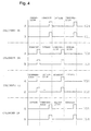
- FIG. 4 shows a timing chart of ignition instruction signals which are issued to the igniter 12 from the ECU 13 through the ports IG1 to IG4 (corresponding to the ignition coils 8A, 8B, 9B, and 9A).
- a rising edge from the L level to the H level serves as a trigger edge for an ignition instruction signal (i.e., the contactless switch element is opened so as to disconnect the primary coil 10, to thereby generate a discharge-inducing voltage at the corresponding spark plug via the secondary coil 11).
- the contactless switch element is opened so as to disconnect the primary coil 10, to thereby generate a discharge-inducing voltage at the corresponding spark plug via the secondary coil 11.
- ignition instruction signals associated with the spark plugs A and B are issued through the ports at two timings when one of the paired cylinders (2A or 3A and 2B or 3B) is in the compression stroke, whereas the other one of the paired cylinders is in the exhaust stroke.
- a first ignition instruction signal is issued when the first cylinder 2A is in the compression stroke, while the second cylinder 3A is in the exhaust stroke; and then a second ignition instruction signal is issued when the first cylinder 2A is in the exhaust stroke, while the second cylinder 3A is in the compression stroke.
- the first and second ignition instruction signals are issued synchronously with issuance of the first and second ignition instruction signals associated with the first ignition coil 8A.
- the same signal patterns are output for the paired cylinders 2B and 3B through the port IG2 (corresponding to the first ignition coil 8B) and the port IG3 (corresponding to the second ignition coil 9B) except that the phase differs by one stroke.
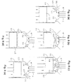
- FIG. 3 schematically shows the actions of the cylinders 2A, 2B, 3B, and 3A (which, hereinafter, are generically represented by a cylinder 51 as needed).
- (a) represents the intake stroke
- (b) represents the compression stroke
- (c) represents the expansion (explosion) stroke
- (d) represents the exhaust stroke.
- reference numeral 52 denotes a piston
- reference numeral 53 denotes a combustion chamber
- reference numeral 54 denotes an intake valve
- reference numeral 55 denotes an exhaust valve
- symbol MG denotes a fuel-air gas mixture
- symbol EG denotes an exhaust gas.
- the spark plugs 4 and 5 are each fired twice in one cycle.
- the spark plugs 4 and 5 are fired for ignition of MG at a substantial end stage of the compression stroke (for example, at a crank angle of 50° to 5° before a piston reaches the top dead center) as shown in (b) and are then fired again without contribution to ignition at the end stage of the exhaust stroke, which arises 2 strokes after the compression stroke, as shown in (d).
- the internal pressure of the combustion chamber 53 is low at the exhaust stroke, and the second firing breaks down at very low voltage. Thus, the second firing does not greatly accelerate consumption of an electrode.
- High voltage for inducing a spark discharge for ignition of a fuel-air gas mixture i.e., discharge-inducing high voltage
- discharge-inducing high voltage can be applied to at least two of a plurality of spark plugs attached to a multi-ignition cylinder at different timings.
- the internal pressure of a combustion chamber increases to some extent as a result of firing of one spark plug, the other spark plug is fired to thereby ignite the fuel-air gas mixture, thereby enhancing combustion efficiency.
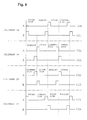
- FIG. 6 shows an example of ignition timing in this case.
- the ignition timing pattern of FIG. 6 is basically similar to that of FIG. 4 except that the positive-polarity spark plug A is first fired, and the negative-polarity spark plug B is fired a predetermined time later.
- the positive-polarity spark plug A which is resistant to contamination, is first fired to thereby perform initial ignition in a reliable condition.
- the negative-polarity spark plug B which exhibits good igniting performance, is fired so as to reliably complement ignition.
- the ECU 13 may be programmed such that the spark plugs are fired at different timings only when a predetermined engine condition is established, such as during low-speed rotation or under medium load.
- FIG. 5 schematically shows the action of the cylinder 51 in one cycle.
- (a) represents the intake stroke
- (b) represents the compression stroke
- (c) and (d) represent the expansion (explosion) stroke
- (e) and (f) represent the exhaust stroke.
- FIGS. 3 and 5 are denoted by common reference numerals.
- Discharge-inducing high voltage is applied to the spark plugs A (4) and B (5), which serve as a pair of spark plugs, for ignition of the fuel-air gas mixture in the following manner: one of the paired spark plugs; i.e., the positive-polarity spark plug A, is fired in the compression stroke as shown in (b), whereas the other one of the paired spark plugs; i.e., the negative-polarity spark plug B, is fired in the compression stroke at a predetermined timing immediately before the top dead center or in transition to the expansion stroke; for example, in the expansion stroke as shown in (c).
- combustion efficiency can further be enhanced.
- the fuel-air gas mixture contained in the combustion chamber 53 is combusted in such a manner that combustion propagates spatially from the spark generation position.
- combustion is apt to be delayed in a region distant from the spark generation position or a region behind another spark plug, potentially causing generation of unburnt gas components.
- the mounting position of the spark plug B, which performs the second ignition is determined in consideration of a region where combustion is apt to be delayed with respect to combustion initiated by the spark plug A, which performs the first ignition, thereby further enhancing combustion efficiency.
- the exhaust valve 55 may be opened before combustion is completed; as a result, in some cases, unburnt gas components present in the vicinity of the exhaust valve 55 may be discharged into an exhaust manifold.
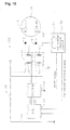
- an ignition system 200 of FIG. 14 is configured such that the positive and negative ends of the secondary coil 11 of an ignition coil 8 (9) provided for a cylinder 2 (3) are connected to the positive-polarity spark plug 4 and the negative-polarity spark plug 5, respectively, of the same cylinder 2 (3).
- the positive-polarity spark plugs 4 and the negative-polarity spark plug 5 are simultaneously fired at ignition timing.
- conceptually common features between the ignition system 200 of FIG. 14 and the ignition system 1 of FIG. 1 are denoted by common reference numerals, and redundant description thereof is omitted.
- the cylinders 2A, 2B, 3B, and 3A are each provided with a positive-polarity ignition coil 18-the positive end of the secondary coil 11 of which is connected to the positive-polarity spark plug A (4) ⁇ and a negative-polarity ignition coil 17-the negative end of the secondary coil 11 of which is connected to the negative-polarity spark plug B (5).
- An ignition system 100 of FIG. 7 is applied to an internal combustion engine assuming the same configuration as that of FIG. 1, but differs from the ignition system 1 of FIG. 1 in that the ignition coils 18 and 17 are provided for the spark plugs A and B on one-to-one correspondence and are independently operated or controlled via the igniter 12 by means of the individual ports IG1 to IG8 of the ECU 13.
- conceptually common features between the ignition system 100 of FIG. 7 and the ignition system 1 of FIG. 1 are denoted by common reference numerals, and redundant description thereof is omitted.
- FIG. 9 shows an example chart of ignition timing in this case. Since ignition instruction signals for all the positive-polarity spark plugs A and all the negative-polarity spark plugs B are independently output by means of the individual ports IG1 to IG8, the positive- and negative-polarity spark plugs A and B of each of the cylinders 2A, 2B, 3B, and 3A can be fired only at ignition timing. In contrast to the ignition system 200 of FIG. 14, the positive- and negative-polarity spark plugs A and B of the same cylinder can be fired at different timings. Also, either the positive-polarity spark plug A or the negative-polarity spark plug B can be fired during a certain period of time which is determined according to operating conditions of an engine.
- the above-described ignition systems can include a combustion condition judgment mechanism for judging the condition of combustion of a multi-ignition cylinder by the steps of applying a detection voltage to at least one of a plurality of spark plugs attached to the multi-ignition cylinder and detecting information regarding an ion current which flows between electrodes as a result of application of the detection voltage, or information indicative of the level of the ion current.
- a combustion condition judgment mechanism for judging the condition of combustion of a multi-ignition cylinder by the steps of applying a detection voltage to at least one of a plurality of spark plugs attached to the multi-ignition cylinder and detecting information regarding an ion current which flows between electrodes as a result of application of the detection voltage, or information indicative of the level of the ion current.
- the detection voltage is applied to the spark plug such that a center electrode assumes positive polarity, to thereby stably generate ion current.
- the spark plug used for detection and judgment of the condition of combustion may usually be used for generation of spark discharge and is used for detection of ion current only when the detection is needed.
- This arrangement contributes to improvement in igniting performance and more effective use of spark plugs attached to a cylinder.
- a positive-polarity spark plug which is a self-cleaning spark plug, preferably assumes the role of detection and judgment of the condition of combustion.
- the above-mentioned function is preferably imparted to, for example, the ignition system 100 of FIG. 7.
- an ion current detection circuit 70 must be additionally installed in a line connected to the positive-polarity spark plug A.
- the ion current detection circuit 70 is an essential component of the combustion condition judgment mechanism and includes a step-up coil element 131 and a current waveform processing circuit 134 as shown in FIG. 11.
- the step-up coil element 131 assumes a structure similar to that of an ignition coil.
- One end of a primary coil 131 a receives electricity from a battery 14, whereas the other end of the primary coil 131a is grounded via a transistor 132, which serves as a switching element.
- One end of a secondary coil 132b is connected to an end of the secondary coil 11 of a positive-polarity ignition coil 18' which is not connected to the positive-polarity spark plug A, whereas the other end of the secondary coil 131b is grounded.
- the transistor 132 is turned on and off in order to energize and de-energize the primary coil 131a to thereby generate a detection voltage in the secondary coil 132b.
- the thus-generated detection voltage is output to the spark plug A via the secondary coil 11 of the ignition coil 18'.
- An ion current which is generated in the spark plug A as a result of application of the detection voltage to the spark plug A is input to the current waveform processing circuit 134, which is disposed on a line branching off from an output line of the secondary coil 131b.
- the waveform processing circuit 134 converts the ion current to a digital-waveform signal, which is an ion current waveform signal, and outputs the signal to the ECU 13.
- Reference numeral 133 denotes a diode adapted to prevent backflow of an ion current output to the secondary coil 131b.
- the ECU 13 outputs an instruction to initiate a spark discharge from a port IG2, to thereby cause, via the igniter 12, the positive-polarity spark plug B of each cylinder to initiate a spark discharge.
- the ECU 13 usually outputs an instruction to the positive-polarity spark plug A from a port IG1 so as to cause, via the igniter 12, the positive-polarity spark plug A to initiate a spark discharge under positive polarity.
- the ECU 13 stops outputting the instruction to initiate a spark discharge (that is, a spark discharge is not performed in one cycle) and outputs a reset signal to the ion current detection circuit 70 from the port IG1.
- the ion current detection circuit 70 Upon reception of the reset signal, the ion current detection circuit 70 applies a detection voltage to the positive-polarity spark plug A and detects an ion current. The ion current detection circuit 70 returns a waveform signal indicative of the ion current to the-ECU 13 via the current waveform processing circuit 134. The ECU 13 analyzes the received waveform signal to thereby detect various data.
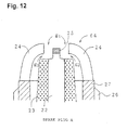
- Examples of a self-cleaning spark plug having a structure suited for generation of an ion current include the semi-surface-gap spark plug 4 of FIG. 2 and an intermittent-surface-gap spark plug 64 shown in FIG. 12.
- the end surface of the ground electrode 24 faces the side surface of the center electrode 22; thus, a broad electrode area can be attained to thereby improve sensitivity in detection of an ion current waveform signal.
- an end portion of the insulator 23 is not projected into the space between the outer circumferential surface of an end portion of the center electrode 22 and the end surface of the ground electrode 24.
- the end portion of the center electrode 22 is tapered off, and a noble-metal spark portion 25 is joined to the end surface of the end portion.
- the center electrode 22 is disposed such that the end portion thereof projects from the insulator 23.
- the cylindrical metallic shell 27 is disposed in such a manner as to surround the insulator 23.
- a base end of the ground electrode 24 is joined to an end portion of the metallic shell 27, whereas a free end portion of the ground electrode 24 is bent toward the center electrode 22 such that the end surface thereof faces the side surface of the end portion of the center electrode 22 to thereby define a first gap gl and such that the inner wall surface of the free end portion of the ground electrode 24 faces the end surface of the insulator 23 to thereby define a second gap g2 narrower than the first gap g1.
- the thus-configured intermittent-surface-gap spark plug 64 can be used as a self-cleaning spark plug even in the ignition system 1 of FIG. 1, which does not involve detection of an ion current.
- FIGS. 13 (a) and 13 (b) in the case where the intermittent-surface-gap spark plug 64, which serves as a positive-polarity spark plug, is caused to detect an ion current when the negative-polarity spark plug B (5) initiates a spark discharge, a detected ion current waveform reflects the condition of combustion of a fuel-air gas mixture, which is ignited and combusted by means of a spark discharge initiated by the negative-polarity spark plug B (5).
- FIG. 13 (c) represents a waveform as observed during normal combustion. The waveform includes a peak corresponding to a shock wave induced by combustion/explosion. When knocking occurs, the waveform is disturbed as shown in FIG. 13 (c).
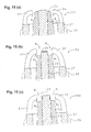
- FIGS. 15 and 16 show further examples of a self-cleaning spark plug applicable to the present invention (features common to FIGS. 15 and 16 and FIG. 2 or 12 are denoted by common reference numerals).
- FIG. 15 (a) shows a semi-surface-gap spark plug 104, in which an end portion of the center electrode 22 is projected from the insulator 23.
- FIG. 15 (b) shows an intermittent-surface-gap spark plug 164, in which an end portion of the center electrode is not tapered off.
- FIG. 15 (c) shows an intermittent-surface-gap spark plug 264, in which a band-shaped noble-metal spark portion 125 is wound on the circumferential surface of a projected end portion of the center electrode 22.
- FIG. 15 (a) shows a semi-surface-gap spark plug 104, in which an end portion of the center electrode 22 is projected from the insulator 23.
- FIG. 15 (b) shows an intermittent-surface-gap spark plug 164, in which an
- FIG. 16 shows an opposed-parallel-electrodes spark plug 65 which serves as a self-cleaning spark plug.
- An end portion of a through-hole h formed in the insulator 33 is tapered such that the diameter thereof decreases toward the end thereof, thereby forming a diameter-reduced portion h'.
- the center electrode 32 is inserted into the through-hole h such that a diameter-reduced portion thereof assuming a shape corresponding to that of the diameter-reduced portion h' is fitted into the diameter-reduced portion h' in such a manner as to align the end surface of the center electrode 32 with the end surface of the insulator 33.
Landscapes
- Engineering & Computer Science (AREA)
- Chemical & Material Sciences (AREA)
- Combustion & Propulsion (AREA)
- Mechanical Engineering (AREA)
- General Engineering & Computer Science (AREA)
- Physics & Mathematics (AREA)
- Plasma & Fusion (AREA)
- Ignition Installations For Internal Combustion Engines (AREA)
- Spark Plugs (AREA)
- Electrical Control Of Ignition Timing (AREA)
Abstract
Description
Claims (19)
- An ignition system for an internal combustion engine having a multi-ignition cylinder equipped with a plurality of spark plugs serving as ignition sources, characterized in that at least one of the spark plugs is a self-cleaning spark plug capable of removing, by means of discharge spark, contaminant adhering to an insulator surface facing a spark discharge gap of said self-cleaning spark plug.
- An ignition system for an internal combustion engine according to claim 1, wherein said self-cleaning spark plug assumes the form of a surface-gap spark plug comprising:a center electrode;an insulator, which is disposed around said center electrode such that an end portion of said center electrode is exposed at an end surface of said insulator; anda ground electrode,wherein the relative positions of said ground electrode, an end portion of said insulator and the'end portion of said center electrode are determined such that a spark discharge gap is defined between said ground electrode and the end portion of said center electrode and such that the discharge gap enables creeping spark discharge across the surface of the end portion of said insulator.
- An ignition system for an internal combustion engine according to claim 1 or 2, further comprising a high-voltage applicator for applying a discharge-inducing high voltage, for inducing a spark discharge, between the center electrode and the ground electrode of said self-cleaning spark plug such that the center electrode assumes positive polarity.
- An ignition system for an internal combustion engine according to claim 3, wherein a male-threaded portion of said self-cleaning spark plug for mounting said self-cleaning spark plug to said cylinder assumes a nominal size of M12 or M10.
- An ignition system for an internal combustion engine according to claim 4, wherein said self-cleaning spark plug among the plurality of spark plugs attached to the same multi-ignition cylinder serves as a positive-polarity spark plug, to which said high-voltage applicator applies the discharge-inducing high voltage such that the center electrode assumes positive polarity, and the spark plugs other than said self-cleaning spark plug serve as negative-polarity spark plugs, to each of which said high-voltage applicator applies the discharge-inducing high voltage such that the center electrode assumes negative polarity.
- An ignition system for an internal combustion engine according to claim 5, wherein said negative-polarity spark plugs each assume a form in which the end surface of a center electrode faces the side surface of a ground electrode.
- An ignition system for an internal combustion engine according to any one of claims 1 to 6, further comprising a high-voltage applicator for applying a discharge-inducing high voltage for igniting a fuel-air gas mixture, to at least two spark plugs among the plurality of spark plugs attached to said multi-ignition cylinder at different points of timing.
- An ignition system for an internal combustion engine according to claim 7, wherein said multi-ignition cylinder is equipped with a positive-polarity spark plug, to which a discharge-inducing high voltage is applied such that a center electrode assumes positive polarity, and a negative-polarity spark plug, to which a discharge-inducing high voltage is applied such that a center electrode assumes negative polarity and wherein said high-voltage applicator applies the discharge-inducing high voltage to the positive- and negative-polarity spark plugs at different points of timing such that the positive-polarity spark plug is first fired.
- An ignition system for an internal combustion engine according to claim 8, wherein said multi-ignition cylinder is a 4-stroke cylinder and wherein said high-voltage applicator applies the discharge-inducing high-voltage to a pair of spark plugs attached to the 4-stroke cylinder for igniting a fuel-air gas mixture such that one spark plug is fired during a compression stroke immediately before the 4-stroke cylinder reaches a top dead center, whereas the other spark plug is fired during an expansion stroke immediately after the 4-stroke cylinder reaches the top dead center.
- An ignition system for an internal combustion engine according to any one of claims 1 to 9, wherein the internal combustion engine includes a plurality of multi-ignition cylinders, to each of which are attached a positive-polarity spark plug, to which a discharge-inducing high voltage is applied such that a center electrode assumes positive polarity, and a negative-polarity spark plug, to which a discharge-inducing high voltage is applied such that a center electrode assumes negative polarity; and
wherein an ignition coil of a high-voltage applicator is configured such that a positive end of a secondary coil is connected to a positive-polarity spark plug, whereas a negative end of the same secondary coil is connected to a negative-polarity spark plug. - An ignition system for an internal combustion engine according to claim 10, the internal combustion engine assuming the form of a multi-cylinder-type internal combustion engine including a plurality of multi-ignition cylinders,
wherein said high-voltage applicator comprises components, for generating the discharge-inducing high voltage, which in turn comprise:a first ignition coil configured such that a positive end of a secondary coil is connected to a positive-polarity spark plug of one (hereinafter referred to as a first cylinder) of said multi-ignition cylinders, whereas a negative end of the secondary coil is connected to a negative-polarity spark plug of another one (hereinafter referred to as a second cylinder) of said multi-ignition cylinders, anda second ignition coil configured such that a positive end of a secondary coil is connected to a positive-polarity spark plug of said second cylinder, whereas a negative end of the secondary coil is connected to a negative-polarity spark plug of said first cylinder. - An ignition system for an internal combustion engine according to claim 11, wherein said first cylinder and said second cylinder are 4-stroke cylinders operating synchronously while a phase difference of two strokes is maintained therebetween and wherein said first and second ignition coils each cause a spark plug attached to one of said first and second cylinders to be fired for ignition and simultaneously cause a spark plug attached to the other one to be fired at a phase which is substantially two strokes apart from the ignition timing.
- An ignition system for an internal engine according to any one of claims 1 to 9, wherein the internal combustion engine assumes the form of a multi-cylinder-type internal combustion engine including a plurality of multi-ignition cylinders, to each of which are attached a positive-polarity spark plug, to which a discharge-inducing high voltage is applied such that a center electrode assumes positive polarity, and a negative-polarity spark plug, to which a discharge-inducing high voltage is applied such that a center electrode assumes negative polarity; and
wherein a high-voltage applicator comprises components for generating the discharge-inducing high voltage which is provided for each of the multi-ignition cylinders and which in turn comprise a positive-polarity ignition coil and a negative-polarity ignition coil, the positive-polarity ignition coil being configured such that a positive end of a secondary coil is connected to a positive-polarity spark plug, the negative-polarity ignition coil being configured such that a negative end of a secondary coil is connected to a negative-polarity spark plug. - An ignition system for an internal combustion engine according to claim 13, wherein said positive-polarity spark plug and said negative-polarity spark plug are fired only at the ignition timing in each of the multi-ignition cylinders.
- An ignition system for an internal combustion engine according to any one of claims 1 to 14, further comprising a combustion condition judgment mechanism for judging the condition of combustion of said multi-ignition cylinder by the steps of applying a detection voltage to at least one of the plurality of spark plugs attached to said multi-ignition cylinder and detecting information regarding an ion current which flows between said electrodes as a result of application of the detection voltage, or information indicative of the level of the ion current.
- An ignition system for an internal combustion engine according to claim 15, wherein the detection voltage is applied to said spark plug such that a center electrode assumes positive polarity.
- An ignition system for an internal combustion engine having a plurality of multi-ignition cylinders, each equipped with a plurality of spark plugs serving as ignition sources, characterized in that:said multi-ignition cylinders are each equipped with a positive-polarity spark plug, to which a discharge-inducing high voltage is applied such that a center electrode assumes positive polarity, and a negative-polarity spark plug, to which a discharge-inducing high voltage is applied such that a center electrode assumes negative polarity; andan ignition coil for generating the discharge-inducing high voltage is configured such that a positive end of a secondary coil is connected to the positive-polarity spark plug, whereas a negative end of the same secondary coil is connected to the negative-polarity spark plug.
- An ignition system for an internal combustion engine according to claim 17, wherein the positive-polarity spark plug and the negative-polarity spark plug which are connected to the same secondary coil are attached to different multi-ignition cylinders.
- An ignition system for an internal combustion engine according to claim 17, wherein the positive-polarity spark plug and the negative-polarity spark plug which are connected to the same secondary coil are attached to the same multi-ignition cylinder.
Applications Claiming Priority (2)
| Application Number | Priority Date | Filing Date | Title |
|---|---|---|---|
| JP2000048232A JP3387039B2 (en) | 2000-02-24 | 2000-02-24 | Ignition system for internal combustion engine |
| JP2000048232 | 2000-02-24 |
Publications (3)
| Publication Number | Publication Date |
|---|---|
| EP1134409A2 true EP1134409A2 (en) | 2001-09-19 |
| EP1134409A3 EP1134409A3 (en) | 2004-04-07 |
| EP1134409B1 EP1134409B1 (en) | 2010-03-31 |
Family
ID=18570353
Family Applications (1)
| Application Number | Title | Priority Date | Filing Date |
|---|---|---|---|
| EP01301674A Expired - Lifetime EP1134409B1 (en) | 2000-02-24 | 2001-02-23 | Ignition system for internal combustion engine |
Country Status (4)
| Country | Link |
|---|---|
| US (1) | US6536406B2 (en) |
| EP (1) | EP1134409B1 (en) |
| JP (1) | JP3387039B2 (en) |
| DE (1) | DE60141661D1 (en) |
Cited By (1)
| Publication number | Priority date | Publication date | Assignee | Title |
|---|---|---|---|---|
| EP1956232A4 (en) * | 2005-11-30 | 2013-01-09 | Toyota Motor Co Ltd | INTERNAL COMBUSTION IGNITION DEVICE |
Families Citing this family (21)
| Publication number | Priority date | Publication date | Assignee | Title |
|---|---|---|---|---|
| US6647974B1 (en) * | 2002-09-18 | 2003-11-18 | Thomas L. Cowan | Igniter circuit with an air gap |
| JP2004247571A (en) | 2003-02-14 | 2004-09-02 | Diamond Electric Mfg Co Ltd | Ignition device for internal combustion engine |
| JP4089484B2 (en) * | 2003-03-31 | 2008-05-28 | 株式会社デンソー | Ignition device for internal combustion engine |
| JP2005339981A (en) * | 2004-05-27 | 2005-12-08 | Nissan Motor Co Ltd | Spark plug |
| DE102005006354A1 (en) * | 2005-02-11 | 2006-08-24 | Robert Bosch Gmbh | Ignition system for an internal combustion engine |
| US7665452B2 (en) * | 2006-03-17 | 2010-02-23 | Ford Global Technologies, Llc | First and second spark plugs for improved combustion control |
| BRPI0711951B1 (en) * | 2006-05-18 | 2018-12-11 | Ambixtra (Pty) Ltd. | method for monitoring at least one parameter associated with a gaseous substance in a chamber without igniting the gaseous substance |
| JP4862756B2 (en) * | 2007-06-14 | 2012-01-25 | マツダ株式会社 | Engine knocking detection device |
| JP2009019612A (en) * | 2007-07-13 | 2009-01-29 | Isuzu Motors Ltd | Spark plug system |
| US7677230B2 (en) * | 2007-10-30 | 2010-03-16 | Ford Global Technologies, Llc | Internal combustion engine with multiple spark plugs per cylinder and ion current sensing |
| EP2058512A3 (en) | 2007-11-07 | 2015-05-20 | Mazda Motor Corporation | Upper structure of engine |
| US7992542B2 (en) * | 2008-03-11 | 2011-08-09 | Ford Global Technologies, Llc | Multiple spark plug per cylinder engine with individual plug control |
| US8176893B2 (en) * | 2008-08-30 | 2012-05-15 | Ford Global Technologies, Llc | Engine combustion control using ion sense feedback |
| JP4884516B2 (en) * | 2009-11-19 | 2012-02-29 | 三菱電機株式会社 | Ignition control device for internal combustion engine |
| DE102010045044B4 (en) * | 2010-06-04 | 2012-11-29 | Borgwarner Beru Systems Gmbh | A method for igniting a fuel-air mixture of a combustion chamber, in particular in an internal combustion engine, by generating a corona discharge |
| DE102013108705B4 (en) * | 2013-08-12 | 2017-04-27 | Borgwarner Ludwigsburg Gmbh | Corona ignition system and method for controlling a corona ignition device |
| DE102019126831B4 (en) * | 2018-10-11 | 2025-01-30 | Federal-Mogul Ignition Llc | spark plug |
| US10947948B1 (en) * | 2020-02-12 | 2021-03-16 | Ford Global Technologies, Llc | Systems and methods for ignition coil multiplexing in a pre-chamber system |
| JP7743335B2 (en) * | 2022-02-28 | 2025-09-24 | 三菱重工エンジン&ターボチャージャ株式会社 | internal combustion engine |
| CN116428089B (en) * | 2023-03-27 | 2024-07-05 | 重庆长安汽车股份有限公司 | Engine ignition control device and car |
| CN119393272A (en) * | 2024-12-31 | 2025-02-07 | 浙江辉波蕾汽车部件有限公司 | Automobile ignition coil |
Citations (2)
| Publication number | Priority date | Publication date | Assignee | Title |
|---|---|---|---|---|
| US2025203A (en) | 1933-03-27 | 1935-12-24 | H B Motor Corp | Combustion engine |
| EP0899840A1 (en) | 1997-09-01 | 1999-03-03 | Ngk Spark Plug Co., Ltd | Spark plug and an internal combustion engine igniting system using the same |
Family Cites Families (12)
| Publication number | Priority date | Publication date | Assignee | Title |
|---|---|---|---|---|
| US2899585A (en) | 1959-08-11 | dollenberg | ||
| US3964454A (en) * | 1973-07-06 | 1976-06-22 | Hitachi, Ltd. | Differential ignition timing firing control system |
| JPS53123731A (en) * | 1977-04-06 | 1978-10-28 | Ngk Spark Plug Co Ltd | Ignition system |
| JPS5428917A (en) * | 1977-08-08 | 1979-03-03 | Nissan Motor Co Ltd | Two-point ignition engine |
| JPS55112870A (en) * | 1979-02-22 | 1980-09-01 | Nippon Soken Inc | Igniting device for engine |
| JPS59173558A (en) | 1983-03-21 | 1984-10-01 | Nippon Soken Inc | Igniter of multicylinder internal-combustion engine |
| JPH0260081A (en) | 1988-08-25 | 1990-02-28 | Ngk Spark Plug Co Ltd | Spark plug for internal combustion engine and manufacture thereof |
| JPH04140478A (en) | 1990-10-01 | 1992-05-14 | Mitsubishi Electric Corp | Ignition device for internal combustion engine |
| JPH0633857A (en) | 1992-07-13 | 1994-02-08 | Mitsubishi Electric Corp | Ignitor for internal combustion engine |
| JPH06221257A (en) | 1993-01-27 | 1994-08-09 | Mitsubishi Electric Corp | Internal combustion engine ignition device |
| JPH084641A (en) | 1994-06-21 | 1996-01-09 | Mazda Motor Corp | Multi-point ignition engine |
| WO1997048905A1 (en) * | 1996-06-20 | 1997-12-24 | Mecel Ab | Method for ignition control in combustion engines |
-
2000
- 2000-02-24 JP JP2000048232A patent/JP3387039B2/en not_active Expired - Fee Related
-
2001
- 2001-02-23 US US09/790,868 patent/US6536406B2/en not_active Expired - Fee Related
- 2001-02-23 EP EP01301674A patent/EP1134409B1/en not_active Expired - Lifetime
- 2001-02-23 DE DE60141661T patent/DE60141661D1/en not_active Expired - Lifetime
Patent Citations (2)
| Publication number | Priority date | Publication date | Assignee | Title |
|---|---|---|---|---|
| US2025203A (en) | 1933-03-27 | 1935-12-24 | H B Motor Corp | Combustion engine |
| EP0899840A1 (en) | 1997-09-01 | 1999-03-03 | Ngk Spark Plug Co., Ltd | Spark plug and an internal combustion engine igniting system using the same |
Cited By (1)
| Publication number | Priority date | Publication date | Assignee | Title |
|---|---|---|---|---|
| EP1956232A4 (en) * | 2005-11-30 | 2013-01-09 | Toyota Motor Co Ltd | INTERNAL COMBUSTION IGNITION DEVICE |
Also Published As
| Publication number | Publication date |
|---|---|
| JP2001234842A (en) | 2001-08-31 |
| JP3387039B2 (en) | 2003-03-17 |
| EP1134409B1 (en) | 2010-03-31 |
| US20010017125A1 (en) | 2001-08-30 |
| DE60141661D1 (en) | 2010-05-12 |
| EP1134409A3 (en) | 2004-04-07 |
| US6536406B2 (en) | 2003-03-25 |
Similar Documents
| Publication | Publication Date | Title |
|---|---|---|
| EP1134409B1 (en) | Ignition system for internal combustion engine | |
| EP1801413B1 (en) | Plasma-jet spark plug control method and device | |
| EP0652363B1 (en) | Engine ignition and control system | |
| JPH07166947A (en) | Detecting method of self-ignition in combustion cylinder for spark-discharge ignition internal combustion engine | |
| JP6445928B2 (en) | Ignition device for internal combustion engine | |
| JP2020159355A (en) | Spark plug for internal combustion engine and internal combustion engine equipped with it | |
| JP4981869B2 (en) | Combustion state detection device for internal combustion engine | |
| EP0652365B1 (en) | Misfire detection method | |
| EP0652364B1 (en) | Load detection method | |
| US5447136A (en) | Ignition system for internal combustion engines | |
| JP2009203864A (en) | Combustion state detection device and ignition control system | |
| JP4968203B2 (en) | Plasma ignition device | |
| JP3695954B2 (en) | Control device for spark ignition type direct injection internal combustion engine | |
| KR100199807B1 (en) | Spark plug with mans preventing from precipitating carbon | |
| US20230327407A1 (en) | Ignition device | |
| JP4185848B2 (en) | Manufacturing method of spark plug | |
| KR100588074B1 (en) | Spark Plugs for Internal Combustion Engines | |
| JP2003013832A (en) | Misfire detection device for internal combustion engine | |
| JP7102151B2 (en) | Ignition system for internal combustion engine | |
| KR20010027162A (en) | Ignition circuit for protecting knocking | |
| KR19980020079A (en) | Anti-knocking device for automobile engine | |
| KR19980034338A (en) | Method for preventing abnormal consumption of engine oil due to excessive intake negative pressure in a vehicle | |
| JP2008258077A (en) | Spark plug | |
| JPS6161972A (en) | Ignition device of internal-combustion engine | |
| JPH10223351A (en) | Spark plug for knocking detection and knocking detection system using the same |
Legal Events
| Date | Code | Title | Description |
|---|---|---|---|
| PUAI | Public reference made under article 153(3) epc to a published international application that has entered the european phase |
Free format text: ORIGINAL CODE: 0009012 |
|
| AK | Designated contracting states |
Kind code of ref document: A2 Designated state(s): AT BE CH CY DE DK ES FI FR GB GR IE IT LI LU MC NL PT SE TR |
|
| AX | Request for extension of the european patent |
Free format text: AL;LT;LV;MK;RO;SI |
|
| PUAL | Search report despatched |
Free format text: ORIGINAL CODE: 0009013 |
|
| AK | Designated contracting states |
Kind code of ref document: A3 Designated state(s): AT BE CH CY DE DK ES FI FR GB GR IE IT LI LU MC NL PT SE TR |
|
| AX | Request for extension of the european patent |
Extension state: AL LT LV MK RO SI |
|
| RIC1 | Information provided on ipc code assigned before grant |
Ipc: 7H 01T 13/52 B Ipc: 7F 02P 15/02 A Ipc: 7F 02P 15/08 B |
|
| 17P | Request for examination filed |
Effective date: 20040708 |
|
| 17Q | First examination report despatched |
Effective date: 20041019 |
|
| AKX | Designation fees paid |
Designated state(s): DE FR GB IT |
|
| 17Q | First examination report despatched |
Effective date: 20041213 |
|
| GRAP | Despatch of communication of intention to grant a patent |
Free format text: ORIGINAL CODE: EPIDOSNIGR1 |
|
| GRAS | Grant fee paid |
Free format text: ORIGINAL CODE: EPIDOSNIGR3 |
|
| GRAA | (expected) grant |
Free format text: ORIGINAL CODE: 0009210 |
|
| AK | Designated contracting states |
Kind code of ref document: B1 Designated state(s): DE FR GB IT |
|
| REG | Reference to a national code |
Ref country code: GB Ref legal event code: FG4D |
|
| REF | Corresponds to: |
Ref document number: 60141661 Country of ref document: DE Date of ref document: 20100512 Kind code of ref document: P |
|
| PLBE | No opposition filed within time limit |
Free format text: ORIGINAL CODE: 0009261 |
|
| STAA | Information on the status of an ep patent application or granted ep patent |
Free format text: STATUS: NO OPPOSITION FILED WITHIN TIME LIMIT |
|
| 26N | No opposition filed |
Effective date: 20110104 |
|
| PG25 | Lapsed in a contracting state [announced via postgrant information from national office to epo] |
Ref country code: IT Free format text: LAPSE BECAUSE OF FAILURE TO SUBMIT A TRANSLATION OF THE DESCRIPTION OR TO PAY THE FEE WITHIN THE PRESCRIBED TIME-LIMIT Effective date: 20100331 |
|
| GBPC | Gb: european patent ceased through non-payment of renewal fee |
Effective date: 20110223 |
|
| PG25 | Lapsed in a contracting state [announced via postgrant information from national office to epo] |
Ref country code: GB Free format text: LAPSE BECAUSE OF NON-PAYMENT OF DUE FEES Effective date: 20110223 |
|
| REG | Reference to a national code |
Ref country code: FR Ref legal event code: PLFP Year of fee payment: 16 |
|
| REG | Reference to a national code |
Ref country code: FR Ref legal event code: PLFP Year of fee payment: 17 |
|
| PGFP | Annual fee paid to national office [announced via postgrant information from national office to epo] |
Ref country code: DE Payment date: 20170214 Year of fee payment: 17 Ref country code: FR Payment date: 20170112 Year of fee payment: 17 |
|
| REG | Reference to a national code |
Ref country code: DE Ref legal event code: R119 Ref document number: 60141661 Country of ref document: DE |
|
| REG | Reference to a national code |
Ref country code: FR Ref legal event code: ST Effective date: 20181031 |
|
| PG25 | Lapsed in a contracting state [announced via postgrant information from national office to epo] |
Ref country code: DE Free format text: LAPSE BECAUSE OF NON-PAYMENT OF DUE FEES Effective date: 20180901 |
|
| PG25 | Lapsed in a contracting state [announced via postgrant information from national office to epo] |
Ref country code: FR Free format text: LAPSE BECAUSE OF NON-PAYMENT OF DUE FEES Effective date: 20180228 |