EP1134404B1 - Device for the treatment of fuel in thermal engines - Google Patents
Device for the treatment of fuel in thermal engines Download PDFInfo
- Publication number
- EP1134404B1 EP1134404B1 EP99956037A EP99956037A EP1134404B1 EP 1134404 B1 EP1134404 B1 EP 1134404B1 EP 99956037 A EP99956037 A EP 99956037A EP 99956037 A EP99956037 A EP 99956037A EP 1134404 B1 EP1134404 B1 EP 1134404B1
- Authority
- EP
- European Patent Office
- Prior art keywords
- fuel
- cylindrical
- pipe
- cups
- magnetic
- Prior art date
- Legal status (The legal status is an assumption and is not a legal conclusion. Google has not performed a legal analysis and makes no representation as to the accuracy of the status listed.)
- Expired - Lifetime
Links
Images



Classifications
-
- F—MECHANICAL ENGINEERING; LIGHTING; HEATING; WEAPONS; BLASTING
- F02—COMBUSTION ENGINES; HOT-GAS OR COMBUSTION-PRODUCT ENGINE PLANTS
- F02M—SUPPLYING COMBUSTION ENGINES IN GENERAL WITH COMBUSTIBLE MIXTURES OR CONSTITUENTS THEREOF
- F02M27/00—Apparatus for treating combustion-air, fuel, or fuel-air mixture, by catalysts, electric means, magnetism, rays, sound waves, or the like
- F02M27/04—Apparatus for treating combustion-air, fuel, or fuel-air mixture, by catalysts, electric means, magnetism, rays, sound waves, or the like by electric means, ionisation, polarisation or magnetism
- F02M27/045—Apparatus for treating combustion-air, fuel, or fuel-air mixture, by catalysts, electric means, magnetism, rays, sound waves, or the like by electric means, ionisation, polarisation or magnetism by permanent magnets
Definitions
- the present invention is intended to disclose a method of treating fuel upon its admittance to internal combustion engines, in order to improve various characteristics of their performance.
- the device of the present invention has been designed on the basis of investigations carried out by the inventor in order to reduce environmental pollution caused by internal combustion engines and to improve their performance, with the aim of reducing consumption.
- the application of the present invention is intended to facilitate compliance with the new standards of the European Economic Community relating to pollution.
- the device of the present invention acts by modifying the chemical-physical properties of the molecules of the fluids (petrol, gas oil and mixtures), ensuring a more uniform mixture between the atoms of the fluid and atmospheric oxygen, giving rise to optimal combustion.
- the basis of the present invention consists in causing the fluid, as it flows through the interior of the device, to be surrounded by a strong magnetic field which favours weakening of the mutual magnetic attraction of the molecules and breakage of the weak magnetic connection, destroying the molecules and transforming them into atoms.
- the atoms are separated from one another, following an orderly course, permitting improved diffusion of the oxygen, improving combustion, and reducing the emission of CO in favour of CO 2 , reducing the formation of NOx, as well as the emission of residues and the deposition of carbonaceous substances.
- a notable reduction in consumption, a cleaner engine, and a considerable reduction in polluting emissions are achieved.
- the device of the present invention is intended to be located along the path of the fuel to be treated, obliging the fuel to pass through the strong magnetic field, which is created inside the device in a direction perpendicular to the direction of movement of the fuel.
- the improvement of the mixture between the oxygen and the fuel atoms favours the combustion process, leading to a series of advantages, amongst which the following stand out:
- the device of the present invention comprises, basically, a cylindrical assembly carrying two or more magnetic masses in the form of elongate bars between which the fuel pipe extends towards the engine, the assembly being surrounded by a first tubular element which is particularly appropriate in the preferred case in which the body supporting the polar masses is formed by two elongate elements coupled with one another in a manner such that both together complete an enveloping cylindrical shape, the elements being coupled along a flat surface or along stepped surfaces, and having housings for receiving the magnetic masses.
- An outer surrounding body and guide for the fuel pipe is preferably composed of two elements in the form of long cylindrical cups which face one another, forming a cylindrical body closed at its ends by end portions having holes through which the fuel pipe can extend.
- An outer protective and insulating envelope is constituted principally by a synthetic resin envelope fixed to the ends of the surrounding body.
- US patent 4995425 discloses a magnetic fluid conditioner with magnetic masses applied onto right angle laminar parts which surround a central conduit for the fluid.
- the invention is applicable in the household to prevent the incrustation of calcium salts and in the industry on conduits transmitting crude oil.
- said document does not disclose nor suggest the use of a carrying body with cavitites to receive the magnetic masses combined with multiple surrounding bodies for the treatment of fuel in internal combustion engines.
- Figure 1 is an external plan view of the device.
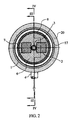
- Figure 2 is a cross-section of the device.
- Figure 3 is a longitudinal section through a device, showing the pipe which extends longitudinally through it.
- Figure 4 is a longitudinal section which includes one of the magnetic masses.
- the device of the present invention comprises two or more elongate, high-remanence magnetic masses 1 and 2 disposed adjacent a fuel-supply pipe 3 which extends towards the engine, for example, via an outlet pipe 4, having entered through the other end of the device, via a pipe 5, Figure 1.
- the magnetic masses are enclosed in a carrying body 6 which surrounds them completely and which may be constituted, for example, by two elements facing one another along the median plane 7 of the body.
- the shape of the carrying body 6, as well as that of the magnetic masses 1 and 2 may vary, since it is not essential for the operation of the device. Thus, for example, instead of having the cylindrical shape shown, it may have a right-angled parallelepipedal shape, a prismatic shape, etc.
- a retaining body 8 surrounds the body 6 carrying the magnetic masses and in turn is housed in an assembly constituted by two symmetrical elements 9 and 10 which are in the form of elongate, cylindrical cups with respective end portions in which stumps 11 and 12 are formed, the stumps 11 and 12 having through-holes 13 and 14 through which the fuel pipe 3 can extend.
- the said elements 9 and 10 face one another and house the ends of the surrounding body 8, having annular guide grooves 15 and 16 for receiving the ends of the surrounding body 8.
- a further cylindrical surrounding body 17 Arranged over the assembly formed by two bodies 9 and 10 is a further cylindrical surrounding body 17 in which caps 18 and 19 are fitted, the whole being included inside an envelope of insulating synthetic resin 20 which is introduced into grooves 21 and 22 of the stumps 11 and 12 to improve anchorage.
- the construction provided for produces a device which is very effective, owing to its magnetic action on the fuel flowing towards the engine, and which also has characteristics of great rigidity and good insulation, as well as good mechanical and electrical characteristics, effectively insulating the magnetic field created.
Landscapes
- Engineering & Computer Science (AREA)
- Chemical & Material Sciences (AREA)
- Chemical Kinetics & Catalysis (AREA)
- Combustion & Propulsion (AREA)
- Mechanical Engineering (AREA)
- General Engineering & Computer Science (AREA)
- Feeding And Controlling Fuel (AREA)
- Production Of Liquid Hydrocarbon Mixture For Refining Petroleum (AREA)
- Liquid Carbonaceous Fuels (AREA)
Description
- the emission of residues is notably reduced,
- fuel consumption is reduced,
- the engine has increased power but is quieter,
- the life of the catalyst is doubled,
- the engine starts immediately even at low temperatures,
- it is an effective solution for protecting the environment and urban life.
Claims (3)
- A device for treating fuel in internal combustion engines of the type which comprises within a surrounding body a through-pipe for supplying the fuel to the engine and a plurality of magnetic masses which create a magnetic field perpendicular to the direction of movement of the fuel inside its through-pipe, characterized in that the body carrying the magnetic masses is formed by two parts capable of attachment one to the other determining lengthwise cavities for receiving the magnetic masses and passages for receiving the pipe for the fuel, which is arranged between said parts with its central axis parallel to the longitudinal axis of the magnetic masses, and havinga first cylindrical body surrounding said parts carrying the magnetic masses,a second surrounding body formed by two cylindrical cups with closing end walls incorporated to permit the passage of the conduit for the fuel,an overall surrounding body of cylindrical form closed by means of end covers engaged on the internal cups and finallyan outer cover of insulating synthetic resin.
- A device for treating fuel in internal combustion engines according to claim 1, characterized in that the cylindrical cups foaming the second surrounding body extend in end stumps having passageways for the fuel pipe, externally receiving the covers of the internal cylindrical body and having external grooves for the attachment of the outer cover of insulating synthetic resin.
- A device for treating fuel in internal combustion engines according to the previous claims, characterized in that the outer cover of insulating synthetic resin surrounds all of of the external cylindrical surface and the end walls of the device, engaging the grooves of the end stumps of the cups which form the second surrounding body.
Applications Claiming Priority (3)
| Application Number | Priority Date | Filing Date | Title |
|---|---|---|---|
| ES9802462 | 1998-11-24 | ||
| ES009802462A ES2147151B1 (en) | 1998-11-24 | 1998-11-24 | DEVICE FOR THE TREATMENT OF FUEL IN THERMAL ENGINES. |
| PCT/ES1999/000373 WO2000031404A1 (en) | 1998-11-24 | 1999-11-22 | Device for the treatment of fuel in thermal engines |
Publications (2)
| Publication Number | Publication Date |
|---|---|
| EP1134404A1 EP1134404A1 (en) | 2001-09-19 |
| EP1134404B1 true EP1134404B1 (en) | 2003-02-05 |
Family
ID=8305897
Family Applications (1)
| Application Number | Title | Priority Date | Filing Date |
|---|---|---|---|
| EP99956037A Expired - Lifetime EP1134404B1 (en) | 1998-11-24 | 1999-11-22 | Device for the treatment of fuel in thermal engines |
Country Status (10)
| Country | Link |
|---|---|
| US (1) | US6394075B2 (en) |
| EP (1) | EP1134404B1 (en) |
| CN (1) | CN1116514C (en) |
| AR (1) | AR021376A1 (en) |
| AT (1) | ATE232266T1 (en) |
| AU (1) | AU1273300A (en) |
| BR (1) | BR9915638A (en) |
| DE (1) | DE69905285D1 (en) |
| ES (1) | ES2147151B1 (en) |
| WO (1) | WO2000031404A1 (en) |
Families Citing this family (10)
| Publication number | Priority date | Publication date | Assignee | Title |
|---|---|---|---|---|
| AUPQ762900A0 (en) | 2000-05-19 | 2000-06-15 | Muller, Jeffrey Alan | Device for saving fuel and reducing emissions |
| US20030001439A1 (en) * | 2001-07-02 | 2003-01-02 | Schur Henry B. | Magnetohydrodynamic EMF generator |
| GB2384786A (en) * | 2001-11-28 | 2003-08-06 | Magnaflow Magnetic Fluid Condi | Improving combustion by magnetic conditioning of fluids in pipes |
| US20050126974A1 (en) * | 2003-12-15 | 2005-06-16 | Harusuke Naito | Water purifier having magnetic field generation |
| US20070246416A1 (en) * | 2006-01-19 | 2007-10-25 | Harcourt Gregory A | Apparatus for magnetically treating fluid |
| US8444853B2 (en) * | 2010-02-22 | 2013-05-21 | Lev Nikolaevich Popov | Leo-polarizer for treating a fluid flow by magnetic field |
| JP2013531531A (en) | 2010-06-29 | 2013-08-08 | 3シェイプ アー/エス | 2D image layout |
| KR101061216B1 (en) * | 2010-12-10 | 2011-08-31 | 이흑규 | Fluid activator |
| ITRM20110198A1 (en) * | 2011-04-19 | 2012-10-20 | Alessandro Bove | METHOD FOR THE OPTIMIZATION OF COMBUSTION IN ENGINES. |
| CN105697200B (en) * | 2016-04-01 | 2017-12-26 | 东莞市车宝节能科技有限公司 | Fuel-economizing combustion-supporting |
Family Cites Families (10)
| Publication number | Priority date | Publication date | Assignee | Title |
|---|---|---|---|---|
| US4372852A (en) * | 1980-11-17 | 1983-02-08 | Kovacs Albert J | Magnetic device for treating hydrocarbon fuels |
| US4568901A (en) * | 1984-11-21 | 1986-02-04 | A Z Industries | Magnetic fuel ion modifier |
| US4995425A (en) * | 1990-05-11 | 1991-02-26 | Weisenbarger Gale M | Magnetic fluid conditioner |
| US5129382A (en) * | 1990-09-12 | 1992-07-14 | Eagle Research And Development, Inc. | Combustion efficiency improvement device |
| US5320751A (en) * | 1991-01-11 | 1994-06-14 | Saveco Inc. | Magnet holder assembly |
| WO1995004000A1 (en) * | 1993-07-29 | 1995-02-09 | Robert Mccarthy | Device and method to enhance fuel combustion |
| ES1026351U (en) * | 1993-11-22 | 1994-04-16 | Torre Barreiro De | Fuel saving device |
| ES1026427Y (en) * | 1993-11-30 | 1994-10-01 | Dalmau Nebot Juan Miguel | CLOSING DEVICE APPLICABLE TO CABINETS. |
| US5520158A (en) * | 1995-01-12 | 1996-05-28 | Gasmaster International, Inc. | Magnetic field fuel treatment device |
| US5943998A (en) * | 1998-02-10 | 1999-08-31 | 1184949 Ontario Inc. | Magnetic fuel enhancer |
-
1998
- 1998-11-24 ES ES009802462A patent/ES2147151B1/en not_active Expired - Lifetime
-
1999
- 1999-11-22 AT AT99956037T patent/ATE232266T1/en not_active IP Right Cessation
- 1999-11-22 WO PCT/ES1999/000373 patent/WO2000031404A1/en not_active Ceased
- 1999-11-22 DE DE69905285T patent/DE69905285D1/en not_active Expired - Lifetime
- 1999-11-22 EP EP99956037A patent/EP1134404B1/en not_active Expired - Lifetime
- 1999-11-22 AU AU12733/00A patent/AU1273300A/en not_active Abandoned
- 1999-11-22 BR BR9915638-5A patent/BR9915638A/en not_active IP Right Cessation
- 1999-11-22 CN CN99813536A patent/CN1116514C/en not_active Expired - Fee Related
- 1999-11-23 AR ARP990105961A patent/AR021376A1/en not_active Application Discontinuation
-
2001
- 2001-05-23 US US09/863,220 patent/US6394075B2/en not_active Expired - Fee Related
Also Published As
| Publication number | Publication date |
|---|---|
| ES2147151B1 (en) | 2000-12-16 |
| WO2000031404A1 (en) | 2000-06-02 |
| US6394075B2 (en) | 2002-05-28 |
| CN1326533A (en) | 2001-12-12 |
| CN1116514C (en) | 2003-07-30 |
| US20010035169A1 (en) | 2001-11-01 |
| ATE232266T1 (en) | 2003-02-15 |
| BR9915638A (en) | 2001-08-07 |
| DE69905285D1 (en) | 2003-03-13 |
| EP1134404A1 (en) | 2001-09-19 |
| AR021376A1 (en) | 2002-07-17 |
| ES2147151A1 (en) | 2000-08-16 |
| AU1273300A (en) | 2000-06-13 |
Similar Documents
| Publication | Publication Date | Title |
|---|---|---|
| US6394075B2 (en) | Device for treating fuel in internal combustion engines | |
| US4414951A (en) | Vehicle fuel conditioning apparatus | |
| EP3563643B1 (en) | Electric discharge device and method for treatment of fluids | |
| PL161859B1 (en) | Liquid fuel and cooling liquid conditioning apparatus | |
| EP0333815B1 (en) | An exhaust gas apparatus for internal combustion engines provided with a device for housing filters designed to trap solid particles and unburned hydrocarbons entrained in exhaust gases | |
| US7331336B2 (en) | Power air-fuel levitation compression | |
| CN106488968A (en) | By improving the device to provide maximum trigger magnetic effect to handle liquid and gaseous substances including hydrogen and hydrocarbons | |
| US9249767B2 (en) | Fluid activating apparatus | |
| WO2000006888A1 (en) | Submersed device for reducing the polluting emissions and saving energy in hydrocarbon combustion vehicles | |
| AU2010205207A1 (en) | Liquid fuel processing device | |
| RU2306440C1 (en) | Method of and device for cleaning exhaust gases | |
| US6712050B1 (en) | Apparatus for improving combustion efficiency in internal combustion systems | |
| KR102563016B1 (en) | Increasing apparatus to engine-output of automobile | |
| KR20040029320A (en) | Heat engine liquid fuel activation device | |
| WO2023026164A1 (en) | Electrolyser for internal combustion engines | |
| KR102966215B1 (en) | Multi-stage type fuel saving device | |
| WO1993022553A1 (en) | Magnetic treatment of air/fuel mixture | |
| KR20000002237A (en) | Reduction equipment of fuel | |
| KR200304249Y1 (en) | A motor combustion efficiency increased apparatus make use of permanent magnet | |
| CA2714476C (en) | Submersed device for reducing the polluting emissions and saving energy in hydrocarbon combustion vehicles | |
| KR20250062797A (en) | Multi-stage type fuel saving device | |
| EP0832351A1 (en) | Fuel treatment device | |
| CA1148114A (en) | Device for the magnetic treatment of water and liquid and gaseous fuels | |
| KR200413221Y1 (en) | Apparatus for increasing combustion efficiency of internal combustion engine using permanent magnets. | |
| US20110079203A1 (en) | Fuel tube and fuel tube contained automobile fuel pretreatment device |
Legal Events
| Date | Code | Title | Description |
|---|---|---|---|
| PUAI | Public reference made under article 153(3) epc to a published international application that has entered the european phase |
Free format text: ORIGINAL CODE: 0009012 |
|
| 17P | Request for examination filed |
Effective date: 20010523 |
|
| AK | Designated contracting states |
Kind code of ref document: A1 Designated state(s): AT BE CH CY DE DK ES FI FR GB GR IE IT LI LU MC NL PT SE |
|
| AX | Request for extension of the european patent |
Free format text: AL;LT;LV;MK;RO PAYMENT 20010523;SI |
|
| GRAG | Despatch of communication of intention to grant |
Free format text: ORIGINAL CODE: EPIDOS AGRA |
|
| 17Q | First examination report despatched |
Effective date: 20020426 |
|
| GRAG | Despatch of communication of intention to grant |
Free format text: ORIGINAL CODE: EPIDOS AGRA |
|
| GRAH | Despatch of communication of intention to grant a patent |
Free format text: ORIGINAL CODE: EPIDOS IGRA |
|
| GRAH | Despatch of communication of intention to grant a patent |
Free format text: ORIGINAL CODE: EPIDOS IGRA |
|
| GRAA | (expected) grant |
Free format text: ORIGINAL CODE: 0009210 |
|
| AK | Designated contracting states |
Designated state(s): AT BE CH CY DE DK ES FI FR GB GR IE IT LI LU MC NL PT SE |
|
| AX | Request for extension of the european patent |
Extension state: RO |
|
| PG25 | Lapsed in a contracting state [announced via postgrant information from national office to epo] |
Ref country code: NL Free format text: LAPSE BECAUSE OF FAILURE TO SUBMIT A TRANSLATION OF THE DESCRIPTION OR TO PAY THE FEE WITHIN THE PRESCRIBED TIME-LIMIT Effective date: 20030205 Ref country code: LI Free format text: LAPSE BECAUSE OF FAILURE TO SUBMIT A TRANSLATION OF THE DESCRIPTION OR TO PAY THE FEE WITHIN THE PRESCRIBED TIME-LIMIT Effective date: 20030205 Ref country code: IT Free format text: LAPSE BECAUSE OF FAILURE TO SUBMIT A TRANSLATION OF THE DESCRIPTION OR TO PAY THE FEE WITHIN THE PRESCRIBED TIME-LIMIT;WARNING: LAPSES OF ITALIAN PATENTS WITH EFFECTIVE DATE BEFORE 2007 MAY HAVE OCCURRED AT ANY TIME BEFORE 2007. THE CORRECT EFFECTIVE DATE MAY BE DIFFERENT FROM THE ONE RECORDED. Effective date: 20030205 Ref country code: GR Free format text: LAPSE BECAUSE OF FAILURE TO SUBMIT A TRANSLATION OF THE DESCRIPTION OR TO PAY THE FEE WITHIN THE PRESCRIBED TIME-LIMIT Effective date: 20030205 Ref country code: FR Free format text: LAPSE BECAUSE OF FAILURE TO SUBMIT A TRANSLATION OF THE DESCRIPTION OR TO PAY THE FEE WITHIN THE PRESCRIBED TIME-LIMIT Effective date: 20030205 Ref country code: FI Free format text: LAPSE BECAUSE OF FAILURE TO SUBMIT A TRANSLATION OF THE DESCRIPTION OR TO PAY THE FEE WITHIN THE PRESCRIBED TIME-LIMIT Effective date: 20030205 Ref country code: CH Free format text: LAPSE BECAUSE OF FAILURE TO SUBMIT A TRANSLATION OF THE DESCRIPTION OR TO PAY THE FEE WITHIN THE PRESCRIBED TIME-LIMIT Effective date: 20030205 Ref country code: BE Free format text: LAPSE BECAUSE OF FAILURE TO SUBMIT A TRANSLATION OF THE DESCRIPTION OR TO PAY THE FEE WITHIN THE PRESCRIBED TIME-LIMIT Effective date: 20030205 Ref country code: AT Free format text: LAPSE BECAUSE OF FAILURE TO SUBMIT A TRANSLATION OF THE DESCRIPTION OR TO PAY THE FEE WITHIN THE PRESCRIBED TIME-LIMIT Effective date: 20030205 |
|
| REG | Reference to a national code |
Ref country code: GB Ref legal event code: FG4D |
|
| REG | Reference to a national code |
Ref country code: CH Ref legal event code: EP |
|
| REG | Reference to a national code |
Ref country code: IE Ref legal event code: FG4D |
|
| REF | Corresponds to: |
Ref document number: 69905285 Country of ref document: DE Date of ref document: 20030313 Kind code of ref document: P |
|
| PG25 | Lapsed in a contracting state [announced via postgrant information from national office to epo] |
Ref country code: SE Free format text: LAPSE BECAUSE OF FAILURE TO SUBMIT A TRANSLATION OF THE DESCRIPTION OR TO PAY THE FEE WITHIN THE PRESCRIBED TIME-LIMIT Effective date: 20030505 Ref country code: PT Free format text: LAPSE BECAUSE OF FAILURE TO SUBMIT A TRANSLATION OF THE DESCRIPTION OR TO PAY THE FEE WITHIN THE PRESCRIBED TIME-LIMIT Effective date: 20030505 Ref country code: DK Free format text: LAPSE BECAUSE OF FAILURE TO SUBMIT A TRANSLATION OF THE DESCRIPTION OR TO PAY THE FEE WITHIN THE PRESCRIBED TIME-LIMIT Effective date: 20030505 |
|
| PG25 | Lapsed in a contracting state [announced via postgrant information from national office to epo] |
Ref country code: DE Free format text: LAPSE BECAUSE OF FAILURE TO SUBMIT A TRANSLATION OF THE DESCRIPTION OR TO PAY THE FEE WITHIN THE PRESCRIBED TIME-LIMIT Effective date: 20030506 |
|
| NLV1 | Nl: lapsed or annulled due to failure to fulfill the requirements of art. 29p and 29m of the patents act | ||
| REG | Reference to a national code |
Ref country code: CH Ref legal event code: PL |
|
| PG25 | Lapsed in a contracting state [announced via postgrant information from national office to epo] |
Ref country code: ES Free format text: LAPSE BECAUSE OF FAILURE TO SUBMIT A TRANSLATION OF THE DESCRIPTION OR TO PAY THE FEE WITHIN THE PRESCRIBED TIME-LIMIT Effective date: 20030828 |
|
| PG25 | Lapsed in a contracting state [announced via postgrant information from national office to epo] |
Ref country code: LU Free format text: LAPSE BECAUSE OF NON-PAYMENT OF DUE FEES Effective date: 20031122 Ref country code: GB Free format text: LAPSE BECAUSE OF NON-PAYMENT OF DUE FEES Effective date: 20031122 Ref country code: CY Free format text: LAPSE BECAUSE OF FAILURE TO SUBMIT A TRANSLATION OF THE DESCRIPTION OR TO PAY THE FEE WITHIN THE PRESCRIBED TIME-LIMIT Effective date: 20031122 |
|
| PG25 | Lapsed in a contracting state [announced via postgrant information from national office to epo] |
Ref country code: IE Free format text: LAPSE BECAUSE OF NON-PAYMENT OF DUE FEES Effective date: 20031124 |
|
| PG25 | Lapsed in a contracting state [announced via postgrant information from national office to epo] |
Ref country code: MC Free format text: LAPSE BECAUSE OF NON-PAYMENT OF DUE FEES Effective date: 20031130 |
|
| PLBE | No opposition filed within time limit |
Free format text: ORIGINAL CODE: 0009261 |
|
| EN | Fr: translation not filed | ||
| 26N | No opposition filed |
Effective date: 20031106 |
|
| GBPC | Gb: european patent ceased through non-payment of renewal fee |
Effective date: 20031122 |
|
| REG | Reference to a national code |
Ref country code: IE Ref legal event code: MM4A |