EP1134361B1 - Turbomachine comportant un dispositif de suppression des vibrations - Google Patents
Turbomachine comportant un dispositif de suppression des vibrations Download PDFInfo
- Publication number
- EP1134361B1 EP1134361B1 EP01400573A EP01400573A EP1134361B1 EP 1134361 B1 EP1134361 B1 EP 1134361B1 EP 01400573 A EP01400573 A EP 01400573A EP 01400573 A EP01400573 A EP 01400573A EP 1134361 B1 EP1134361 B1 EP 1134361B1
- Authority
- EP
- European Patent Office
- Prior art keywords
- cavity
- wall
- symmetry
- turbomachine
- turbomachine according
- Prior art date
- Legal status (The legal status is an assumption and is not a legal conclusion. Google has not performed a legal analysis and makes no representation as to the accuracy of the status listed.)
- Expired - Lifetime
Links
- 230000001629 suppression Effects 0.000 title 1
- 125000006850 spacer group Chemical group 0.000 claims description 6
- 239000002184 metal Substances 0.000 claims description 3
- 125000004122 cyclic group Chemical group 0.000 description 4
- 230000036316 preload Effects 0.000 description 2
- 238000010079 rubber tapping Methods 0.000 description 2
- 238000010008 shearing Methods 0.000 description 2
- 238000002485 combustion reaction Methods 0.000 description 1
- 230000006835 compression Effects 0.000 description 1
- 238000007906 compression Methods 0.000 description 1
- 238000001816 cooling Methods 0.000 description 1
- 238000005070 sampling Methods 0.000 description 1
- 210000003462 vein Anatomy 0.000 description 1
- 230000002747 voluntary effect Effects 0.000 description 1
Images


Classifications
-
- F—MECHANICAL ENGINEERING; LIGHTING; HEATING; WEAPONS; BLASTING
- F01—MACHINES OR ENGINES IN GENERAL; ENGINE PLANTS IN GENERAL; STEAM ENGINES
- F01D—NON-POSITIVE DISPLACEMENT MACHINES OR ENGINES, e.g. STEAM TURBINES
- F01D17/00—Regulating or controlling by varying flow
- F01D17/10—Final actuators
- F01D17/105—Final actuators by passing part of the fluid
-
- F—MECHANICAL ENGINEERING; LIGHTING; HEATING; WEAPONS; BLASTING
- F01—MACHINES OR ENGINES IN GENERAL; ENGINE PLANTS IN GENERAL; STEAM ENGINES
- F01D—NON-POSITIVE DISPLACEMENT MACHINES OR ENGINES, e.g. STEAM TURBINES
- F01D25/00—Component parts, details, or accessories, not provided for in, or of interest apart from, other groups
- F01D25/04—Antivibration arrangements
-
- F—MECHANICAL ENGINEERING; LIGHTING; HEATING; WEAPONS; BLASTING
- F04—POSITIVE - DISPLACEMENT MACHINES FOR LIQUIDS; PUMPS FOR LIQUIDS OR ELASTIC FLUIDS
- F04D—NON-POSITIVE-DISPLACEMENT PUMPS
- F04D29/00—Details, component parts, or accessories
- F04D29/40—Casings; Connections of working fluid
- F04D29/42—Casings; Connections of working fluid for radial or helico-centrifugal pumps
- F04D29/4206—Casings; Connections of working fluid for radial or helico-centrifugal pumps especially adapted for elastic fluid pumps
- F04D29/4213—Casings; Connections of working fluid for radial or helico-centrifugal pumps especially adapted for elastic fluid pumps suction ports
-
- F—MECHANICAL ENGINEERING; LIGHTING; HEATING; WEAPONS; BLASTING
- F04—POSITIVE - DISPLACEMENT MACHINES FOR LIQUIDS; PUMPS FOR LIQUIDS OR ELASTIC FLUIDS
- F04D—NON-POSITIVE-DISPLACEMENT PUMPS
- F04D29/00—Details, component parts, or accessories
- F04D29/66—Combating cavitation, whirls, noise, vibration or the like; Balancing
- F04D29/661—Combating cavitation, whirls, noise, vibration or the like; Balancing especially adapted for elastic fluid pumps
- F04D29/663—Sound attenuation
-
- F—MECHANICAL ENGINEERING; LIGHTING; HEATING; WEAPONS; BLASTING
- F05—INDEXING SCHEMES RELATING TO ENGINES OR PUMPS IN VARIOUS SUBCLASSES OF CLASSES F01-F04
- F05D—INDEXING SCHEME FOR ASPECTS RELATING TO NON-POSITIVE-DISPLACEMENT MACHINES OR ENGINES, GAS-TURBINES OR JET-PROPULSION PLANTS
- F05D2220/00—Application
- F05D2220/40—Application in turbochargers
-
- F—MECHANICAL ENGINEERING; LIGHTING; HEATING; WEAPONS; BLASTING
- F05—INDEXING SCHEMES RELATING TO ENGINES OR PUMPS IN VARIOUS SUBCLASSES OF CLASSES F01-F04
- F05D—INDEXING SCHEME FOR ASPECTS RELATING TO NON-POSITIVE-DISPLACEMENT MACHINES OR ENGINES, GAS-TURBINES OR JET-PROPULSION PLANTS
- F05D2260/00—Function
- F05D2260/96—Preventing, counteracting or reducing vibration or noise
Definitions
- the present invention relates to a turbomachine of the type comprising a plurality of blades placed in the path of a stream of air or gas.
- one or more cavities are provided outside the airstream and communicate with it through a plurality of orifices in a symmetrical wall along the axis of the turbomachine , defining the vein of air.
- a pipe comprising a discharge valve is generally connected to the cavity in order to allow, in partial operating mode of the turbomachine, a part of the air flow for outside discharge to be taken in order to increase the stability of the operation of the turbomachine or for an auxiliary need.
- the volume of the cavity must be sufficient to allow a regular sampling operation.
- the air or the gas of the air stream circulating in front of the cavity can trigger, for certain speed ranges, an acoustic resonance of the cavity due to shearing of the boundary layer.
- the cavity may indeed be symmetrical with respect to the axis of the turbomachine or may comprise patterns, bosses or the like, regularly distributed over its periphery and thus achieving a cyclic symmetry.
- the symmetry breaking caused by the tapping of the air bleed pipe for the discharge valve or for the cooling of the turbine blades and discs of the turbomachine, is insufficient to avoid a certain setting acoustic resonance of the cavity.
- US-A-5,399,064 discloses a turbocharger for an internal combustion engine which comprises means for reducing noise resulting from vibrations in the compressor by establishing a tortuous path for the air flow in an annular chamber which surrounds the compressor.
- a plurality of deflectors forces the flow of air passing through an annular chamber to follow a tortuous path.
- the set of deflectors has a cyclic symmetry being arranged symmetrically about the axis of rotation of the compressor.
- the annular chamber described in this document is open to the air intake which contributes to obtaining the reduction of noise by the tortuous flow of air in the annular chamber
- the invention relates to a turbomachine comprising means for eliminating or preventing the birth of rotating acoustic waves in the cavity mentioned above and thus to eliminate the disadvantages due to acoustic resonances within said cavity.
- the turbomachine according to the invention is of the type comprising a plurality of blades placed in the path of an air or gas stream delimited by a symmetrical wall along the axis of the turbomachine.
- Said wall has orifices communicating with a cavity external to the air stream, of symmetrical general structure, whether it is a symmetry along the axis of the turbomachine or a cyclic symmetry.
- Means of symmetry breaking are provided inside said cavity.
- the symmetry breaking means can be made in different ways.
- the symmetry breaking means comprise a spacer device mounted in a pipe connected to the cavity, so as to partially protrude inside the cavity.
- the spacer device is preferably mounted with a clamping preload in said pipe so as to limit vibration during operation.
- the spacer device may, for example, advantageously consist of a portion of tube pushed in from the outside into the pipe
- the symmetry breaking means comprise a localized area of the cavity, having a convexity directed towards the inside of the cavity.
- the convexity can be obtained for example by localized stamping of the outer wall of the cavity or on the inner wall of the cavity.
- the symmetry breaking means comprise an element fixed at a determined location on the internal face of the outer wall of the cavity, for example, a portion of sheet welded to the inner face of the cavity. the outer wall of the cavity or on the inner wall of the cavity.
- the symmetry breaking means comprise a screw passing through the outer wall of the cavity and projecting inside the cavity.
- the turbomachine of the invention has an air inlet 1 provided with a first set of rotary blades 2.
- the outer wall 3 of the turbomachine has a connecting pipe 4 for a pipe of free discharge of a portion of the flow.
- FIG. 2 In the cross-sectional view of FIG. 2, there is illustrated the rotary shaft 5 on which are mounted the rotary vanes 6 of a first compression section of the turbomachine.
- the fixed hub 7 comprises fixed guide vanes 8.
- the circulation of the air stream is shown schematically by the arrows 9.
- the wall 10 delimits the air flow towards the outside and has a symmetrical configuration with respect to the axis of the turbomachine.
- a cavity 11 of general structure also symmetrical with respect to the axis of the turbomachine is defined, substantially at the location of the rotating blades 6, between the wall 10 and an outer wall 12.
- the wall 10 has on its periphery a plurality of orifices 13 placing in communication the air stream with the cavity 11. These orifices 13 may be formed in the form of slots, lunules or circular grooves.
- the cavity 11 could have a cyclic symmetry, that is to say comprise a plurality of patterns or other elements regularly arranged inside the cavity and can thus give rise to an acoustic resonance of the cavity.
- the valve 14 is mounted downstream of the tubing 4, itself secured to the wall 12 at a specific location of the cavity 11.
- the discharge valve 14 allows, when it is open, to take a portion of the air flow to reject it outside so as to improve the operation of the turbomachine for certain speeds.
- the circulation of the air stream can trigger, passing in front of the orifices 13 and for certain speed ranges, the resonance of the cavity 11 by shearing of the boundary layer.
- the invention prevents the birth of rotating acoustic waves in the cavity 11 by achieving a voluntary and significant rupture of the symmetry with respect to the axis of the cavity 11, in addition to the symmetry rupture that already exists in the cavity 11. made of the existence of the tubing 4.
- the symmetry breaking means comprise a portion of tube 15 force-fitted with a clamping preload in the tubing 4.
- the assembly is done from the outside, the portion of tube 15 being pressed until a radial shoulder 16 formed on the outer edge of the tube portion 15, abuts a conical portion 17 of the tubing 4, so as to properly define the final position of the portion of tube 15.
- the portion of the tube 15 projects in part inside the cavity 11 by going beyond the right of the wall 12 without however going to the contact with the inner wall 10, so as to avoid excessively disturbing the flow of air into the cavity 11 when the discharge valve 14 is open.
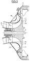
- FIG. 3 differs from the embodiment of FIG. 2 only in that the outer wall 12 has a convex localized zone 18 whose convexity is directed towards the interior of the cavity 11. is preferably obtained by simple local stamping of the sheet constituting the outer wall 12. This stamped area 18 thus causes an additional break of symmetry, in addition to that which already exists when a pipe 4, as shown in Figure 2 is located at another location in the cavity 11.
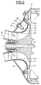
- the embodiment illustrated in FIG. 4 differs from the embodiment of FIG. 3 in that a radially disposed portion of sheet 19 is welded to the inner face of the outer wall 12 of the cavity 11. welded sheet 19 thus protrudes inside the cavity 11 and prevents the birth of rotating acoustic waves in the cavity 11.
- the tubing 4 may also be provided at another location on the cavity 11.
- the dimensions of the welded sheet metal portion 19, of square shape in the embodiment illustrated by way of example in FIG. 4 are such that said portion of welded sheet 19 extends from the outer wall 12 in the direction of the inner wall 10 without however going to come into contact with the latter.
- the welded sheet metal portion 19 could also be fixed on the inner wall 10 while extending in the opposite direction towards the outer wall 12.
- FIG. 5 differs from the embodiment of FIG. 4 in that a screw 20 passes through the outer wall 12 of the cavity 11 projecting inside said cavity 11 over a certain length.
- the outer wall 12 has a zone 13 provided with a tapping which can cooperate with the thread of the screw 20 whose head 21 remains outside the outer wall 12.
- the dimensions of the screw 20 projecting inside the cavity 11 are such that said screw extends towards the inner wall 10 in a radial plane without however coming into contact with the inner wall 10.
- a symmetry breaking means has been introduced inside the symmetrical cavity that can prevent the birth of rotating acoustic waves and therefore to avoid the resonance of the cavity, regardless of the flow velocity in the turbomachine.
Landscapes
- Engineering & Computer Science (AREA)
- Mechanical Engineering (AREA)
- General Engineering & Computer Science (AREA)
- Structures Of Non-Positive Displacement Pumps (AREA)
- Exhaust Silencers (AREA)
- Turbine Rotor Nozzle Sealing (AREA)
- Vibration Prevention Devices (AREA)
- Springs (AREA)
- Suspension Of Electric Lines Or Cables (AREA)
Applications Claiming Priority (2)
| Application Number | Priority Date | Filing Date | Title |
|---|---|---|---|
| FR0003490A FR2806442B1 (fr) | 2000-03-17 | 2000-03-17 | Turbomachine comportant un dispositif de suppression des vibrations dues aux resonances acoustiques |
| FR0003490 | 2000-03-17 |
Publications (2)
| Publication Number | Publication Date |
|---|---|
| EP1134361A1 EP1134361A1 (fr) | 2001-09-19 |
| EP1134361B1 true EP1134361B1 (fr) | 2006-05-31 |
Family
ID=8848249
Family Applications (1)
| Application Number | Title | Priority Date | Filing Date |
|---|---|---|---|
| EP01400573A Expired - Lifetime EP1134361B1 (fr) | 2000-03-17 | 2001-03-06 | Turbomachine comportant un dispositif de suppression des vibrations |
Country Status (11)
| Country | Link |
|---|---|
| US (1) | US6450761B2 (https=) |
| EP (1) | EP1134361B1 (https=) |
| JP (1) | JP4719368B2 (https=) |
| AT (1) | ATE328192T1 (https=) |
| CA (1) | CA2341839C (https=) |
| CY (1) | CY1105534T1 (https=) |
| DE (1) | DE60120017T2 (https=) |
| DK (1) | DK1134361T3 (https=) |
| ES (1) | ES2261357T3 (https=) |
| FR (1) | FR2806442B1 (https=) |
| PT (1) | PT1134361E (https=) |
Families Citing this family (1)
| Publication number | Priority date | Publication date | Assignee | Title |
|---|---|---|---|---|
| WO2006090152A1 (en) * | 2005-02-23 | 2006-08-31 | Cummins Turbo Technologies Limited | Compressor |
Family Cites Families (14)
| Publication number | Priority date | Publication date | Assignee | Title |
|---|---|---|---|---|
| GB1132485A (en) * | 1966-06-10 | 1968-11-06 | Alexandr Georgievich Ivchenko | A centrifugal compressor having a surge-elimination device |
| US4436481A (en) * | 1981-06-15 | 1984-03-13 | The Garrett Corporation | Intake vortex whistle silencing apparatus and methods |
| JPS5968199U (ja) * | 1982-10-29 | 1984-05-09 | 石川島播磨重工業株式会社 | 遠心式圧縮機の消音装置 |
| US4844695A (en) * | 1988-07-05 | 1989-07-04 | Pratt & Whitney Canada Inc. | Variable flow radial compressor inlet flow fences |
| US4981018A (en) * | 1989-05-18 | 1991-01-01 | Sundstrand Corporation | Compressor shroud air bleed passages |
| US5246335A (en) * | 1991-05-01 | 1993-09-21 | Ishikawajima-Harimas Jukogyo Kabushiki Kaisha | Compressor casing for turbocharger and assembly thereof |
| US5186601A (en) * | 1991-09-16 | 1993-02-16 | Sundstrand Corp. | Compressor shroud air bleed arrangement |
| US5236301A (en) * | 1991-12-23 | 1993-08-17 | Allied-Signal Inc. | Centrifugal compressor |
| US5314300A (en) * | 1992-01-13 | 1994-05-24 | Fasco Industries, Inc. | Noise control device for centrifugal blower |
| DE4219249C2 (de) * | 1992-06-12 | 1994-03-31 | Kuehnle Kopp Kausch Ag | Radialverdichter, insbesondere eines Turboladers |
| DE59206751D1 (de) * | 1992-10-17 | 1996-08-14 | Asea Brown Boveri | Stabilisierungseinrichtung zur Kennfelderweiterung eines Verdichters |
| US5295785A (en) * | 1992-12-23 | 1994-03-22 | Caterpillar Inc. | Turbocharger having reduced noise emissions |
| DE19727139C2 (de) * | 1997-06-26 | 2000-04-20 | Daimler Chrysler Ag | Verdichter eines Abgasturboladers |
| US6183195B1 (en) * | 1999-02-04 | 2001-02-06 | Pratt & Whitney Canada Corp. | Single slot impeller bleed |
-
2000
- 2000-03-17 FR FR0003490A patent/FR2806442B1/fr not_active Expired - Fee Related
-
2001
- 2001-03-06 AT AT01400573T patent/ATE328192T1/de not_active IP Right Cessation
- 2001-03-06 DE DE60120017T patent/DE60120017T2/de not_active Expired - Lifetime
- 2001-03-06 EP EP01400573A patent/EP1134361B1/fr not_active Expired - Lifetime
- 2001-03-06 DK DK01400573T patent/DK1134361T3/da active
- 2001-03-06 ES ES01400573T patent/ES2261357T3/es not_active Expired - Lifetime
- 2001-03-06 PT PT01400573T patent/PT1134361E/pt unknown
- 2001-03-15 US US09/808,189 patent/US6450761B2/en not_active Expired - Lifetime
- 2001-03-16 JP JP2001075980A patent/JP4719368B2/ja not_active Expired - Lifetime
- 2001-03-16 CA CA002341839A patent/CA2341839C/fr not_active Expired - Fee Related
-
2006
- 2006-08-30 CY CY20061101225T patent/CY1105534T1/el unknown
Also Published As
| Publication number | Publication date |
|---|---|
| DE60120017D1 (de) | 2006-07-06 |
| JP2001317497A (ja) | 2001-11-16 |
| US20010036402A1 (en) | 2001-11-01 |
| US6450761B2 (en) | 2002-09-17 |
| CA2341839C (fr) | 2008-09-23 |
| DK1134361T3 (da) | 2006-10-02 |
| ATE328192T1 (de) | 2006-06-15 |
| JP4719368B2 (ja) | 2011-07-06 |
| EP1134361A1 (fr) | 2001-09-19 |
| PT1134361E (pt) | 2006-09-29 |
| DE60120017T2 (de) | 2006-10-05 |
| FR2806442A1 (fr) | 2001-09-21 |
| FR2806442B1 (fr) | 2003-01-10 |
| ES2261357T3 (es) | 2006-11-16 |
| CY1105534T1 (el) | 2010-07-28 |
| CA2341839A1 (fr) | 2001-09-17 |
Similar Documents
| Publication | Publication Date | Title |
|---|---|---|
| EP2028375B1 (fr) | Soufflante pour turbomachine d'aéronef comprenant une bride d'équilibrage masquée par le cône d'entrée | |
| EP1455055B1 (fr) | Turbomachine disposant de secteurs d'anneau refroidis | |
| EP1881179B1 (fr) | Système de ventilation de paroi de chambre de combustion dans une turbomachine | |
| EP2318666B1 (fr) | Aubage fixe de turbomachine a masse reduite et turbomachine comportant au moins un tel aubage fixe | |
| CA2651055C (fr) | Compresseur de turboreacteur | |
| EP1406019B1 (fr) | Rotor à tambour pour une turbomachine | |
| CA2885650C (fr) | Carter et roue a aubes de turbomachine | |
| CA2746249A1 (fr) | Soufflante pour turbomachine comprenant un systeme d'equilibrage a trous borgnes de logement de masses, et turbomachine associee | |
| FR2931904A1 (fr) | Degagement d'aube de rotor de compresseur | |
| FR2901574A1 (fr) | Dispositif de guidage d'un flux d'air a l'entree d'une chambre de combustion dans une turbomachine | |
| WO2012114032A1 (fr) | Rotor de soufflante et turboréacteur associé | |
| EP1770244A1 (fr) | Aube de compresseur à sommet chanfreiné | |
| EP1469165B1 (fr) | Réduction de jeux dans une turbine à gaz | |
| EP2564031A1 (fr) | Piece anti-usure pour echasse d'aube de soufflante de turboreacteur | |
| FR2960603A1 (fr) | Diffuseur radial de turbomachine | |
| EP1134361B1 (fr) | Turbomachine comportant un dispositif de suppression des vibrations | |
| FR2794817A1 (fr) | Compresseur radial avec fenetes en paroi | |
| FR3087855A1 (fr) | Un turbocompresseur centrifuge ayant un trajet de flux de gaz comportant une chambre de detente | |
| FR2644524A1 (fr) | Aubes a pied marteau a positionnement angulaire ameliore | |
| FR2877059A1 (fr) | Biellette de commande destinee a l'entrainement d'une aube a calage variable | |
| FR2736103A1 (fr) | Pompe turbomoleculaire | |
| CA2726905C (fr) | Couvercle de compresseur de turbomoteur a butee axiale | |
| FR3042825B1 (fr) | Aube et disque de soufflante | |
| FR3137715A1 (fr) | Système de verrouillage d'une aube d'un module de soufflante par levier de serrage | |
| FR3086982A1 (fr) | Roue monobloc pour un turbocompresseur |
Legal Events
| Date | Code | Title | Description |
|---|---|---|---|
| PUAI | Public reference made under article 153(3) epc to a published international application that has entered the european phase |
Free format text: ORIGINAL CODE: 0009012 |
|
| AK | Designated contracting states |
Kind code of ref document: A1 Designated state(s): AT BE CH CY DE DK ES FI FR GB GR IE IT LI LU MC NL PT SE TR |
|
| AX | Request for extension of the european patent |
Free format text: AL;LT;LV;MK;RO;SI |
|
| 17P | Request for examination filed |
Effective date: 20020226 |
|
| AKX | Designation fees paid |
Free format text: AT BE CH CY DE DK ES FI FR GB GR IE IT LI LU MC NL PT SE TR |
|
| 17Q | First examination report despatched |
Effective date: 20041123 |
|
| GRAP | Despatch of communication of intention to grant a patent |
Free format text: ORIGINAL CODE: EPIDOSNIGR1 |
|
| GRAS | Grant fee paid |
Free format text: ORIGINAL CODE: EPIDOSNIGR3 |
|
| GRAA | (expected) grant |
Free format text: ORIGINAL CODE: 0009210 |
|
| AK | Designated contracting states |
Kind code of ref document: B1 Designated state(s): AT BE CH CY DE DK ES FI FR GB GR IE IT LI LU MC NL PT SE TR |
|
| PG25 | Lapsed in a contracting state [announced via postgrant information from national office to epo] |
Ref country code: IT Free format text: LAPSE BECAUSE OF FAILURE TO SUBMIT A TRANSLATION OF THE DESCRIPTION OR TO PAY THE FEE WITHIN THE PRESCRIBED TIME-LIMIT;WARNING: LAPSES OF ITALIAN PATENTS WITH EFFECTIVE DATE BEFORE 2007 MAY HAVE OCCURRED AT ANY TIME BEFORE 2007. THE CORRECT EFFECTIVE DATE MAY BE DIFFERENT FROM THE ONE RECORDED. Effective date: 20060531 |
|
| REG | Reference to a national code |
Ref country code: GB Ref legal event code: FG4D Free format text: NOT ENGLISH Ref country code: CH Ref legal event code: EP |
|
| GBT | Gb: translation of ep patent filed (gb section 77(6)(a)/1977) |
Effective date: 20060531 |
|
| REG | Reference to a national code |
Ref country code: SE Ref legal event code: TRGR |
|
| REG | Reference to a national code |
Ref country code: IE Ref legal event code: FG4D Free format text: LANGUAGE OF EP DOCUMENT: FRENCH |
|
| REF | Corresponds to: |
Ref document number: 60120017 Country of ref document: DE Date of ref document: 20060706 Kind code of ref document: P |
|
| REG | Reference to a national code |
Ref country code: GR Ref legal event code: EP Ref document number: 20060401950 Country of ref document: GR |
|
| REG | Reference to a national code |
Ref country code: PT Ref legal event code: SC4A Effective date: 20060717 |
|
| REG | Reference to a national code |
Ref country code: DK Ref legal event code: T3 |
|
| REG | Reference to a national code |
Ref country code: ES Ref legal event code: FG2A Ref document number: 2261357 Country of ref document: ES Kind code of ref document: T3 |
|
| PLBE | No opposition filed within time limit |
Free format text: ORIGINAL CODE: 0009261 |
|
| STAA | Information on the status of an ep patent application or granted ep patent |
Free format text: STATUS: NO OPPOSITION FILED WITHIN TIME LIMIT |
|
| 26N | No opposition filed |
Effective date: 20070301 |
|
| PGFP | Annual fee paid to national office [announced via postgrant information from national office to epo] |
Ref country code: IE Payment date: 20100225 Year of fee payment: 10 Ref country code: LU Payment date: 20100224 Year of fee payment: 10 Ref country code: CH Payment date: 20100219 Year of fee payment: 10 Ref country code: PT Payment date: 20100224 Year of fee payment: 10 Ref country code: MC Payment date: 20100219 Year of fee payment: 10 Ref country code: ES Payment date: 20100309 Year of fee payment: 10 Ref country code: DK Payment date: 20100224 Year of fee payment: 10 |
|
| PGFP | Annual fee paid to national office [announced via postgrant information from national office to epo] |
Ref country code: FI Payment date: 20100222 Year of fee payment: 10 |
|
| PGFP | Annual fee paid to national office [announced via postgrant information from national office to epo] |
Ref country code: TR Payment date: 20100303 Year of fee payment: 10 Ref country code: BE Payment date: 20100223 Year of fee payment: 10 Ref country code: AT Payment date: 20100219 Year of fee payment: 10 |
|
| PGFP | Annual fee paid to national office [announced via postgrant information from national office to epo] |
Ref country code: NL Payment date: 20100224 Year of fee payment: 10 |
|
| PGFP | Annual fee paid to national office [announced via postgrant information from national office to epo] |
Ref country code: SE Payment date: 20100224 Year of fee payment: 10 Ref country code: CY Payment date: 20100222 Year of fee payment: 10 |
|
| PGFP | Annual fee paid to national office [announced via postgrant information from national office to epo] |
Ref country code: GR Payment date: 20100222 Year of fee payment: 10 |
|
| REG | Reference to a national code |
Ref country code: PT Ref legal event code: MM4A Free format text: LAPSE DUE TO NON-PAYMENT OF FEES Effective date: 20110906 |
|
| BERE | Be: lapsed |
Owner name: TURBOMECA Effective date: 20110331 |
|
| REG | Reference to a national code |
Ref country code: NL Ref legal event code: V1 Effective date: 20111001 |
|
| PG25 | Lapsed in a contracting state [announced via postgrant information from national office to epo] |
Ref country code: MC Free format text: LAPSE BECAUSE OF NON-PAYMENT OF DUE FEES Effective date: 20110331 Ref country code: PT Free format text: LAPSE BECAUSE OF NON-PAYMENT OF DUE FEES Effective date: 20110906 |
|
| REG | Reference to a national code |
Ref country code: CH Ref legal event code: PL Ref country code: DK Ref legal event code: EBP |
|
| REG | Reference to a national code |
Ref country code: SE Ref legal event code: EUG |
|
| PG25 | Lapsed in a contracting state [announced via postgrant information from national office to epo] |
Ref country code: CY Free format text: LAPSE BECAUSE OF NON-PAYMENT OF DUE FEES Effective date: 20110306 Ref country code: AT Free format text: LAPSE BECAUSE OF NON-PAYMENT OF DUE FEES Effective date: 20110306 Ref country code: FI Free format text: LAPSE BECAUSE OF NON-PAYMENT OF DUE FEES Effective date: 20110306 |
|
| PG25 | Lapsed in a contracting state [announced via postgrant information from national office to epo] |
Ref country code: BE Free format text: LAPSE BECAUSE OF NON-PAYMENT OF DUE FEES Effective date: 20110331 |
|
| REG | Reference to a national code |
Ref country code: IE Ref legal event code: MM4A |
|
| PG25 | Lapsed in a contracting state [announced via postgrant information from national office to epo] |
Ref country code: IE Free format text: LAPSE BECAUSE OF NON-PAYMENT OF DUE FEES Effective date: 20110307 Ref country code: LI Free format text: LAPSE BECAUSE OF NON-PAYMENT OF DUE FEES Effective date: 20110331 Ref country code: NL Free format text: LAPSE BECAUSE OF NON-PAYMENT OF DUE FEES Effective date: 20111001 Ref country code: CH Free format text: LAPSE BECAUSE OF NON-PAYMENT OF DUE FEES Effective date: 20110331 |
|
| PG25 | Lapsed in a contracting state [announced via postgrant information from national office to epo] |
Ref country code: GR Free format text: LAPSE BECAUSE OF NON-PAYMENT OF DUE FEES Effective date: 20111004 |
|
| REG | Reference to a national code |
Ref country code: ES Ref legal event code: FD2A Effective date: 20120424 |
|
| PG25 | Lapsed in a contracting state [announced via postgrant information from national office to epo] |
Ref country code: DK Free format text: LAPSE BECAUSE OF NON-PAYMENT OF DUE FEES Effective date: 20110331 |
|
| PG25 | Lapsed in a contracting state [announced via postgrant information from national office to epo] |
Ref country code: ES Free format text: LAPSE BECAUSE OF NON-PAYMENT OF DUE FEES Effective date: 20110307 |
|
| PG25 | Lapsed in a contracting state [announced via postgrant information from national office to epo] |
Ref country code: SE Free format text: LAPSE BECAUSE OF NON-PAYMENT OF DUE FEES Effective date: 20110307 |
|
| PG25 | Lapsed in a contracting state [announced via postgrant information from national office to epo] |
Ref country code: LU Free format text: LAPSE BECAUSE OF NON-PAYMENT OF DUE FEES Effective date: 20110306 |
|
| PG25 | Lapsed in a contracting state [announced via postgrant information from national office to epo] |
Ref country code: TR Free format text: LAPSE BECAUSE OF NON-PAYMENT OF DUE FEES Effective date: 20110306 |
|
| REG | Reference to a national code |
Ref country code: FR Ref legal event code: PLFP Year of fee payment: 16 |
|
| REG | Reference to a national code |
Ref country code: FR Ref legal event code: PLFP Year of fee payment: 17 |
|
| REG | Reference to a national code |
Ref country code: FR Ref legal event code: CD Owner name: SAFRAN HELICOPTER ENGINES, FR Effective date: 20170727 |
|
| REG | Reference to a national code |
Ref country code: FR Ref legal event code: PLFP Year of fee payment: 18 |
|
| PGFP | Annual fee paid to national office [announced via postgrant information from national office to epo] |
Ref country code: DE Payment date: 20200218 Year of fee payment: 20 Ref country code: GB Payment date: 20200221 Year of fee payment: 20 Ref country code: IT Payment date: 20200218 Year of fee payment: 20 |
|
| PGFP | Annual fee paid to national office [announced via postgrant information from national office to epo] |
Ref country code: FR Payment date: 20200220 Year of fee payment: 20 |
|
| REG | Reference to a national code |
Ref country code: DE Ref legal event code: R071 Ref document number: 60120017 Country of ref document: DE |
|
| REG | Reference to a national code |
Ref country code: GB Ref legal event code: PE20 Expiry date: 20210305 |
|
| PG25 | Lapsed in a contracting state [announced via postgrant information from national office to epo] |
Ref country code: GB Free format text: LAPSE BECAUSE OF EXPIRATION OF PROTECTION Effective date: 20210305 |