EP1133597B1 - Method and device for measurement of the retention profile and for control of the retention in a paper/board machine - Google Patents
Method and device for measurement of the retention profile and for control of the retention in a paper/board machine Download PDFInfo
- Publication number
- EP1133597B1 EP1133597B1 EP99957351A EP99957351A EP1133597B1 EP 1133597 B1 EP1133597 B1 EP 1133597B1 EP 99957351 A EP99957351 A EP 99957351A EP 99957351 A EP99957351 A EP 99957351A EP 1133597 B1 EP1133597 B1 EP 1133597B1
- Authority
- EP
- European Patent Office
- Prior art keywords
- retention
- flow
- web
- measurement
- profile
- Prior art date
- Legal status (The legal status is an assumption and is not a legal conclusion. Google has not performed a legal analysis and makes no representation as to the accuracy of the status listed.)
- Expired - Lifetime
Links
- 230000014759 maintenance of location Effects 0.000 title claims abstract description 82
- 238000005259 measurement Methods 0.000 title claims abstract description 33
- 238000000034 method Methods 0.000 title claims description 13
- XLYOFNOQVPJJNP-UHFFFAOYSA-N water Substances O XLYOFNOQVPJJNP-UHFFFAOYSA-N 0.000 claims abstract description 36
- 239000003795 chemical substances by application Substances 0.000 claims abstract description 33
- 230000033228 biological regulation Effects 0.000 claims abstract description 25
- 230000001105 regulatory effect Effects 0.000 claims abstract description 15
- 239000007788 liquid Substances 0.000 claims abstract description 7
- 230000001276 controlling effect Effects 0.000 claims abstract 3
- 239000012895 dilution Substances 0.000 claims description 28
- 238000010790 dilution Methods 0.000 claims description 28
- 239000000945 filler Substances 0.000 claims description 12
- 238000010276 construction Methods 0.000 claims description 8
- 239000000463 material Substances 0.000 claims 1
- 238000004458 analytical method Methods 0.000 abstract 1
- 238000005070 sampling Methods 0.000 description 6
- 239000000835 fiber Substances 0.000 description 3
- 238000011109 contamination Methods 0.000 description 2
- 238000010586 diagram Methods 0.000 description 2
- 239000004744 fabric Substances 0.000 description 2
- 239000000706 filtrate Substances 0.000 description 2
- 239000007787 solid Substances 0.000 description 2
- 239000000243 solution Substances 0.000 description 2
- 239000000725 suspension Substances 0.000 description 2
- 238000010521 absorption reaction Methods 0.000 description 1
- 230000000903 blocking effect Effects 0.000 description 1
- 239000012765 fibrous filler Substances 0.000 description 1
- 239000002657 fibrous material Substances 0.000 description 1
- 230000007257 malfunction Effects 0.000 description 1
- 238000004519 manufacturing process Methods 0.000 description 1
- 230000028161 membrane depolarization Effects 0.000 description 1
- 230000003287 optical effect Effects 0.000 description 1
- 239000002245 particle Substances 0.000 description 1
- 239000000126 substance Substances 0.000 description 1
- 230000001360 synchronised effect Effects 0.000 description 1
Images


Classifications
-
- D—TEXTILES; PAPER
- D21—PAPER-MAKING; PRODUCTION OF CELLULOSE
- D21G—CALENDERS; ACCESSORIES FOR PAPER-MAKING MACHINES
- D21G9/00—Other accessories for paper-making machines
- D21G9/0009—Paper-making control systems
- D21G9/0027—Paper-making control systems controlling the forming section
-
- Y—GENERAL TAGGING OF NEW TECHNOLOGICAL DEVELOPMENTS; GENERAL TAGGING OF CROSS-SECTIONAL TECHNOLOGIES SPANNING OVER SEVERAL SECTIONS OF THE IPC; TECHNICAL SUBJECTS COVERED BY FORMER USPC CROSS-REFERENCE ART COLLECTIONS [XRACs] AND DIGESTS
- Y10—TECHNICAL SUBJECTS COVERED BY FORMER USPC
- Y10S—TECHNICAL SUBJECTS COVERED BY FORMER USPC CROSS-REFERENCE ART COLLECTIONS [XRACs] AND DIGESTS
- Y10S162/00—Paper making and fiber liberation
- Y10S162/09—Uses for paper making sludge
- Y10S162/10—Computer control of paper making variables
- Y10S162/11—Wet end paper making variables
Definitions
- the invention concerns a method and a device for measurement and regulation of the retention profile of the web in a paper/board machine.
- the invention is related to the dilution liquid system in a paper machine and more specifically to measurement and control of the retention profile of the web in the cross direction of the machine. Further, by means of the device in accordance with the invention, it is possible to locate various situations of malfunction in the wire part of a paper machine or equivalent.
- a dilution headbox is known from the applicant's Patent Applications FI-901593, FI-933027 and FI-942780 of earlier dates.
- a dilution headbox the basis weight of the web is regulated so that a dilution flow is passed through a valve to different areas of width of the headbox and so that the quantity of said flow is regulated.
- the dilution flow is mixed with the stock flow passed from the inlet header of the headbox.
- As the dilution liquid it is possible to use pure water or, for example, filtrate water returned from the web.
- FI 92, 229 a construction of a three-way dilution valve is described, which is used for regulation of the dilution flow.
- document WO-A-98 32916 discloses a control system for a paper machine, in which one or more properties of a paper web are measured and the measurement signal thus obtained is fed to the control system. The actuators of the headbox of the paper machine are controlled based on these measurements.
- a stock suspension jet is discharged out of the slice opening in paper or board machines onto a forming wire or into a gap between wires.
- the proportion of the solid matter that remains on the wire i.e. the retention, consists of a fibre retention, whose proportion is about 60...80 %, and of a filler retention, whose proportion is about 20...40 %.
- the filtrate passing through the wire i.e. the so-called white water, contains an abundance of fibrous material and fillers, and it is returned back to the process of manufacture.
- Factors that affect the retention include, among other things, headbox consistency, construction of the wire part, and properties of the stock, such as distribution of fibre length, fillers, and added chemicals. Measurement of basis weight does not give a correct picture of the retention profile, for with a uniform basis weight profile, the fibre retention profile and the filler retention profile can, nevertheless, be uneven. This is why determination of the retention profile in the wire part would give a correct idea of the retention profiles.
- a retention agent For regulation of the retention, a retention agent is employed, whose function is to bind fillers and fines to the fibres in order that said agents should not depart from the web through the holes provided in the wire.
- the particle size of fillers and fines is considerably smaller than the size of the holes provided in the wire.
- the object of the invention is to provide a method of measurement for measurement of the retention profile.
- An object of the invention is to provide a method of regulation for regulation of the retention profile in the cross direction.
- a further object of the invention is to provide a device for measurement of the retention profile.
- An object of the invention is to provide a device for regulation of the retention profile.
- the device in accordance with the invention is characterized by the features defined in the characterizing part of claim 6.
- an arrangement is suggested for measurement and regulation of the retention profile in the cross direction of the machine.
- a white water sample is collected into a sampling vessel and transferred to an analyzer.
- the analyzer can also be integrated in a measurement head. After taking of the sample and after its transfer to the analyzer, the measurement head is transferred to the following measurement point. With this procedure, the retention profile can be determined across the width of the whole machine direction. Samples can be taken, for example, at intervals of 10 cm in the machine direction.
- the determined retention profile is utilized in the regulation of the dilution liquid system, in which connection each dilution liquid valve can be provided with the necessary regulation of the concentration of retention agent.
- a measurement arrangement accomplished in this way operates as on-line measurement, and it can be carried out constantly during the whole run.
- the measurement also provides information on problem situations, e.g. on blocking or contamination of the wire fabric, on incomplete mixing of retention agent, or on other situations of failure.
- Regulation of the retention profile is carried out so that the basis weight profile is not changed.
- a change in the basis weight of the paper arising from a change in the quantity of retention agent is compensated for by means of a change in the dilution quantity. For example, if a local addition of retention agent increases the basis weight, the dilution quantity at said point is increased.
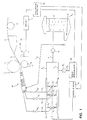
- Fig. 1 is an illustration in the form of a block diagram of the parts of a paper machine and of a system of measurement included in the system of regulation and control of the retention profile in an embodiment in accordance with the present invention.
- the stock suspension jet is discharged out of the slice opening of the headbox 10 into the forming gap between the forming rolls 11 and 12 and from the gap further onto the forming wire H.
- Fig. 1 also shows a suction box 13 and a guide roll 14.
- a sample collecting equipment 20 is placed, by whose means samples are taken out of the white water departing from the wire H.
- the white water is recovered into the wire pit 17, from which it is passed back into the papermaking process, mainly to be used as dilution water for the headbox.
- the high-consistency stock is fed into the wire pit 17 as a flow F m , and from the wire pit 17 the high-consistency stock is passed to the headbox 10 as a flow F in .
- a flow F 1 is passed through a pump P 1 , which flow is divided into flows F 2 and F 3 .
- the white-water flow F 2 is passed into a dilution header 24.
- a retention agent feed unit 18 supplies a retention agent flow F 4 through a pump P 2 to be added to the flow F 3 , which is passed further into a retention agent header 25.
- valves V 1 ...V n are three-way valves, by whose means the retention profile and the dilution profile are regulated. The regulation of said profiles is carried out independently from one another. For example, if a recess is noticed in the retention profile, retention agent is added to that location. Owing to the improved retention, more fibres, fines and fillers remain on the wire, in which connection the basis weight is increased in this area. In such a case, dilution water is added to said area in order that the basis weight profile should remain uniform.
- the control for the valves V 1 ...V n is obtained from the valve control unit 19.
- valves V 1 ... V n From the valves V 1 ... V n the stock flow is passed through the respective lines A 1 ...A n to the different positions of width in the headbox across the whole width of the headbox.
- the lines A 1 ...A n include ordinary throttle valves V 1 '...V n ' for regulation of the flow quantities.
- the valves V 1 ...V n are favourably valves to which it is possible to pass the flow portion Q 1 comprising the retention agent from the retention agent header 25 and the flow portion Q 2 comprising the dilution water alone from the dilution water header 24.
- the combined flow Q 1 + Q 2 is passed further into the lines A 1 ...A n and further, through the valve V 1 '...V n ' placed in each line, to the different positions of width in the headbox.
- the valves V 1 ...V n By means of the valves V 1 ...V n , the mixing ratio of the dilution flow passed from the dilution water header 24 to the flow containing retention agent and passed from the retention agent header 25, i.e. the retention ratio, is regulated.
- the flow Q 1 is increased, the flow Q 2 is reduced by a corresponding amount, and the other way round.
- the sum flow Q 1 + Q 2 remains invariable, and said combined flow is passed through the ordinary throttle valves V 1 '...V n ' to the different positions of width in the headbox.
- valves V 1 '...V n ' By means of regulation of the valves V 1 '...V n ', it is possible to regulate the flow quantity of the sum flow Q 1 + Q 2 and, thereby, the basis weight of the web at different positions of width with the retention ratio regulated by means of each particular valve V 1 ...V n .
- a joint operation of the valves V 1 and V 1 ' can also be accomplished, for example, by means of one valve, which is described in the FI Patent No. 92, 229.
- the device 20 for taking samples from the white water is favourably traversing, and by its means samples are taken from the white water preferably with uniform spacing across the entire width of the wire H.
- the sample collected from each cross-direction location is carried through a transfer pipe 23 to the white water analyzer 15, which determines the concentrations of solid matter and fillers present in the sample.
- the device for 20 taking samples can also be stationary (e.g. a pipe) so that it comprises sampling compartments opened one at a time for taking samples in the cross direction.
- a white water analyzer 15 it is possible to use, for example, a "Kajaani RM-200" analyzer, whose operation is based on optical on-line measurement from a constant flow of samples.
- the detector of the analyzer measures the depolarization, attenuation and backscattering and absorption at different wave lengths from laser light passing through the sample.
- some other analyzer for determination of the properties of the white water.
- the white water analyzer 15 transmits the data analyzed from the sample to the paper machine control unit 16, which uses the analyzed data for the control of the paper machine.
- the paper machine control unit 16 controls the retention agent feed unit 18 and the valve control unit 19.
- Fig. 2 illustrates the location of the traversing sampling unit 20 in the vicinity of the forming wire H and of the forming rolls 11 and 12.
- the stock M is fed in the direction indicated by the arrow between the forming rolls 11 and 12 and a ribbed shoe L.
- the carrier 21 of the traversing sampling head remains stationary at each sampling point for the time of collecting of the sample. Typically, the taking of a sample takes about 30 seconds, and samples are taken at intervals of 10 cm.
- the movement of the carrier 21 of the traversing sampling head is preferably synchronized, so that the sample is always taken from the same position of width in each series of measurement of the retention profile.
- Fig. 3 illustrates the area of the rectangle drawn with a dashed line in Fig. 2, which figure shows a detail of the sample collecting trough 22.
- the collecting trough 22 is placed at a point which represents about 40 per cent of the water that is drained.
- the water sample passes from the collecting trough into a transfer pipe 23, along which it is passed to the analyzer 15.
- the system of measurement of the retention profile is connected to each particular valve V 1 ...V n that regulates the mixing ratio (mixing ratio of retention agent) as a feedback connection so that from each point of width the measurement data are passed to the valve V 1 ...V n that regulates the retention profile at said point of width.
- the valves V 1 ...V n in the discharge line A 1 ...A n departing from the valves, there can be a separate throttle valve V 1 '...V n ' which regulates the flow quantity and by whose means the basis weight of the web can be regulated additionally across the web width.
- valves V 1 , V 1 ', V 2 , V 2 ' can also be accomplished by means of a single-valve solution in accordance with the FI Patent No. 92,229.
- the regulation in accordance with the present invention it is possible to provide a retention profile as straight as possible across the web width.
- the device is also suitable for clearing up situations of problems, for example, in a situation in which the retention agent has been mixed incompletely or in which there are blocked portions or contaminations in the wire fabric.
- Fig. 4 illustrates an exemplifying embodiment of a solution of a three-way valve as described in the FI Patent 92,229 , which valve is suited for regulation of the retention agent in the present invention.
- the retention agent is passed, for example, into the liquid flow Q 1
- the flow Q 2 which may consist of pure water, is passed into the valve V while the covering part 101 pivoting on the spindle 100 regulates the coverages of the inlet openings E 1 and E 2 .
- the other opening E 2 is being closed, or the other way round. In this way the flow quantity remains invariable, but the mixing ratio of the retention agent in the combined flow Q 1 + Q 2 is regulated.
- valve V shown in the figure can be such that the covering part 101 and the spindle 100 can be shifted axially in the direction X, in which case, with a certain mixing ratio, it is also possible to regulate the flow quantity.
- Said property can be substituted for by means of the construction described above, in which separate throttle valves are employed after the three-way valve V 1 ...V n .
Landscapes
- Paper (AREA)
- Sampling And Sample Adjustment (AREA)
Applications Claiming Priority (3)
| Application Number | Priority Date | Filing Date | Title |
|---|---|---|---|
| FI982560A FI112961B (fi) | 1998-11-26 | 1998-11-26 | Menetelmä ja laite paperikoneen/kartonkikoneen retentioprofiilin mittaamiseksi ja retention hallitsemiseksi |
| FI982560 | 1998-11-26 | ||
| PCT/FI1999/000975 WO2000031338A1 (en) | 1998-11-26 | 1999-11-25 | Method and device for measurement of the retention profile and for control of the retention in a paper/board machine |
Publications (2)
| Publication Number | Publication Date |
|---|---|
| EP1133597A1 EP1133597A1 (en) | 2001-09-19 |
| EP1133597B1 true EP1133597B1 (en) | 2005-01-05 |
Family
ID=8552989
Family Applications (1)
| Application Number | Title | Priority Date | Filing Date |
|---|---|---|---|
| EP99957351A Expired - Lifetime EP1133597B1 (en) | 1998-11-26 | 1999-11-25 | Method and device for measurement of the retention profile and for control of the retention in a paper/board machine |
Country Status (9)
| Country | Link |
|---|---|
| US (1) | US6471827B2 (enExample) |
| EP (1) | EP1133597B1 (enExample) |
| JP (1) | JP2002530548A (enExample) |
| AT (1) | ATE286553T1 (enExample) |
| AU (1) | AU1508000A (enExample) |
| CA (1) | CA2352319C (enExample) |
| DE (1) | DE69923082T2 (enExample) |
| FI (1) | FI112961B (enExample) |
| WO (1) | WO2000031338A1 (enExample) |
Families Citing this family (4)
| Publication number | Priority date | Publication date | Assignee | Title |
|---|---|---|---|---|
| FI116241B (fi) * | 2002-05-06 | 2005-10-14 | Metso Automation Oy | Menetelmä ja laitteisto paperikoneen viiraosan retention määrittämiseksi |
| DE102005051656A1 (de) * | 2005-10-28 | 2007-05-03 | Voith Patent Gmbh | Verfahren und Vorrichtung zur Herstellung einer Faserstoffbahn |
| US8715466B1 (en) * | 2012-10-19 | 2014-05-06 | Theodore Caouette | Method and system for reducing water loss in a paper mill |
| FI127377B (fi) * | 2015-10-30 | 2018-04-30 | Valmet Technologies Oy | Kuiturainakoneen syöttöjärjestelmä |
Family Cites Families (10)
| Publication number | Priority date | Publication date | Assignee | Title |
|---|---|---|---|---|
| US5022966A (en) * | 1989-01-27 | 1991-06-11 | Measurex Corporation | Process for controlling properties of travelling sheets |
| FI901593A7 (fi) | 1990-03-30 | 1991-10-01 | Valmet Paper Machinery Inc | Menetelmä paperi- tai kartonkikoneessa perälaatikosta tulevan massan säätämiseksi sekä paperi- tai kartonkikoneen perälaatikko |
| DE4237309A1 (enExample) | 1992-11-05 | 1993-04-08 | Voith Gmbh J M | |
| FI103995B (fi) * | 1993-06-17 | 1999-10-29 | Valmet Paper Machinery Inc | Menetelmä ja laite sekä säätöjärjestely paperikoneessa paperirainan poikittaisen profiilin hallinnassa |
| FI92229C (fi) | 1993-07-01 | 1994-10-10 | Valmet Paper Machinery Inc | Menetelmä ja laite perälaatikon säädössä |
| ATE212393T1 (de) | 1993-07-01 | 2002-02-15 | Metso Paper Inc | Verfahren und vorrichtung zur regelung eines stoffauflaufkasten |
| US6113741A (en) * | 1996-12-06 | 2000-09-05 | Eka Chemicals Ab | Process for the production of paper |
| US5779859A (en) * | 1996-12-13 | 1998-07-14 | J.M. Huber Corporation | Method of improving filler retention in papermaking |
| FI100345B (fi) * | 1997-01-24 | 1997-11-14 | Valmet Corp | Menetelmä ja laite paperikoneen perälaatikon säädössä |
| US6086716A (en) * | 1998-05-11 | 2000-07-11 | Honeywell-Measurex Corporation | Wet end control for papermaking machine |
-
1998
- 1998-11-26 FI FI982560A patent/FI112961B/fi active
-
1999
- 1999-11-25 DE DE69923082T patent/DE69923082T2/de not_active Expired - Lifetime
- 1999-11-25 WO PCT/FI1999/000975 patent/WO2000031338A1/en not_active Ceased
- 1999-11-25 CA CA002352319A patent/CA2352319C/en not_active Expired - Fee Related
- 1999-11-25 JP JP2000584138A patent/JP2002530548A/ja active Pending
- 1999-11-25 EP EP99957351A patent/EP1133597B1/en not_active Expired - Lifetime
- 1999-11-25 AU AU15080/00A patent/AU1508000A/en not_active Abandoned
- 1999-11-25 AT AT99957351T patent/ATE286553T1/de not_active IP Right Cessation
-
2001
- 2001-05-24 US US09/865,102 patent/US6471827B2/en not_active Expired - Fee Related
Also Published As
| Publication number | Publication date |
|---|---|
| EP1133597A1 (en) | 2001-09-19 |
| JP2002530548A (ja) | 2002-09-17 |
| FI982560A0 (fi) | 1998-11-26 |
| DE69923082D1 (de) | 2005-02-10 |
| FI982560A7 (fi) | 2000-05-27 |
| CA2352319A1 (en) | 2000-06-02 |
| AU1508000A (en) | 2000-06-13 |
| US20020060016A1 (en) | 2002-05-23 |
| US6471827B2 (en) | 2002-10-29 |
| CA2352319C (en) | 2008-01-08 |
| DE69923082T2 (de) | 2005-12-08 |
| ATE286553T1 (de) | 2005-01-15 |
| WO2000031338A1 (en) | 2000-06-02 |
| FI112961B (fi) | 2004-02-13 |
Similar Documents
| Publication | Publication Date | Title |
|---|---|---|
| US6491792B2 (en) | Apparatus for controlling a headbox in a paper machine | |
| EP0970277B1 (en) | Method and apparatus for control of a headbox in a paper machine | |
| EP1516954B1 (de) | Vorrichtung zur Beurteilung der Beschaffenheit mindestens eines umlaufenden Bandes | |
| CA2282751A1 (en) | Regulation system in a paper machine for controlling variation of the basis weight of the paper in the machine direction | |
| US6322666B1 (en) | Regulation system and method in a paper machine | |
| EP1133597B1 (en) | Method and device for measurement of the retention profile and for control of the retention in a paper/board machine | |
| CA2177920C (en) | Method and apparatus for lateral alignment of the cross-direction quality profile of a web in a paper machine | |
| DE19901211A1 (de) | Schnelle Regelung bzw. Steuerung einer Flächenmasse für Papiermaschinen | |
| US6562196B1 (en) | Method for optimizing the degree of flocculation | |
| CA2334706C (en) | Method for regulation of the surface level and the consistency in a tank for metering of a component stock | |
| US6993408B2 (en) | Method for the control of quality in a paper web | |
| JP2004515661A (ja) | 一定の充填剤含量を有する紙の製造方法 | |
| US6299731B1 (en) | Process and headbox system for improving consistency cross-direction profile of fiber web | |
| US20030136535A1 (en) | Process and apparatus for monitoring dewatering in a wet section of a paper machine | |
| US7763148B2 (en) | Method and apparatus for producing a fibrous web | |
| DE19716146A1 (de) | Verfahren zur Einstellung des Flächengewichtsquerprofils einer Papierbahn und Stoffauflauf einer Papiermaschine | |
| CA2277082A1 (en) | Method for controlling consistency of papermaking pulp |
Legal Events
| Date | Code | Title | Description |
|---|---|---|---|
| PUAI | Public reference made under article 153(3) epc to a published international application that has entered the european phase |
Free format text: ORIGINAL CODE: 0009012 |
|
| 17P | Request for examination filed |
Effective date: 20010510 |
|
| AK | Designated contracting states |
Kind code of ref document: A1 Designated state(s): AT BE CH CY DE DK ES FI FR GB GR IE IT LI LU MC NL PT SE |
|
| 17Q | First examination report despatched |
Effective date: 20030709 |
|
| GRAP | Despatch of communication of intention to grant a patent |
Free format text: ORIGINAL CODE: EPIDOSNIGR1 |
|
| GRAS | Grant fee paid |
Free format text: ORIGINAL CODE: EPIDOSNIGR3 |
|
| GRAA | (expected) grant |
Free format text: ORIGINAL CODE: 0009210 |
|
| AK | Designated contracting states |
Kind code of ref document: B1 Designated state(s): AT BE CH CY DE DK ES FI FR GB GR IE IT LI LU MC NL PT SE |
|
| PG25 | Lapsed in a contracting state [announced via postgrant information from national office to epo] |
Ref country code: NL Free format text: LAPSE BECAUSE OF FAILURE TO SUBMIT A TRANSLATION OF THE DESCRIPTION OR TO PAY THE FEE WITHIN THE PRESCRIBED TIME-LIMIT Effective date: 20050105 Ref country code: LI Free format text: LAPSE BECAUSE OF FAILURE TO SUBMIT A TRANSLATION OF THE DESCRIPTION OR TO PAY THE FEE WITHIN THE PRESCRIBED TIME-LIMIT Effective date: 20050105 Ref country code: IT Free format text: LAPSE BECAUSE OF FAILURE TO SUBMIT A TRANSLATION OF THE DESCRIPTION OR TO PAY THE FEE WITHIN THE PRESCRIBED TIME-LIMIT;WARNING: LAPSES OF ITALIAN PATENTS WITH EFFECTIVE DATE BEFORE 2007 MAY HAVE OCCURRED AT ANY TIME BEFORE 2007. THE CORRECT EFFECTIVE DATE MAY BE DIFFERENT FROM THE ONE RECORDED. Effective date: 20050105 Ref country code: FR Free format text: LAPSE BECAUSE OF NON-PAYMENT OF DUE FEES Effective date: 20050105 Ref country code: FI Free format text: LAPSE BECAUSE OF FAILURE TO SUBMIT A TRANSLATION OF THE DESCRIPTION OR TO PAY THE FEE WITHIN THE PRESCRIBED TIME-LIMIT Effective date: 20050105 Ref country code: ES Free format text: LAPSE BECAUSE OF FAILURE TO SUBMIT A TRANSLATION OF THE DESCRIPTION OR TO PAY THE FEE WITHIN THE PRESCRIBED TIME-LIMIT Effective date: 20050105 Ref country code: CH Free format text: LAPSE BECAUSE OF FAILURE TO SUBMIT A TRANSLATION OF THE DESCRIPTION OR TO PAY THE FEE WITHIN THE PRESCRIBED TIME-LIMIT Effective date: 20050105 Ref country code: BE Free format text: LAPSE BECAUSE OF FAILURE TO SUBMIT A TRANSLATION OF THE DESCRIPTION OR TO PAY THE FEE WITHIN THE PRESCRIBED TIME-LIMIT Effective date: 20050105 |
|
| REG | Reference to a national code |
Ref country code: GB Ref legal event code: FG4D |
|
| REG | Reference to a national code |
Ref country code: CH Ref legal event code: EP |
|
| REG | Reference to a national code |
Ref country code: IE Ref legal event code: FG4D |
|
| REF | Corresponds to: |
Ref document number: 69923082 Country of ref document: DE Date of ref document: 20050210 Kind code of ref document: P |
|
| PG25 | Lapsed in a contracting state [announced via postgrant information from national office to epo] |
Ref country code: SE Free format text: LAPSE BECAUSE OF FAILURE TO SUBMIT A TRANSLATION OF THE DESCRIPTION OR TO PAY THE FEE WITHIN THE PRESCRIBED TIME-LIMIT Effective date: 20050405 Ref country code: GR Free format text: LAPSE BECAUSE OF FAILURE TO SUBMIT A TRANSLATION OF THE DESCRIPTION OR TO PAY THE FEE WITHIN THE PRESCRIBED TIME-LIMIT Effective date: 20050405 Ref country code: DK Free format text: LAPSE BECAUSE OF FAILURE TO SUBMIT A TRANSLATION OF THE DESCRIPTION OR TO PAY THE FEE WITHIN THE PRESCRIBED TIME-LIMIT Effective date: 20050405 |
|
| NLV1 | Nl: lapsed or annulled due to failure to fulfill the requirements of art. 29p and 29m of the patents act | ||
| REG | Reference to a national code |
Ref country code: CH Ref legal event code: PL |
|
| PLBE | No opposition filed within time limit |
Free format text: ORIGINAL CODE: 0009261 |
|
| STAA | Information on the status of an ep patent application or granted ep patent |
Free format text: STATUS: NO OPPOSITION FILED WITHIN TIME LIMIT |
|
| PG25 | Lapsed in a contracting state [announced via postgrant information from national office to epo] |
Ref country code: IE Free format text: LAPSE BECAUSE OF NON-PAYMENT OF DUE FEES Effective date: 20051125 Ref country code: GB Free format text: LAPSE BECAUSE OF NON-PAYMENT OF DUE FEES Effective date: 20051125 Ref country code: CY Free format text: LAPSE BECAUSE OF FAILURE TO SUBMIT A TRANSLATION OF THE DESCRIPTION OR TO PAY THE FEE WITHIN THE PRESCRIBED TIME-LIMIT Effective date: 20051125 |
|
| PG25 | Lapsed in a contracting state [announced via postgrant information from national office to epo] |
Ref country code: MC Free format text: LAPSE BECAUSE OF NON-PAYMENT OF DUE FEES Effective date: 20051130 Ref country code: LU Free format text: LAPSE BECAUSE OF NON-PAYMENT OF DUE FEES Effective date: 20051130 |
|
| 26N | No opposition filed |
Effective date: 20051006 |
|
| REG | Reference to a national code |
Ref country code: GB Ref legal event code: FG4D |
|
| EN | Fr: translation not filed | ||
| GBPC | Gb: european patent ceased through non-payment of renewal fee |
Effective date: 20051125 |
|
| REG | Reference to a national code |
Ref country code: IE Ref legal event code: MM4A |
|
| PG25 | Lapsed in a contracting state [announced via postgrant information from national office to epo] |
Ref country code: PT Free format text: LAPSE BECAUSE OF NON-PAYMENT OF DUE FEES Effective date: 20050605 |
|
| PGFP | Annual fee paid to national office [announced via postgrant information from national office to epo] |
Ref country code: DE Payment date: 20091120 Year of fee payment: 11 Ref country code: AT Payment date: 20091113 Year of fee payment: 11 |
|
| REG | Reference to a national code |
Ref country code: DE Ref legal event code: R119 Ref document number: 69923082 Country of ref document: DE Effective date: 20110601 Ref country code: DE Ref legal event code: R119 Ref document number: 69923082 Country of ref document: DE Effective date: 20110531 |
|
| PG25 | Lapsed in a contracting state [announced via postgrant information from national office to epo] |
Ref country code: AT Free format text: LAPSE BECAUSE OF NON-PAYMENT OF DUE FEES Effective date: 20101125 |
|
| PG25 | Lapsed in a contracting state [announced via postgrant information from national office to epo] |
Ref country code: DE Free format text: LAPSE BECAUSE OF NON-PAYMENT OF DUE FEES Effective date: 20110531 |