EP1133335B1 - Sicherheitsvorrichtung zum Positionieren von Hanteln - Google Patents
Sicherheitsvorrichtung zum Positionieren von Hanteln Download PDFInfo
- Publication number
- EP1133335B1 EP1133335B1 EP99959098A EP99959098A EP1133335B1 EP 1133335 B1 EP1133335 B1 EP 1133335B1 EP 99959098 A EP99959098 A EP 99959098A EP 99959098 A EP99959098 A EP 99959098A EP 1133335 B1 EP1133335 B1 EP 1133335B1
- Authority
- EP
- European Patent Office
- Prior art keywords
- pawl
- ratchet
- spotting apparatus
- cable
- disengagement
- Prior art date
- Legal status (The legal status is an assumption and is not a legal conclusion. Google has not performed a legal analysis and makes no representation as to the accuracy of the status listed.)
- Expired - Lifetime
Links
- 230000004913 activation Effects 0.000 claims description 5
- 230000000712 assembly Effects 0.000 claims description 4
- 238000000429 assembly Methods 0.000 claims description 4
- 230000008878 coupling Effects 0.000 claims 1
- 238000010168 coupling process Methods 0.000 claims 1
- 238000005859 coupling reaction Methods 0.000 claims 1
- 238000007373 indentation Methods 0.000 description 9
- 210000003128 head Anatomy 0.000 description 7
- 238000009429 electrical wiring Methods 0.000 description 5
- 230000009467 reduction Effects 0.000 description 5
- 239000000725 suspension Substances 0.000 description 5
- 210000003205 muscle Anatomy 0.000 description 4
- 238000010276 construction Methods 0.000 description 3
- 239000003381 stabilizer Substances 0.000 description 3
- 230000013011 mating Effects 0.000 description 2
- 238000000034 method Methods 0.000 description 2
- 229910001369 Brass Inorganic materials 0.000 description 1
- 239000004677 Nylon Substances 0.000 description 1
- 230000003213 activating effect Effects 0.000 description 1
- 239000012190 activator Substances 0.000 description 1
- 239000010951 brass Substances 0.000 description 1
- 238000009413 insulation Methods 0.000 description 1
- 239000000463 material Substances 0.000 description 1
- 238000012986 modification Methods 0.000 description 1
- 230000004048 modification Effects 0.000 description 1
- 229920001778 nylon Polymers 0.000 description 1
- 230000003252 repetitive effect Effects 0.000 description 1
- 230000002441 reversible effect Effects 0.000 description 1
- 238000010008 shearing Methods 0.000 description 1
- 230000008719 thickening Effects 0.000 description 1
Images


Classifications
-
- A—HUMAN NECESSITIES
- A63—SPORTS; GAMES; AMUSEMENTS
- A63B—APPARATUS FOR PHYSICAL TRAINING, GYMNASTICS, SWIMMING, CLIMBING, OR FENCING; BALL GAMES; TRAINING EQUIPMENT
- A63B21/00—Exercising apparatus for developing or strengthening the muscles or joints of the body by working against a counterforce, with or without measuring devices
- A63B21/00181—Exercising apparatus for developing or strengthening the muscles or joints of the body by working against a counterforce, with or without measuring devices comprising additional means assisting the user to overcome part of the resisting force, i.e. assisted-active exercising
-
- A—HUMAN NECESSITIES
- A63—SPORTS; GAMES; AMUSEMENTS
- A63B—APPARATUS FOR PHYSICAL TRAINING, GYMNASTICS, SWIMMING, CLIMBING, OR FENCING; BALL GAMES; TRAINING EQUIPMENT
- A63B21/00—Exercising apparatus for developing or strengthening the muscles or joints of the body by working against a counterforce, with or without measuring devices
- A63B21/06—User-manipulated weights
- A63B21/078—Devices for bench press exercises, e.g. supports, guiding means
- A63B21/0783—Safety features for bar-bells, e.g. drop limiting means
Definitions
- the present invention relates generally to the field of exercise equipment. More particularly, the present invention relates to an apparatus which safely self-spots a weightlifter exercising with barbell or dumbbell assemblies.
- One common and effective program for lifters to increase overall muscle strength is to repetitively lift a predetermined weight for a predetermined number of sets. For maximum body muscle strength, the lifter attempts to exert all of his or her strength on the last one or two repetitions of each set.
- Another popular and effective program is for the lifter to repetitively lift a predetermined weight until the lifter's muscles reach a point of almost complete exhaustion.
- the lifter to safely utilize either program with free weights, it is both desirable and generally necessary for the lifter to engage the assistance of one or more spotters to observe the lifter during his or her exercise program.
- the spotters help lift and remove the weight when the lifter no longer has sufficient strength or energy to place the weight back to a stored position, typically on support arms of a weight support or a weight bench. Conducting these programs without a spotter is extremely dangerous to the lifter. Muscle exertion and exhaustion may cause the lifter to lose control of the weights, leading to the weights being uncontrollably dropped onto and injuring the lifter. Commonly, the lifter is unable to obtain a spotter before commencing the repetitive weight lifting programs of these types.
- the lifter is faced with the dilemma of either ignoring proper safety procedures and conducting the weight lifting exercises without the use of spotters or not conducting the weight lifting program altogether.
- This dilemma can occur whether the lifter utilizes dumbbells or weights removably mounted on a barbell.
- the weightlifting industry developed various devices that utilize motors to lift a weighted barbell for a lifter and eliminate the need for spotters.
- these devices have two movable cables traveling on respective, spaced-apart pulleys located at fixed positions on a frame. Distal ends of the cables are connected to the barbell, and proximal ends of the cables are operably connected to a single motor.
- the barbell is raised and lowered by respectively retracting and extending the cables by the motor.
- the motor must be activated for the cables to retract or extend, and the cables either extend or retract together, but not independently. Examples of such devices are described in U.S. Patent Numbers 4,949,959 and 5,048,826 .
- each cable retracts and extends from a drum which is operably mounted to a motor, as shown in U.S. Patent Number 4,998, 721 .
- each motor can actuate independently of the other, the motors are under constant low-level actuation to maintain tension on the cables, which requires the use of sensors.
- the cables respectively suspend from drums located at fixed positions with respect to the frame, the distance between the cables cannot be varied to accommodate different sized barbells or permit the use of dumbbells as "free-weights" with the cables traveling along a substantially vertical path.
- the lifter desires the device to lift the barbell, the lifter causes clutch to engage the shaft which permits the motor to controllably rotate the shaft and lift the barbell.
- the arm support assembly is not capable of providing "free-weight" full range of motion. Additionally, the chains can not move around their respective sprockets independently of the other.
- a free-weight assembly which provides independent travel of the cables to a certain amount is known from DE 39 36 377 A1 . That document discloses an exercising apparatus with a support column having holes arranged therein. Each end of a barbell is connected by a cable to a carriage which can slide up and down the support column. An engaging means provided on the carriage is biased by a spring to engage one of the holes arranged in the support column. An electromagnet normally forces the engaging means in a disengaged position. The electromagnet is operatively connected to a switch on the barbell. Upon actuation of the switch the electromagnet releases the engaging means to engage one of the next holes in the support column.
- the cables are slidably connected to the carriage by eyes provided on the carriage through which the cables extend. A thickening on each cable provides a stop for the relative movement of the cable with respect to the carriage.
- WO 96/09854 discloses a free-weight assembly with a barbell suspended by a pair of belts and a frame supporting a rotatable control shaft.
- the belts are wound around guide spools in the shaft.
- Adjacent each guide spool there is arranged a pawl and ratchet assembly comprising a ratchet wheel mounted fixedly to the control shaft and a pawl biased into engagement with the associated ratchet wheel to prevent the shaft from rotation.
- Each pawl is connected to an actuator mounted on each side of the barbell. Activating one activator causes the corresponding pawl to disengage from the associated ratchet wheel.
- This free-weight assembly does not allow for independent movement of the belts.
- the safety spotting apparatus of the invention comprises the features of claim 1.
- the preferred embodiment of the apparatus comprises a frame, two booms supported by the frame, two cables respectively movably extending from the booms, two reciprocating drives respectively operably connected to the cables to provide reciprocating movement of the cables, a rotary pawl clutch operably reciprocating movement of the cables and a motor assembly capable of retracting and extending the cables.
- the cables are connectable to the barbell or the dumbbells and provide reciprocating movement thereto in free-weight fashion.
- the booms are pivotally mounted to the frame so that the distance between the cables is variable.
- the reciprocating drive comprises an endless chain movably and operably extending about a rotatable sprocket gear and a rotatable drive shaft that is operably connected to the motor assembly, which is lockable to prevent rotation of the drive shaft.
- Counterweights are mounted to the chains to maintain tension on and assist in retracting the cables.
- the cables are respectively attached to the counterweights to prevent binding of the cables during reciprocating motion thereof or during pivotal movement of the booms.
- Independent reciprocating movement of each reciprocating drive is provided by operably connecting the respective chain to the drive shaft with the rotary pawl clutch.
- the rotary pawl clutch comprises a pawl base, at least one pawl pivotally mounted to the pawl base for each reciprocation drive, a solenoid mounted to the pawl base for each pawl to actuate the pawl, and a ratchet-sprocket gear engagable with the pawl.
- the pawl base is fixedly mounted to and rotates with the drive shaft.
- the ratchet-sprocket gear has a ratchet wheel portion and a sprocket portion.
- the ratchet-sprocket gear is rotatably mounted on the drive shaft with the ratchet wheel portion adjacent the pawl base.
- the ratchet wheel portion has a plurality of substantially evenly spaced indentations along the circumference thereof which are removably engagable with the pawl to prevent both rotation of the ratchet-sprocket gear and movement of the chain such that the respective cable is prohibited from extending from the boom.
- Dumbbells are suspendable from the respective cables by dumbbell clamps removably attached thereto.
- Each dumbbell clamp has a two spaced-apart plates mounted to one another and the plates are substantially identical in shape.
- the plates have a notch for receiving a grip of the dumbbell.
- An elongated slot intersects the notch, and a locking bar is slidably secured therein.
- a spring is disposed in each slot to bias the locking bar toward the notch to removably engage the grip, thereby securing the grip within the notch.
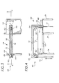
- Figure 1 of the drawings illustrates a barbell and dumbbell safety spotting apparatus 30 made in accordance with the present invention.
- the apparatus 30 is operative for assisting a weightlifter in the use of a weight assembly, such as a barbell assembly 22 or a pair of dumbbells 26, by supporting the weight of the weight assembly upon command of the weightlifter in the event the weightlifter is unable to lift or control the weight assembly.
- the barbell assembly 22 is of conventional construction and comprises a barbell 24 and a plurality of weights removably mounted thereon.
- the barbell 24 is further discussed below.
- the dumbbell 26 is of conventional construction and comprises a grip 28 and a pair of spaced apart weights which are either removably or fixedly mounted thereon.
- the preferred embodiment of the apparatus 30 comprises a frame 32, two booms 54, two cables 72, two reciprocating drives 96, a rotary pawl clutch 116 and a motor assembly 142.
- the cables 72 are connectable to the barbell 24 or the dumbbells 26 and retract and extend from the respective booms 54 to provide reciprocating vertical movement of the weight assembly in free-weight fashion. Normally, the cables 72 extend upwardly from the weight assembly to the respective booms 54.
- the frame 32 has two forward vertical support members 34 loftily supporting a boom support 36. Along a front face 38 of these vertical support members 34 are a plurality of apertures 40 which removably receive support pins 42.
- the support pins 42 are provided to receive the barbell 24 when the barbell 24 is not in use.
- the height of the pins 42 above ground or a supporting surface is variable and can be predetermined by the weightlifter by placing the pins 42 in the desire apertures 40.
- a plurality of boom stops 44 are disposed along the upper most portion of the boom support 36 at predetermined positions to prevent undesired pivoting of the booms 54.
- the boom stops 44 allow the weightlifter to adjust and maintain a desired distance between the cables 72 to accommodate various sized barbells 24 or to comfortably conduct a workout utilizing dumbbells 26.
- Rearwardly disposed in relation to the boom support 36 is the tower section 46 of the frame 32.
- the tower section 46 has a plurality of vertical support members 34 and side walls 48 mounted to the vertical support members 34. Sound insulation (not shown) is mounted to the side walls 48 within the tower section 46 to reduce noise during operation of the apparatus 30.
- a top wall 50 is mounted to and supported by the vertical support members 34 of the tower section 46.
- Stabilizer arms 53 extend between the upper and lower most portions of the forward vertical support members 34 and the tower section 46 to provide rigidity to the frame 32. With respect to the weight assembly, the stabilizer arms 53 are non-load bearing.
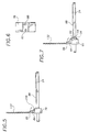
- the booms 54 comprise two spaced apart, elongated bars 56 and have a proximal end 58 and a distal end 60.
- Two spaced apart pulleys 62 are rotatably mounted on boom shafts 64 between the bars 56 respectively proximate the proximal and distal ends 58 and 60.
- a hollow pivot pin 66 is mounted to the bars 56 at the proximal end 58, and the pivot pin 66 is matingly and pivotally inserted within the receptacle 52 of the tower section 46.
- the pivot pin 66 has a shoulder 68, and nylon washers 70 are disposed on the pivot pin 66 between the shoulder 68 and the receptacle 52 to reduce friction therebetween as the boom 54 is pivoted.
- each cable 72 generally extends upwardly from the weight assembly to the distal end 60 of the boom 54.
- the cable 72 movably engages the two pulleys 62 and extends downwardly through the pivot pin 66 and the receptacle 52 into the tower section 46.
- the cable 72 is operably connected to one of the reciprocating drives 96 to provide reciprocating movement to the cable 12. The connection to the reciprocating drive 96 is discussed further below.
- the barbell 24 is releasably secured to the cables 72.
- a loop 74 is formed at the end of the cable 72 and secured with a cable stay 76, as generally shown in Figure 19 .
- two combination collars 78 are mounted onto the barbell 24 proximate each end thereof.
- the combination collar 78 has a threaded bore 80 and a female electrical receptacle 82 disposed therein.
- a matingly threaded eye hook 84 is screwed through the bore 80 into secure engagement with the barbell, thereby preventing rotation of the combination collar 78 and shearing of any electrical connections with the female electrical receptacle 82.
- the barbell 24 is removably attached to the cable 72 by a releasable J-hook 86 disposed on the loop 74 and inserted through the eye hook 84.
- Left and right hand switches 88 are mounted to the barbell 24 between the combination collars 78 and respectively electrically connected to the female electrical receptacle 82.
- two suspension collars 90 are mounted onto the barbell 24 proximate each end thereof.
- the suspension collar 78 has a threaded bore 80 to receive the threaded eye hook 84 which is removably attached to the cable 72 as described above.
- Rotatably mounted to the barbell 24 adjacent each suspension collar 78 and opposite one another are electrical collars 92.
- Each electrical collars 92 has a female electrical receptacle 82 disposed therein which are electrically connected to the respective hand switches 88.
- Collar stops 94 extend outwardly from the suspension and electrical collars 90 and 92 in an engagable arrangement, as shown in Figure 7 , to limit rotation of the electrical collar to a predetermined amount.
- the reciprocating drive 96 comprises an endless chain 98 movably and operably extending about a rotatable sprocket gear 100 and a rotatable drive shaft 114.
- a sprocket shaft 102 extends between two side walls 48 in the upper portion of the tower section 46, and the sprocket gears 100 are rotatably mounted on the sprocket shaft 102.
- a counterweight 104 is mounted to the chain 98.
- the counterweight 104 has an opening 106, and the cable 72 extends through the opening 106.
- the cable 72 is connected to the counterweight 104 by forming another loop 74 and securing the loop 74 with another cable stay 76, thereby preventing the cable 72 from being withdrawn through the opening 106.
- the cable 72 descends from the pulley 62 at the proximal end 58 of the boom 54 substantially vertically through the center of the pivot pin 66 and the receptacle 52 to the counterweight 104. In this manner, the cable 72 does not bind as the cable 72 is in reciprocating motion or the booms 54 are being pivoted.
- each end of the counterweight 104 are slots 108 to receive an end of the chain 98.
- the end of the chain 98 is inserted within the slot 108 so that holes 110 extending through the counterweight 104 into the slot 108 and the chain 98 are aligned.
- Stay pins 112 are inserted into the holes 110 to secure the counterweight 104 to the chain 98.
- each chain 98 of the reciprocating drives 96 is operably and movably disposed about the drive shaft 114.
- the manner in which each chain 98 of the reciprocating drives 96 is connected to the drive shaft 114 determines whether each cable 72 is capable of independent movement from the other, thereby providing reciprocating vertical movement of the weight assembly in free-weight fashion.
- Independent reciprocating movement of each reciprocating drive 96 is provided by operably connecting the respective chain 98 to the drive shaft 114 through a clutch independently dedicated to the respective chain 98.
- the rotary pawl clutch 116 is utilized to operably connect the chains 98 to the drive shaft 114 and maintain independent movement of the reciprocating drives 96.
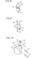
- the rotary pawl clutch 116 comprises a pawl base 118, at least one pawl 120 having a pawl head 121 pivotally mounted to the pawl base 118, a solenoid 122 mounted to the pawl base 118 and operably connected to the pawl 120 to actuate the pawl 120, and a ratchet-sprocket gear 124 engagable with the pawl 120.
- the solenoid 122 has an extendable and retractable solenoid arm 123 pivotally mounted to the pawl 120 to affect pivotal movement of the pawl 120 upon actuation of the solenoid 122.
- pawls 120 and solenoids 122 are utilized for each ratchet-sprocket gear 124 in the present invention. Even though only one pawl 120 and solenoid 122 set is needed for each ratchet-sprocket gear 124, a second set is provided for safety redundancy in the event one of the pawl 120 and solenoid 122 sets fails to operate.
- the pawl base 118 is fixedly mounted to and rotates with the drive shaft 114. As shown in Figure 12 , the pawl base 118 and the drive shaft 114 have mating key slots 119a and 119b, and a mating key 126 is inserted into the key slots 119a and 119b, locking the pawl base 118 to the drive shaft 114. Solenoid brackets 128 are mounted to the pawl base 118 to receive and hold the solenoids 122. A base openings 130 extend through the pawl base 118 to provide a conduit for electrical wiring 132 that is operably connected to the solenoids 122.
- the drive shaft 114 has a shaft openings 115 positioned such that the base openings 130 align with the shaft openings 115.
- the electrical wiring 132 extends through the base openings 130 and the shaft openings 115 into a hollow core 140 of the drive shaft 114. The electrical connections are discussed further below.
- the ratchet-sprocket gear 124 has a cylindrically shaped hollow 133, a ratchet wheel portion 134 and a sprocket portion 136.
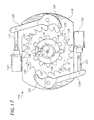
- the ratchet-sprocket gear 124 is rotatably mounted on the drive shaft 114 with the ratchet wheel portion adjacent the pawl base 118, as illustrated in Figure 11 .
- a bushing 138 such as a brass bushing, is disposed within the hollow 133 of the ratchet-sprocket gear 124 to rotatably engage the drive shaft 114.
- the ratchet wheel portion 134 has a plurality of substantially evenly spaced indentations 135 along the circumference thereof. As shown in Figure 14 , the indentations 135 are preferably substantially J-shaped.
- the ratchet-sprocket gear 124 is preferably positioned with the ratchet wheel portion 134 adjacent the pawl base 118.
- the chain 98 engages the sprocket portion 136 in a manner so that upward vertical movement of the respective, operably connected cable 72 provides clockwise rotation of the ratchet-sprocket gear 124 on the drive shaft 114, with respect to the illustrations shown in Figures 16 and 17 .
- the solenoid arm 123 is preferably normally biased in an extended position, thereby causing the pawl head 121 to engage one of the indentations 135, which prevents counterclockwise rotational movement of the ratchet-sprocket gear 124 with respect to the pawl base 118. Actuation of the solenoid 122 results in the solenoid arm 123 being retractable and the pawl 120 disengagable with the ratchet wheel portion 134, as shown in Figure 17 .
- the pawl head 121 can not disengage the indentation 135 to permit free rotation of the ratchet-sprocket gear 124 on the drive shaft 114 until the ratchet-sprocket gear 124 is initially rotated clockwise with respect to the pawl base 118.
- the respective, operably connected cable 72 must be initially retracted to permit both the pawl head 121 to disengage the respective indentation 135 of the ratchet wheel portion 134 and the solenoid arm 123 to retract and pivot the pawl head 121 outwardly from the ratchet-sprocket gear 124.
- the motor assembly 142 is exteriorly mounted to the frame 32 of the tower section 46.
- the motor assembly 142 comprises a reversible drive motor 144, a motor brake 146 and a reduction gear 148, all of which are conventional.
- the motor brake 146 is operably connected to the motor 144 to selectively prevent rotation of its motor shaft (not shown) and armature (not shown).
- the motor shaft is operably connected to the reduction gear 148, which is operably connected to the drive shaft 114. While the motor brake 146 is engaged, the drive shaft 114 is prohibited from rotational movement. Electrical actuation of the motor brake 146 is required to release the motor 144 prior to the drive shaft 114 being operable for rotational movement.
- loss of electrical power automatically causes the motor brake 146 to engage and prohibit rotational movement of the drive shaft 114.
- the solenoid arm 123 is biased in the extended position.
- loss of electrical power causes the solenoid arm 123 to extend and pivot the pawl 120, which causes the pawl head 121 to engage the ratchet-sprocket gear 124 and prevent counterclockwise rotation thereof.
- the motor brake 146 engages the motor 144, which prohibits rotational movement of the drive shaft 114.
- the pawl base 118 is fixedly mounted to the drive shaft 114, the ratchet-sprocket gear 124 is prohibited from counterclockwise movement on the drive shaft.
- the cable 72 is prohibited from extending from the boom 54, preventing downward vertical movement of the weight assembly.
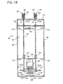
- FIG. 18 another embodiment of the rotary pawl clutch 116 is shown in use with the present invention.
- this embodiment there is one pawl base 118 for each ratchet-sprocket gear 124.
- This embodiment of the rotary paw clutch 116 operates in the same manner as described above.
- the pawl bases 118 are spaced apart on the drive shaft 114 which extends outwardly in both directions from the reduction gear 148.
- the reduction gear 148 is operably connected to the motor 144, which is mounted to the frame 32 within the tower section 46.
- the motor brake 146 is operably connected to the motor 144 and operates as described above.
- counterweight stops 150 are mounted to the frame 32 within the tower section 46 adjacent the sprocket shaft 102 and the drive shaft 114.
- the counterweight stops 150 are positioned to engage and block the counterweights 104 from contacting the sprocket gears 100 and the sprocket portions 136 of the sprocket-ratchet gears 124 while the chains 96 of the reciprocating drives are in reciprocating motion with the motor 144 disengaged and the rotatory pawl clutch 116 actuated.
- counterweight switches 152 are likewise mounted to the frame 32 within the tower section 46 adjacent the sprocket and drive shafts 102 and 114 proximate the chains 98. The counterweight switches 152 are operably and electrically connected to the motor 144.
- the electrical connections and switches of the present invention are conventional. However, the manner of use thereof is not conventional.
- An electrical junction enclosure 154 is provided to operably and electrically connect the switches generally to either the rotary pawl clutch 116 or the motor 144.
- the left and right hand switches 88A and 88B are operably connected to one another so that both hand switches 88A and 88B must be activated to actuate the solenoids 122 of the rotary pawl clutch 116.
- An override switch 156 is provided so that upon its activation the electrical connection from the hand switches 88 to the solenoids 122 is interrupted, which causes the pawls 120 to engage the ratchet-sprocket gear 124, and the motor 144 is simultaneously activated to retract the cables 72 and raise the weight assembly.
- male electrical connectors 158 are operably and electrically connected to additional electrical wiring 132 which is spiral wrapped around the respective cable 72 and operably and electrically connected to the enclosure 154.
- the male connector 158 removably engages the receptacle 82 and electrically connects the respective hand switch 88 to the enclosure 154 and the solenoids 122.
- electrical wiring 132 extends from each solenoid through the pawl base 118 into the core 140 of the drive shaft 114.
- the wiring is operably and electrically connected to the junction enclosure 154 by conventional means.
- the apparatus 30 is operative to assist a weightlifter in the use of dumbbells 26.
- the dumbbells 26 are suspended from the respective cables 72 by dumbbell clamps 160.
- Each dumbbell clamp 160 has a two spaced-apart plates 162 which are substantially identical in shape and are connected to one another by a post 164.
- the plates 162 have a notch 166 for receiving the grip 28 of the dumbbell 26.
- An elongated slot 168 intersects the notch 166. Slidably disposed within the slot 168 is a locking bar 170.
- Caps 172 are mounted to the locking bars 170 opposite one another and slidably engage the respective plates 162 adjacent the slots 168 to retain the locking bars 170 within the slots 168.
- a handle 174 is mounted to and extends between the locking bars 170.
- a spring 176 is disposed in each slot 168 to bias the locking bar 170 toward the notch 166 and removably engage the grip 28, thereby securing the grip 28 within the notch 166.
- a clamp bore 178 is provided to engage the J-hook and secure the dumbbell clamp 160 to the cable 72 as shown.
- the springs 176 force the locking bars 170 toward the notches 166 and engage the grip 28, securing the grip within the notches 170.
- Another hand switch 88 extends between the plates 162 proximate the notches 166.
- a female electrical receptacle 82 is operably connected to the hand switch 88.
- the male electrical connector 158 is removably connectable to the female receptacle 82.
- the hand switches 88 of both clamps 160 preferably must be engaged to actuate the pawls 120, thereby releasing the respective cables for independent reciprocating movement.
- an extension switch 180 and a retraction switch 182 are mounted to the frame 32 and operably connected to the motor assembly 142 for selectively extending and retracting the cables 72, respectively, while the hand switches 88 are not activated.
- Activation of the extension switch 180 releases the motor brake 146 and activates the motor 144 to rotate the drive shaft 144 in a direction to extend the cables 72 from the booms 54.
- activation of the retraction switch 182 releases the motor brake 146 and activates the motor 144 to rotate the drive shaft 114 in the opposite direction to retract the cables 72.
- electrical power to the motor 144 is interrupted and the motor brake 146 engages the motor 144, securing the drive shaft 114 from rotation.
- counterbalance weights having the same weight as the counterweights 104 are mounted to either the cables 72 or to the barbell 24 and the dumbbell clamps 160. As such, the weightlifter is lifting the true weight of the weight assembly as in free-weight fashion.
- the weightlifter depresses both hand switches 88 of the barbell 24 or the dumbbell clamps 160 to actuate the solenoids 122, which disengages the pawls 120 from the ratchet-sprocket gear 124 and releases the weight assembly for reciprocating vertical movement.
- the weightlifter releases either or both of the hand switches 88, thereby interrupting electrical power to the solenoids 122 and causing the pawls 120 to engage the ratchet-sprocket gear 124 to secure the cables 72 from vertical movement.
Landscapes
- Health & Medical Sciences (AREA)
- Life Sciences & Earth Sciences (AREA)
- Biophysics (AREA)
- Orthopedic Medicine & Surgery (AREA)
- General Health & Medical Sciences (AREA)
- Physical Education & Sports Medicine (AREA)
- Transmission Devices (AREA)
- Emergency Lowering Means (AREA)
- Jib Cranes (AREA)
- Heating, Cooling, Or Curing Plastics Or The Like In General (AREA)
- Lining Or Joining Of Plastics Or The Like (AREA)
- Special Conveying (AREA)
- Saccharide Compounds (AREA)
- Details Of Connecting Devices For Male And Female Coupling (AREA)
- Manufacturing Of Electrical Connectors (AREA)
Claims (17)
- Sicherheitsabsetzvorrichtung (30) zur Verwendung in Verbindung mit einer Freigewichtanordnung (22), wobei die Vorrichtung umfasst:einen Rahmen (32);ein erstes flexibles Seil (72A) mit einem ersten Ende, das lösbar an einem ersten Ende der Freigewichtanordnung (22) befestigt werden kann, undeinem zweiten Ende des ersten Seils (72A), das mit dem Rahmen wirksam verbunden ist;eine erste Sperrklinken- und Klinkenradanordnung (116A), die mit dem Rahmen (32) wirksam verbunden ist;ein zweites flexibles Seil (72B) mit einem ersten Ende, das an einem zweiten Ende der Freigewichtanordnung (22) lösbar befestigt werden kann, undeinem zweiten Ende des zweiten Seils (72B), das mit dem Rahmen wirksam verbunden ist;eine zweite Sperrklinken- und Klinkenradanordnung (116B), die mit dem Rahmen (32) wirksam verbunden ist;ein erstes Lösestellglied (88A) und ein zweites Lösestellglied (88B), die an der Freigewichtanordnung (22) montierbar sind und mit einem ersten Lösevorspannungselement (122A) an der ersten Sperrklinken- undKlinkenradanordnung (116A) und einem zweiten Lösevorspannungselement (122B) an der zweiten Sperrklinken- und Klinkenradanordnung (116B) wirksam verbunden sind;dadurch gekennzeichnet, dassdas zweite Ende des ersten Seils (72A) mit dem Rahmen (32) durch die erste Sperrklinken- und Klinkenradanordnung (116A) verbunden ist und das zweite Ende des zweiten Seils (72B) mit dem Rahmen (32) unabhängig von der ersten Sperrklinken- und Klinkenradanordnung (116A) durch die zweite Sperrklinken- und Klinkenradanordnung (116B) verbunden ist; und dass das erste Lösestellglied (88A) und das zweite Lösestellglied (88B) wirksam verbunden sind, um die Aktivierung sowohl des ersten Lösestellgliedes (88A) als auch des zweiten Lösestellgliedes (88B) zu erfordern, um das erste Lösevorspannungselement (122A) und das zweite Lösevorspannungselement (122B) zu aktivieren, wobei die Aktivierung sowohl des ersten Lösestellgliedes (88A) als auch des zweiten Lösestellgliedes (88B) eine Bewegung des ersten Seils (72A) und des zweiten Seils (72B) unabhängig voneinander ermöglicht.
- Sicherheitsabsetzvorrichtung nach Anspruch 1, welche ferner zwei Pendelantriebe (96) zum Anheben oder Absenken der Freigewichtanordnung (22) umfasst.
- Sicherheitsabsetzvorrichtung nach Anspruch 2, welche ferner einen Motor (144) umfasst, der mit den Pendelantrieben (96) wirksam verbunden ist.
- Sicherheitsabsetzvorrichtung nach einem vorangehenden Anspruch, wobei die erste Sperrklinken- und Klinkenradanordnung (116A) ein erstes Klinkenrad (134A) und eine erste Sperrklinke (120A) umfasst, die so vorgespannt ist, dass sie normalerweise mit dem ersten Klinkenrad (134A) in Eingriff steht.
- Sicherheitsabsetzvorrichtung nach einem vorangehenden Anspruch, wobei die zweite Sperrklinken- und Klinkenradanordnung (116B) ein zweites Klinkenrad (134B) und eine zweite Sperrklinke (120B) umfasst, die so vorgespannt ist, dass sie normalerweise mit dem zweiten Klinkenrad (134B) in Eingriff steht.
- Sicherheitsabsetzvorrichtung nach einem vorangehenden Anspruch, wobei das erste Lösevorspannungselement eine erste Magnetspule umfasst, die mit der ersten Sperrklinke (120A) verbunden ist, und das zweite Lösevorspannungselement (122B) eine zweite Magnetspule umfasst, die mit der zweiten Sperrklinke (120B) verbunden ist.
- Sicherheitsabsetzvorrichtung nach Anspruch 3, wobei die Sperrklinken- und Klinkenradanordnungen (116A, 116B) eine Kupplungseinrichtung (116) bilden.
- Sicherheitsabsetzvorrichtung nach Anspruch 7, wobei der Motor (144) eine Antriebswelle (114) aufweist, die bei der Betätigung des Motors (144) drehbar ist, und die Kupplungseinrichtung (116) umfasst:mindestens eine Sperrklinkenbasis (118), die an der Antriebswelle (114) montiert ist;mindestens zwei Klinkenrad-Kettenräder (124), die drehbar an der Antriebswelle (114) montiert sind und einen Klinkenradteil (134, 134A, 134B) und einen Kettenradteil (136) aufweisen; undmindestens zwei beabstandete betätigbare Sperrklinken (120, 120A, 120B), die drehbar an der mindestens einen Sperrklinkenbasis (118) montiert sind, wobei jede Sperrklinke (120, 120A, 120B) entfernbar mit dem jeweiligen Klinkenradteil (134, 134A, 134B) zum Sichern des Klinkenrad-Kettenrades (124) gegen eine Drehbewegung um die Drehwelle (114) in Eingriff steht undder Kettenradteil (136) mit dem jeweiligen Pendelantrieb (96) in Eingriff steht, wodurch die Betätigung der Sperrklinken (120, 120A, 120B) die Klinkenrad-Kettenräder (124) löst, um eine unabhängige Bewegung der jeweiligen Pendelantriebe (96) vorzusehen.
- Sicherheitsabsetzvorrichtung nach Anspruch 8, wobei die Lösevorspannungselemente (122, 122A, 122B) an der Sperrklinkenbasis (118) montiert sind und jeweils wirksam mit den mindestens zwei Sperrklinken (120, 120A, 120B) zum Betätigen der Sperrklinken (120, 120A, 120B) verbunden sind.
- Sicherheitsabsetzvorrichtung nach einem der Ansprüche 7 bis 9, wobei jeder Pendelantrieb (96) umfasst:ein Kettenrad (100), das drehbar am Rahmen (32) montiert ist; undeine Kette (98), die das Kettenrad (100) mit der Kupplung (116) beweglich koppelt.
- Sicherheitsabsetzvorrichtung nach einem der Ansprüche 3 bis 10, welche ferner eine Bremseinrichtung (146) umfasst, die mit dem Motor (144) wirksam verbunden ist.
- Sicherheitsabsetzvorrichtung nach einem der Ansprüche 2 bis 11, wobei das jeweilige Lösestellglied (88, 88A, 88B) einen Handschalter zum selektiven Betätigen der Sperrklinken- und Klinkenradanordnungen (116A, 116B) umfasst, um die Pendelantriebe (96) zu lösen.
- Sicherheitsabsetzvorrichtung nach Anspruch 12, welche ferner einen Übersteuerungsschalter (156) umfasst, der wirksam mit den Lösevorspannungselementen (122, 122A, 122B) verbunden ist, um den Handschalter (88) und den Motor (144) zum Betätigen des Motors (144) und Zurückziehen der Seile (72, 72A, 72B) wirksam zu trennen.
- Sicherheitsabsetzvorrichtung nach einem vorangehenden Anspruch, welche ferner eine Vorspannungseinrichtung (104) zum Aufrechterhalten der Spannung an den Seilen (72, 72A, 72B) umfasst.
- Sicherheitsabsetzvorrichtung nach Anspruch 10, welche ferner ein Gegengewicht (104) umfasst, das an der Kette (96) montiert ist, um die Spannung am Seil (72) aufrechtzuerhalten.
- Sicherheitsabsetzvorrichtung nach einem vorangehenden Anspruch, welche ferner zwei Ausleger (54) umfasst, die schwenkbar am Rahmen (32) montiert sind und einen Teil der jeweiligen Seile (72, 72A, 72B) beweglich aufhängen, so dass sich die Seile (72, 72A, 72B) normalerweise von der Freigewichtanordnung (22) nach oben erstrecken, wobei der Abstand zwischen den aufgehängten Teilen der Seile (72, 72A, 72B) variabel ist.
- Sicherheitsabsetzvorrichtung nach einem vorangehenden Anspruch, wobei die Freigewichtanordnung (22) ein Paar von Hanteln (26) ist und die Vorrichtung ferner Hantelklemmen (160) umfasst, die an den Seilen (72, 72A, 72B) zum lösbaren Eingriff mit den Hanteln (26) befestigt werden können, wobei jede Hantelklemme (160) umfasst:zwei beabstandete, im Wesentlichen identische Platten (162) mit einer Kerbe (166) zum Aufnehmen eines Griffs der Hantel (26) und einem länglichen Schlitz (168), der die Kerbe (166) schneidet, wobei eine Verriegelungsstange (170) verschiebbar in jedem Schlitz (168) angeordnet ist; undeine Vorspannungseinrichtung (176) zum Vorspannen der Verriegelungsstange (170) in Richtung des Schlitzes (168), wobei die Verriegelungsstangen (170) mit dem Griff in Eingriff kommen und diesen in der Kerbe (166) befestigen.
Applications Claiming Priority (3)
| Application Number | Priority Date | Filing Date | Title |
|---|---|---|---|
| US201434 | 1998-11-30 | ||
| US09/201,434 US6379287B1 (en) | 1998-11-30 | 1998-11-30 | Barbell and dumbbell safety spotting apparatus |
| PCT/US1999/028065 WO2000037144A1 (en) | 1998-11-30 | 1999-11-23 | Barbell and dumbbell safety spotting apparatus |
Publications (3)
| Publication Number | Publication Date |
|---|---|
| EP1133335A1 EP1133335A1 (de) | 2001-09-19 |
| EP1133335A4 EP1133335A4 (de) | 2004-08-04 |
| EP1133335B1 true EP1133335B1 (de) | 2008-08-06 |
Family
ID=22745803
Family Applications (1)
| Application Number | Title | Priority Date | Filing Date |
|---|---|---|---|
| EP99959098A Expired - Lifetime EP1133335B1 (de) | 1998-11-30 | 1999-11-23 | Sicherheitsvorrichtung zum Positionieren von Hanteln |
Country Status (9)
| Country | Link |
|---|---|
| US (3) | US6379287B1 (de) |
| EP (1) | EP1133335B1 (de) |
| CN (1) | CN1204938C (de) |
| AT (1) | ATE403472T1 (de) |
| AU (1) | AU1634100A (de) |
| CA (1) | CA2356626A1 (de) |
| DE (1) | DE69939271D1 (de) |
| MX (1) | MXPA01005435A (de) |
| WO (1) | WO2000037144A1 (de) |
Families Citing this family (144)
| Publication number | Priority date | Publication date | Assignee | Title |
|---|---|---|---|---|
| US6149948A (en) * | 1999-07-02 | 2000-11-21 | University Of Alabama | Method of decreasing plasma cholesterol and triglycerides with a chromium-containing complex |
| US6893381B2 (en) | 1999-08-28 | 2005-05-17 | Michael D. Slawinski | Self-spotting apparatus for free-weights |
| US6293892B1 (en) * | 1999-08-28 | 2001-09-25 | Prospot, Inc. | Self-spotting apparatus for free-weights |
| US6926649B2 (en) * | 1999-08-28 | 2005-08-09 | Michael D. Slawinski | Self-spotting apparatus for free-weights |
| US7169093B2 (en) * | 1999-09-14 | 2007-01-30 | Free Motion Fitness, Inc. | Cable crossover exercise apparatus |
| US6238323B1 (en) * | 1999-09-14 | 2001-05-29 | The Simonson Family Limited Partnership Rlllp | Cable crossover exercise apparatus |
| US6558299B1 (en) * | 2000-02-28 | 2003-05-06 | J. Patrick Slattery | Method and device for assisting weight lifters in performing weight lifting exercises |
| US6632159B1 (en) * | 2000-10-26 | 2003-10-14 | J. Patrick Slattery | Process and system for assisting weight lifters in performing weight lifting exercises |
| US7488277B1 (en) * | 2000-11-17 | 2009-02-10 | Knapp Jeffrey M | Compact weightlifting frame system |
| US20030045406A1 (en) * | 2001-08-28 | 2003-03-06 | Icon Ip,Inc. | Reorientable pulley system |
| US6905446B2 (en) * | 2002-01-17 | 2005-06-14 | Darrell Greenland | Exercise device |
| US7163488B2 (en) * | 2003-04-16 | 2007-01-16 | Anders Douglas H | Free weight assistance and training device |
| WO2005016457A2 (en) * | 2003-08-06 | 2005-02-24 | Slawinski Michael D | Combination free and stack-weight fitness apparatus |
| FR2859384B1 (fr) * | 2003-09-09 | 2006-09-01 | Guillaume Rolland | Appareil de musculation et/ou de reeducation avec une assistance variable et automatique par contrepoids |
| ITCZ20040001A1 (it) * | 2004-01-26 | 2004-04-26 | Salvatore Carbone | Attrezzo ginnico per allenamento dei muscoli pettorali, deltoidi, trapezi e tricipiti |
| KR200360382Y1 (ko) * | 2004-05-25 | 2004-08-31 | 배상욱 | 벤치 프레스 |
| US7585259B2 (en) * | 2005-01-24 | 2009-09-08 | Maxrep Benchcrafters Llc | Weightlifting spotting machine |
| US7228945B2 (en) * | 2005-03-16 | 2007-06-12 | Hr Textron, Inc. | Techniques for employing electric brakes to control movement of rotatable components |
| US7455629B2 (en) * | 2005-05-05 | 2008-11-25 | The Brinkmann Corporation | Exercise device with a safety lock |
| US7601105B1 (en) | 2005-07-11 | 2009-10-13 | Icon Ip, Inc. | Cable crossover exercise apparatus with lateral arm movement |
| US20070021270A1 (en) * | 2005-07-22 | 2007-01-25 | David Nugent | Athletic velocity training device |
| US20070072750A1 (en) * | 2005-09-26 | 2007-03-29 | Wasim Andrews | Weight lifting spotting device |
| ITRA20050043A1 (it) * | 2005-11-25 | 2007-05-26 | Technogym Spa | Macchina ginnica |
| USD550793S1 (en) * | 2006-01-05 | 2007-09-11 | Rogers Athletic Company | Weightlifting rack |
| US7918771B2 (en) * | 2006-01-05 | 2011-04-05 | Rogers Athletic Company | Weightlifting system with omni directional weight arms |
| USD551306S1 (en) | 2006-01-05 | 2007-09-18 | Rogers Athletic Company | Pair of horizontal weight arm assemblies for an exercise apparatus |
| USD547400S1 (en) | 2006-01-05 | 2007-07-24 | Rogers Athletic Company | Weight bench cushion arrangement |
| USD562670S1 (en) | 2006-01-05 | 2008-02-26 | Rogers Athletic Company | Weightlifting system lock and load bar support hook |
| US7465260B2 (en) * | 2006-01-05 | 2008-12-16 | Rogers Athletic Company | Weightlifting bench with synchronized backrest and seat |
| USD550792S1 (en) | 2006-01-05 | 2007-09-11 | Rogers Athletic Company | Pair of decline weight arm assemblies for an exercise apparatus |
| US7641602B2 (en) * | 2006-01-05 | 2010-01-05 | Rogers Athletic Company | Weightlifting system with positionable handles |
| USD550790S1 (en) | 2006-01-05 | 2007-09-11 | Rogers Athletic Company | Pad for an exercise apparatus |
| US7878958B2 (en) * | 2006-01-05 | 2011-02-01 | Rogers Athletic Company | Weightlifting system with spotter platform |
| US7322912B2 (en) * | 2006-01-05 | 2008-01-29 | Rogers Athletic Company | Weightlifting bench with adjustable headrest |
| USD554209S1 (en) | 2006-01-05 | 2007-10-30 | Rogers Athletic Company | Chin up bar assembly for an exercise apparatus |
| USD550791S1 (en) | 2006-01-05 | 2007-09-11 | Rogers Athletic Company | Pair of weight arm assemblies for an exercise apparatus |
| US8337370B2 (en) * | 2006-01-05 | 2012-12-25 | Rogers Athletic Company | Weightlifting support assembly |
| US20080004165A1 (en) * | 2006-02-28 | 2008-01-03 | Brawner William M | Self spotting barbell press |
| US20070203003A1 (en) * | 2006-02-28 | 2007-08-30 | Brawner William M | Self spotting barbell press |
| US20080070759A1 (en) * | 2006-04-21 | 2008-03-20 | Chaulk Mark E | Dumbbell Supporting Device |
| US20080020909A1 (en) * | 2006-07-12 | 2008-01-24 | Blair Constance L | Safety Assistance Strap with Bar Attachments |
| US20080182731A1 (en) * | 2007-01-25 | 2008-07-31 | Vittone Suzanne R | Centrifugal force machine |
| US7736286B2 (en) * | 2008-02-27 | 2010-06-15 | Jordan Panaiotov | Exercise system utilizing elastic bands |
| US7819785B2 (en) * | 2008-06-17 | 2010-10-26 | Maiaro Richard J | Safety device for spotting a user of a barbell without a need for human intervention |
| US9272179B2 (en) | 2009-10-26 | 2016-03-01 | The Personal Trainer, Inc. | Tension systems and methods of use |
| US8992385B2 (en) * | 2009-10-26 | 2015-03-31 | Personal Trainer, Inc. | Tension systems and methods of use |
| US8784281B2 (en) * | 2010-03-19 | 2014-07-22 | Iron Ally, LLC | Weight lifting free fall restraint system |
| US9421414B2 (en) | 2010-07-20 | 2016-08-23 | Lee Floyd | Exercise device |
| US8444537B1 (en) * | 2010-11-10 | 2013-05-21 | John G. Santoro | Cable and pulley weightlifting system apparatus |
| US8517900B1 (en) | 2011-03-17 | 2013-08-27 | Jeremy Britt | Barbell positioning system |
| US9327160B2 (en) | 2011-03-22 | 2016-05-03 | Jake Samuel Tauriainen | Modular self-spotting safety device for weightlifting |
| EP2712305B1 (de) * | 2011-05-17 | 2018-08-29 | Zimmer, Inc. | Externes befestigungsklemmsystem mit einem auslösemechanismus und gespeicherter federenergie |
| US8876672B2 (en) * | 2011-06-24 | 2014-11-04 | Mark Schiano | Method and apparatus for exercise device |
| US8827875B2 (en) * | 2011-06-24 | 2014-09-09 | Mark Schiano | Method and apparatus for exercise device |
| WO2013009749A1 (en) * | 2011-07-11 | 2013-01-17 | Powerblock Holdings, Inc. | Exercise machine for providing weight lifting exercises similar to those provided by a free weight barbell |
| US20140073493A1 (en) * | 2012-09-13 | 2014-03-13 | Beam's Industries, Inc. | Free weight support apparatus and method |
| USD731601S1 (en) * | 2013-02-27 | 2015-06-09 | 12Novem Industries, Inc. | Wheelchair-accessible exercise platform |
| EP2969058B1 (de) | 2013-03-14 | 2020-05-13 | Icon Health & Fitness, Inc. | Krafttrainingsvorrichtung mit schwungrad und zugehörige verfahren |
| ITMO20130152A1 (it) | 2013-05-28 | 2014-11-29 | Marco Giunchi | Macchina ginnica |
| US20150016919A1 (en) * | 2013-07-09 | 2015-01-15 | Dynamic Fitness & Strength, LLC | Fastener For Fitness Apparatus |
| US9610490B2 (en) * | 2013-10-29 | 2017-04-04 | Dynamic Fitness & Strength, LLC | Weight storage peg for fitness apparatus |
| CN103599623B (zh) * | 2013-10-30 | 2016-02-24 | 浙江工业大学 | 仰卧推举安全装置 |
| EP3086865B1 (de) | 2013-12-26 | 2020-01-22 | Icon Health & Fitness, Inc. | Mechanismus des magnetischen widerstands in einer kabelmaschine |
| US9504869B2 (en) * | 2014-01-13 | 2016-11-29 | Andrew Gavigan | Syn rings for dynamic weight suspension |
| USD735821S1 (en) * | 2014-01-24 | 2015-08-04 | Australian Fitness Suplies PTY Ltd | Foldable exercise apparatus |
| USD735820S1 (en) * | 2014-01-24 | 2015-08-04 | Australian Fitness Supplies Pty Ltd | Foldable exercise apparatus |
| US9333387B2 (en) | 2014-04-09 | 2016-05-10 | PRX Performance, Inc. | Retractable wall mounted exercise rack system |
| PL408062A1 (pl) * | 2014-04-29 | 2015-11-09 | Piotr Głuchowski | Urządzenie zapobiegające kontuzjom |
| WO2015191445A1 (en) | 2014-06-09 | 2015-12-17 | Icon Health & Fitness, Inc. | Cable system incorporated into a treadmill |
| US20160001123A1 (en) * | 2014-07-01 | 2016-01-07 | Anthony Roberts Parrish, JR. | Rowing machine suspension device |
| US9884239B2 (en) | 2015-03-15 | 2018-02-06 | John Gordon Kay | Portable, extensible, exercise weight support device with safety features |
| US10864400B2 (en) * | 2015-06-23 | 2020-12-15 | Kraftig Industries Pty Ltd | Exercise apparatus with movable vertical members |
| KR20170005739A (ko) * | 2015-07-06 | 2017-01-16 | 한태희 | 웨이트트레이닝 머신 |
| US10940360B2 (en) | 2015-08-26 | 2021-03-09 | Icon Health & Fitness, Inc. | Strength exercise mechanisms |
| TWI644702B (zh) | 2015-08-26 | 2018-12-21 | 美商愛康運動與健康公司 | 力量運動機械裝置 |
| CN108348802B (zh) * | 2015-11-13 | 2020-02-11 | 李炳敦 | 能够调节角度并能够摆动的史密斯机 |
| US10195479B2 (en) | 2016-02-19 | 2019-02-05 | Prx Performance, Llc | Retractable wall mounted weightlifting bench system |
| US10245461B2 (en) | 2016-03-16 | 2019-04-02 | Dave Peter Bruni | Strength training system and method of using same |
| US10293211B2 (en) | 2016-03-18 | 2019-05-21 | Icon Health & Fitness, Inc. | Coordinated weight selection |
| US10441840B2 (en) | 2016-03-18 | 2019-10-15 | Icon Health & Fitness, Inc. | Collapsible strength exercise machine |
| EP3222332A1 (de) * | 2016-03-24 | 2017-09-27 | Hocoma AG | Suspensionsvorrichtung zum auswuchten eines gewichts |
| US10080916B2 (en) * | 2016-03-31 | 2018-09-25 | Ki Won Lee | Fitness structure |
| US10252109B2 (en) | 2016-05-13 | 2019-04-09 | Icon Health & Fitness, Inc. | Weight platform treadmill |
| US10661112B2 (en) | 2016-07-25 | 2020-05-26 | Tonal Systems, Inc. | Digital strength training |
| US11745039B2 (en) | 2016-07-25 | 2023-09-05 | Tonal Systems, Inc. | Assisted racking of digital resistance |
| KR101819146B1 (ko) * | 2016-09-07 | 2018-01-16 | 주식회사 론픽 | 보조힘 판단이 가능한 운동보조장치 및 운동보조장치를 구비한 피지컬 피트니스 장비 |
| CN106422165B (zh) * | 2016-09-29 | 2018-12-14 | 施伟红 | 一种杠铃保护装置 |
| USD818547S1 (en) * | 2016-10-13 | 2018-05-22 | Hoist Fitness Systems, Inc. | Safety tier for exercise rack |
| US10661114B2 (en) | 2016-11-01 | 2020-05-26 | Icon Health & Fitness, Inc. | Body weight lift mechanism on treadmill |
| WO2018089624A1 (en) * | 2016-11-14 | 2018-05-17 | Specialty Fitness Systems, Llc | Weight ratio arrangement for a weight machine |
| US20230145445A1 (en) * | 2016-11-15 | 2023-05-11 | Initiate Launch, Llc | Kettle bell and methods of use thereof |
| US10532241B2 (en) * | 2016-11-15 | 2020-01-14 | Brian BOATNER | Kettle bell and methods of use thereof |
| US11433270B2 (en) * | 2017-11-15 | 2022-09-06 | Initiate Launch, Llc | Kettle bell and methods of use thereof |
| TWI672164B (zh) | 2016-12-05 | 2019-09-21 | 美商愛康運動與健康公司 | 跑步帶鎖定機構 |
| CN109200527A (zh) * | 2017-07-03 | 2019-01-15 | 刘克 | 安全杠铃 |
| US10486015B2 (en) | 2017-10-02 | 2019-11-26 | Tonal Systems, Inc. | Exercise machine enhancements |
| US10617903B2 (en) | 2017-10-02 | 2020-04-14 | Tonal Systems, Inc. | Exercise machine differential |
| US10589163B2 (en) | 2017-10-02 | 2020-03-17 | Tonal Systems, Inc. | Exercise machine safety enhancements |
| US10335626B2 (en) | 2017-10-02 | 2019-07-02 | Tonal Systems, Inc. | Exercise machine with pancake motor |
| US11660491B2 (en) | 2017-11-02 | 2023-05-30 | Coulter Ventures, Llc. | Weightlifting assembly |
| US10384096B1 (en) * | 2017-11-09 | 2019-08-20 | Christopher Aery | Weight assembly and associated use thereof |
| US10646744B2 (en) | 2018-03-02 | 2020-05-12 | Component Fabricators, Inc. | Pivoting weight arm assembly |
| CN108568053B (zh) * | 2018-04-24 | 2023-07-18 | 南京工业职业技术学院 | 一种防护性极强的杠铃式卧推装置 |
| USD888851S1 (en) | 2018-06-05 | 2020-06-30 | Coulter Ventures, Llc. | Wall mounted exercise rack |
| USD886920S1 (en) * | 2018-06-05 | 2020-06-09 | Coulter Ventures, Llc. | Set of wall mounts for exercise rack |
| USD879216S1 (en) | 2018-06-05 | 2020-03-24 | Coulter Ventures, Llc. | Wall mount |
| US11207556B2 (en) | 2018-07-23 | 2021-12-28 | Matthew Silveira | Competitive weightlifting machine and methods for using the same |
| CN108905059B (zh) * | 2018-07-25 | 2020-06-05 | 陈茹意 | 一种适用于哑铃推举初学者的稳定性训练设备 |
| CN108970012B (zh) * | 2018-08-31 | 2020-04-17 | 温州承玥机械设备有限公司 | 一种根据弯举程度调节重量的臂力健身器材 |
| CN109173145B (zh) * | 2018-09-28 | 2020-09-15 | 安阳师范学院 | 一种功能动作测评与训练器材 |
| CN109568878B (zh) * | 2018-11-08 | 2020-12-01 | 义乌市泽宣科技有限公司 | 一种防杠铃掉落的举重辅助架 |
| US10737134B2 (en) | 2018-11-13 | 2020-08-11 | Prx Performance, Llc | Wall-Mounted Collapsible Exercise System |
| US11123607B2 (en) * | 2019-01-11 | 2021-09-21 | James PADGETT | Exercise management and reporting system |
| US11298577B2 (en) | 2019-02-11 | 2022-04-12 | Ifit Inc. | Cable and power rack exercise machine |
| CN110051971A (zh) * | 2019-04-17 | 2019-07-26 | 盐城工业职业技术学院 | 一种可限位平衡杠铃 |
| WO2020243513A1 (en) | 2019-05-29 | 2020-12-03 | Bradley Davis | Barbell spotting apparatus |
| US10953301B2 (en) | 2019-06-10 | 2021-03-23 | Prx Performance, Llc | Folding exercise rack system |
| CN111228718B (zh) * | 2020-01-09 | 2021-05-18 | 唐山师范学院 | 一种下落过程可制动的力量举升器材 |
| CN111481877B (zh) * | 2020-04-22 | 2021-07-30 | 南京溧水高新产业股权投资有限公司 | 一种自动引导标准深蹲的深蹲架 |
| EP4146040A4 (de) * | 2020-05-04 | 2024-05-29 | Didyk, William | Dynamische arbeitsplatzvorrichtung, verfahren und systeme |
| US11285355B1 (en) | 2020-06-08 | 2022-03-29 | Tonal Systems, Inc. | Exercise machine enhancements |
| US11504570B2 (en) | 2020-06-23 | 2022-11-22 | Oxefit, Inc. | Strength training apparatus with multi-cable force production |
| CN112370730A (zh) * | 2020-11-30 | 2021-02-19 | 宜春职业技术学院 | 一种下腰辅助训练装置 |
| TWI755239B (zh) | 2021-01-05 | 2022-02-11 | 楊子岷 | 自由重量訓練保護裝置 |
| CN117098580A (zh) * | 2021-03-09 | 2023-11-21 | 科迪·奥斯汀·拉尼尔 | 马达驱动的升降架系统 |
| US12246211B2 (en) * | 2021-03-18 | 2025-03-11 | Michael P. Vaudreuil | Free weight harness system |
| US11058936B1 (en) | 2021-03-30 | 2021-07-13 | Prx Performance, Llc | Exercise rack enclosure system |
| US12194331B2 (en) * | 2021-04-09 | 2025-01-14 | Christopher S. O'CONNOR | Weightlifting apparatus with dynamic assist |
| US11446539B1 (en) | 2021-04-19 | 2022-09-20 | Prx Performance, Llc | Retractable wall mountable inclinable bench system |
| US11878204B2 (en) | 2021-04-27 | 2024-01-23 | Tonal Systems, Inc. | First repetition detection |
| US11998804B2 (en) | 2021-04-27 | 2024-06-04 | Tonal Systems, Inc. | Repetition phase detection |
| CN113230619A (zh) * | 2021-06-17 | 2021-08-10 | 成都拟合未来科技有限公司 | 智能健身安全保护方法 |
| US12214251B2 (en) | 2021-08-16 | 2025-02-04 | Prx Performance, Llc | Retractable exercise rack system |
| US11446535B1 (en) | 2021-11-04 | 2022-09-20 | Prx Performance, Llc | Folding exercise rack system |
| US11701540B2 (en) * | 2021-11-05 | 2023-07-18 | Eugene M. Wolf | Core trainer |
| CN114129958A (zh) * | 2021-12-08 | 2022-03-04 | 山东商务职业学院 | 一种具备防坠保护的体育教育用杠铃架 |
| US12274906B2 (en) * | 2022-10-28 | 2025-04-15 | Powerlifting Ultra Support Systems, LLC | Spotting system for weight lifting |
| CN117339166B (zh) * | 2023-10-26 | 2024-03-19 | 瑞柏生物(中国)股份有限公司 | 一种具有辅助结构的报警装置 |
| CN117356528A (zh) * | 2023-11-21 | 2024-01-09 | 会东县供销社和茧丝绸产业发展有限公司 | 一种便于调整蚕架高度的养蚕设备 |
| WO2025114240A1 (de) | 2023-11-27 | 2025-06-05 | Joest Michael | Halterung für einen zugseilarm |
| DE102023004869A1 (de) * | 2023-11-27 | 2025-05-28 | Michael JÖST | Halterung für einen Zugseilarm |
| EP4596058A1 (de) | 2024-02-05 | 2025-08-06 | Michael Jöst | Trainingsgerät mit zugschlitten |
| US20250360389A1 (en) * | 2024-05-21 | 2025-11-27 | Carter D. Kandow | Spotting System |
| US12415109B1 (en) * | 2025-01-10 | 2025-09-16 | Wall Home Inc | Foldable small flying and squat rack |
Citations (3)
| Publication number | Priority date | Publication date | Assignee | Title |
|---|---|---|---|---|
| US4998721A (en) * | 1989-04-18 | 1991-03-12 | Anders Douglas H | Weightlifter's exercising apparatus |
| DE3936377A1 (de) * | 1989-11-02 | 1991-05-08 | Becker Sport Fitnessprodukte G | Haltevorrichtung fuer eine freibewegbare hantelstange mit gewichten |
| WO1996009854A1 (en) * | 1994-09-28 | 1996-04-04 | Eugene Long | A weight lifting apparatus |
Family Cites Families (27)
| Publication number | Priority date | Publication date | Assignee | Title |
|---|---|---|---|---|
| US484352A (en) * | 1892-10-11 | Charles william aytoxst | ||
| US2603520A (en) * | 1950-04-08 | 1952-07-15 | Elmer E Brown | Gaff hook |
| US3888535A (en) * | 1974-06-21 | 1975-06-10 | Charles Rosso | Fireman{3 s pike pole or the like |
| US4253662A (en) * | 1979-02-05 | 1981-03-03 | Podolak Wayne S | Accessory apparatus for weight lifting |
| SU1233880A1 (ru) * | 1983-10-25 | 1986-05-30 | Московский областной государственный институт физической культуры | Устройство дл тренировки штангиста |
| US4765613A (en) | 1987-01-22 | 1988-08-23 | Paramount Fitness Equipment Corporation | Progressive resistance exercise device |
| US4799672A (en) | 1988-01-04 | 1989-01-24 | Barrett William L | Powerlift competition safety device |
| US4949959A (en) | 1989-10-10 | 1990-08-21 | Stevens William E | Barbell assist device |
| US5048826A (en) | 1990-08-23 | 1991-09-17 | Ryan William C | Safety apparatus for use with barbell assembly |
| US5411459A (en) | 1990-12-03 | 1995-05-02 | Hayden; Richard C. | Dumbbell rack attachment for exercise weight bench column |
| US5616108A (en) | 1990-12-03 | 1997-04-01 | Hayden; Richard C. | Dumbbell support attachment for barbell cross bar |
| US5151072A (en) | 1991-05-14 | 1992-09-29 | Cone Dennis E | Free weight barbell spotting and racking machine |
| US5431609A (en) | 1991-07-11 | 1995-07-11 | Panagiotopoulos; Anastasios | Electrical resistance exercise device with lift assistance |
| US5314394A (en) | 1991-12-31 | 1994-05-24 | Ronan John J | Spotting apparatus for assisting a weightlifter |
| US5273506A (en) | 1992-06-15 | 1993-12-28 | Dawson Jr Fredric O | Self spotting exercise apparatus |
| US5310394A (en) | 1992-12-28 | 1994-05-10 | Demetrios Kallios | Spotter system for weightlifters |
| US5407403A (en) * | 1993-09-10 | 1995-04-18 | Coleman; Vernon | Forced repetition assist device |
| US5823921A (en) * | 1994-03-11 | 1998-10-20 | Dawson; Jeffrey S. | Freeweight barbell lifting exercise machine with user controllable lift assist and safety device |
| US5468203A (en) | 1994-08-01 | 1995-11-21 | Okonkwo; Charles U. | Weight lifting safety device |
| US5573484A (en) | 1995-02-27 | 1996-11-12 | M. Michael Carpenter | Weighted auxiliary handle for dumbbell |
| US5549531A (en) | 1995-02-28 | 1996-08-27 | Campbell; Matthew W. | Weightlifting machine with safety device |
| US5989166A (en) * | 1995-11-13 | 1999-11-23 | Concepts 2000, Inc. | Adjustable barbell press apparatus |
| US5651758A (en) * | 1996-07-12 | 1997-07-29 | Cervantes; Juan C. | Dumbbell supporter |
| US5716306A (en) | 1996-10-25 | 1998-02-10 | Gallay; Sherman | Free weight self spotting apparatus |
| US5979840A (en) * | 1997-04-11 | 1999-11-09 | Hollister; Ronald S. | Apparatus for gripping a fluid carrying hose |
| US6261205B1 (en) | 1999-06-17 | 2001-07-17 | Patrick M. Elefson | Resistance training apparatus |
| US6893381B2 (en) * | 1999-08-28 | 2005-05-17 | Michael D. Slawinski | Self-spotting apparatus for free-weights |
-
1998
- 1998-11-30 US US09/201,434 patent/US6379287B1/en not_active Expired - Lifetime
-
1999
- 1999-11-23 WO PCT/US1999/028065 patent/WO2000037144A1/en not_active Ceased
- 1999-11-23 DE DE69939271T patent/DE69939271D1/de not_active Expired - Fee Related
- 1999-11-23 MX MXPA01005435A patent/MXPA01005435A/es active IP Right Grant
- 1999-11-23 EP EP99959098A patent/EP1133335B1/de not_active Expired - Lifetime
- 1999-11-23 CA CA002356626A patent/CA2356626A1/en not_active Abandoned
- 1999-11-23 CN CNB998151254A patent/CN1204938C/zh not_active Expired - Fee Related
- 1999-11-23 AU AU16341/00A patent/AU1634100A/en not_active Abandoned
- 1999-11-23 AT AT99959098T patent/ATE403472T1/de not_active IP Right Cessation
-
2002
- 2002-03-18 US US10/100,673 patent/US6669607B2/en not_active Expired - Lifetime
-
2003
- 2003-10-29 US US10/697,633 patent/US7374515B2/en not_active Expired - Fee Related
Patent Citations (3)
| Publication number | Priority date | Publication date | Assignee | Title |
|---|---|---|---|---|
| US4998721A (en) * | 1989-04-18 | 1991-03-12 | Anders Douglas H | Weightlifter's exercising apparatus |
| DE3936377A1 (de) * | 1989-11-02 | 1991-05-08 | Becker Sport Fitnessprodukte G | Haltevorrichtung fuer eine freibewegbare hantelstange mit gewichten |
| WO1996009854A1 (en) * | 1994-09-28 | 1996-04-04 | Eugene Long | A weight lifting apparatus |
Also Published As
| Publication number | Publication date |
|---|---|
| WO2000037144A1 (en) | 2000-06-29 |
| US20040092369A1 (en) | 2004-05-13 |
| AU1634100A (en) | 2000-07-12 |
| CN1346293A (zh) | 2002-04-24 |
| MXPA01005435A (es) | 2003-03-27 |
| DE69939271D1 (de) | 2008-09-18 |
| US6669607B2 (en) | 2003-12-30 |
| US6379287B1 (en) | 2002-04-30 |
| EP1133335A1 (de) | 2001-09-19 |
| US20020147081A1 (en) | 2002-10-10 |
| EP1133335A4 (de) | 2004-08-04 |
| ATE403472T1 (de) | 2008-08-15 |
| CN1204938C (zh) | 2005-06-08 |
| US7374515B2 (en) | 2008-05-20 |
| CA2356626A1 (en) | 2000-06-29 |
Similar Documents
| Publication | Publication Date | Title |
|---|---|---|
| EP1133335B1 (de) | Sicherheitsvorrichtung zum Positionieren von Hanteln | |
| US6293892B1 (en) | Self-spotting apparatus for free-weights | |
| US9327160B2 (en) | Modular self-spotting safety device for weightlifting | |
| US6893381B2 (en) | Self-spotting apparatus for free-weights | |
| US5989166A (en) | Adjustable barbell press apparatus | |
| EP1212122B1 (de) | Trainungsgerät mit Kabelüberführung | |
| US4902006A (en) | Arm exercise apparatus | |
| US4765610A (en) | Accessory for weightlifting equipment | |
| US9884239B2 (en) | Portable, extensible, exercise weight support device with safety features | |
| US7086991B2 (en) | Rope climbing simulator | |
| US11712593B2 (en) | Exercise bar carriage locking mechanism | |
| US5788616A (en) | Mechanical weightlifting machine | |
| US20070179030A1 (en) | Combination free and stack-weight fitness apparatus | |
| US5098361A (en) | Center supported weight lifting bars | |
| WO2005000423A1 (en) | Self-spotting apparatus for free-weights | |
| US4799670A (en) | Exercise apparatus | |
| CN100423800C (zh) | 组合自由和叠置重块健身设备 | |
| JPH0246928Y2 (de) | ||
| WO2021173717A1 (en) | Biceps exercise device and methods of use | |
| CN114470622A (zh) | 具自动化重量选择器的健身器材 |
Legal Events
| Date | Code | Title | Description |
|---|---|---|---|
| PUAI | Public reference made under article 153(3) epc to a published international application that has entered the european phase |
Free format text: ORIGINAL CODE: 0009012 |
|
| 17P | Request for examination filed |
Effective date: 20010525 |
|
| AK | Designated contracting states |
Kind code of ref document: A1 Designated state(s): AT BE CH CY DE DK ES FI FR GB GR IE IT LI LU MC NL PT SE |
|
| A4 | Supplementary search report drawn up and despatched |
Effective date: 20040617 |
|
| RIC1 | Information provided on ipc code assigned before grant |
Ipc: 7A 63B 21/078 B Ipc: 7A 63B 21/072 A |
|
| RTI1 | Title (correction) |
Free format text: BARBELL AND DUMBBELL SAFETY SPOTTING APPARATUS |
|
| GRAP | Despatch of communication of intention to grant a patent |
Free format text: ORIGINAL CODE: EPIDOSNIGR1 |
|
| GRAS | Grant fee paid |
Free format text: ORIGINAL CODE: EPIDOSNIGR3 |
|
| GRAA | (expected) grant |
Free format text: ORIGINAL CODE: 0009210 |
|
| AK | Designated contracting states |
Kind code of ref document: B1 Designated state(s): AT BE CH CY DE DK ES FI FR GB GR IE IT LI LU MC NL PT SE |
|
| REG | Reference to a national code |
Ref country code: GB Ref legal event code: FG4D |
|
| REG | Reference to a national code |
Ref country code: CH Ref legal event code: EP |
|
| REG | Reference to a national code |
Ref country code: IE Ref legal event code: FG4D |
|
| REF | Corresponds to: |
Ref document number: 69939271 Country of ref document: DE Date of ref document: 20080918 Kind code of ref document: P |
|
| PG25 | Lapsed in a contracting state [announced via postgrant information from national office to epo] |
Ref country code: NL Free format text: LAPSE BECAUSE OF FAILURE TO SUBMIT A TRANSLATION OF THE DESCRIPTION OR TO PAY THE FEE WITHIN THE PRESCRIBED TIME-LIMIT Effective date: 20080806 Ref country code: ES Free format text: LAPSE BECAUSE OF FAILURE TO SUBMIT A TRANSLATION OF THE DESCRIPTION OR TO PAY THE FEE WITHIN THE PRESCRIBED TIME-LIMIT Effective date: 20081117 |
|
| PG25 | Lapsed in a contracting state [announced via postgrant information from national office to epo] |
Ref country code: FI Free format text: LAPSE BECAUSE OF FAILURE TO SUBMIT A TRANSLATION OF THE DESCRIPTION OR TO PAY THE FEE WITHIN THE PRESCRIBED TIME-LIMIT Effective date: 20080806 Ref country code: AT Free format text: LAPSE BECAUSE OF FAILURE TO SUBMIT A TRANSLATION OF THE DESCRIPTION OR TO PAY THE FEE WITHIN THE PRESCRIBED TIME-LIMIT Effective date: 20080806 |
|
| PG25 | Lapsed in a contracting state [announced via postgrant information from national office to epo] |
Ref country code: BE Free format text: LAPSE BECAUSE OF FAILURE TO SUBMIT A TRANSLATION OF THE DESCRIPTION OR TO PAY THE FEE WITHIN THE PRESCRIBED TIME-LIMIT Effective date: 20080806 |
|
| PG25 | Lapsed in a contracting state [announced via postgrant information from national office to epo] |
Ref country code: DK Free format text: LAPSE BECAUSE OF FAILURE TO SUBMIT A TRANSLATION OF THE DESCRIPTION OR TO PAY THE FEE WITHIN THE PRESCRIBED TIME-LIMIT Effective date: 20080806 |
|
| PG25 | Lapsed in a contracting state [announced via postgrant information from national office to epo] |
Ref country code: PT Free format text: LAPSE BECAUSE OF FAILURE TO SUBMIT A TRANSLATION OF THE DESCRIPTION OR TO PAY THE FEE WITHIN THE PRESCRIBED TIME-LIMIT Effective date: 20090106 |
|
| PLBE | No opposition filed within time limit |
Free format text: ORIGINAL CODE: 0009261 |
|
| STAA | Information on the status of an ep patent application or granted ep patent |
Free format text: STATUS: NO OPPOSITION FILED WITHIN TIME LIMIT |
|
| PG25 | Lapsed in a contracting state [announced via postgrant information from national office to epo] |
Ref country code: MC Free format text: LAPSE BECAUSE OF NON-PAYMENT OF DUE FEES Effective date: 20081130 |
|
| REG | Reference to a national code |
Ref country code: CH Ref legal event code: PL |
|
| 26N | No opposition filed |
Effective date: 20090507 |
|
| GBPC | Gb: european patent ceased through non-payment of renewal fee |
Effective date: 20081123 |
|
| REG | Reference to a national code |
Ref country code: IE Ref legal event code: MM4A |
|
| PG25 | Lapsed in a contracting state [announced via postgrant information from national office to epo] |
Ref country code: IT Free format text: LAPSE BECAUSE OF FAILURE TO SUBMIT A TRANSLATION OF THE DESCRIPTION OR TO PAY THE FEE WITHIN THE PRESCRIBED TIME-LIMIT Effective date: 20080806 |
|
| REG | Reference to a national code |
Ref country code: FR Ref legal event code: ST Effective date: 20090731 |
|
| PG25 | Lapsed in a contracting state [announced via postgrant information from national office to epo] |
Ref country code: LI Free format text: LAPSE BECAUSE OF NON-PAYMENT OF DUE FEES Effective date: 20081130 Ref country code: IE Free format text: LAPSE BECAUSE OF NON-PAYMENT OF DUE FEES Effective date: 20081123 Ref country code: DE Free format text: LAPSE BECAUSE OF NON-PAYMENT OF DUE FEES Effective date: 20090603 Ref country code: CH Free format text: LAPSE BECAUSE OF NON-PAYMENT OF DUE FEES Effective date: 20081130 |
|
| PG25 | Lapsed in a contracting state [announced via postgrant information from national office to epo] |
Ref country code: GB Free format text: LAPSE BECAUSE OF NON-PAYMENT OF DUE FEES Effective date: 20081123 |
|
| PG25 | Lapsed in a contracting state [announced via postgrant information from national office to epo] |
Ref country code: SE Free format text: LAPSE BECAUSE OF FAILURE TO SUBMIT A TRANSLATION OF THE DESCRIPTION OR TO PAY THE FEE WITHIN THE PRESCRIBED TIME-LIMIT Effective date: 20081106 |
|
| PG25 | Lapsed in a contracting state [announced via postgrant information from national office to epo] |
Ref country code: LU Free format text: LAPSE BECAUSE OF NON-PAYMENT OF DUE FEES Effective date: 20081123 |
|
| PG25 | Lapsed in a contracting state [announced via postgrant information from national office to epo] |
Ref country code: CY Free format text: LAPSE BECAUSE OF FAILURE TO SUBMIT A TRANSLATION OF THE DESCRIPTION OR TO PAY THE FEE WITHIN THE PRESCRIBED TIME-LIMIT Effective date: 20080806 |
|
| PG25 | Lapsed in a contracting state [announced via postgrant information from national office to epo] |
Ref country code: GR Free format text: LAPSE BECAUSE OF FAILURE TO SUBMIT A TRANSLATION OF THE DESCRIPTION OR TO PAY THE FEE WITHIN THE PRESCRIBED TIME-LIMIT Effective date: 20081107 |
|
| PG25 | Lapsed in a contracting state [announced via postgrant information from national office to epo] |
Ref country code: FR Free format text: LAPSE BECAUSE OF NON-PAYMENT OF DUE FEES Effective date: 20081130 |