FIELD OF THE INVENTION
The present invention relates to an angular velocity sensor used for the
attitude control and navigation system of such moving bodies as an aircraft and vehicle.
BACKGROUND OF THE INVENTION
Known as this type of conventional angular velocity sensor is that disclosed
in Japanese Patent Application Non-examined Publication No. H08-170917.
Such a conventional angular velocity sensor is hereinafter explained with
reference to the drawings.
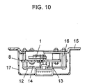
Fig. 9 shows a perspective view of the conventional angular velocity sensor
showing that a tuning fork is secured to a base; and Fig. 10 is a sectional side elevation
view of the same angular velocity sensor.
In Figs. 9 and 10, columnar tuning fork 1 is composed of a pair of columns 2
and joint 3 connecting the ends of this pair of columns 2 together. Provided on each of
the outer side faces of the pair of columns 2 of tuning fork 1 is driving piezoelectric
elements 4. In addition, provided on the side faces coplanar with those having driving
piezoelectric elements 4 are reference piezoelectric elements 5. Moreover, provided on
the side faces different from those having driving piezoelectric elements 4 and reference
piezoelectric elements 5 are a pair of detecting piezoelectric elements 6. Metallic
supporting member 7 supports the base of joint 3 of tuning fork 1. The bottom face of
supporting member 7 is secured to the top face of metallic base 8, and this base 8 also has a
plurality of terminal-insertion holes 9 therein. Terminals 10 pass through these terminal-insertion
holes 9 via insulators 11 and electrically connect to driving piezoelectric elements
4, reference piezoelectric elements 5, and detecting piezoelectric elements 6 of tuning fork
1. Circuit board 12 is provided under base 8 and connected to leads 13 by soldering that
are electrically connected to terminals 10 through base 8. The circuit board 12 also has
electronic components 14 mounted thereon for processing output signal generated by
angular velocity from detecting piezoelectric elements 6 on tuning fork 1. Supporting
base 15 supports base 8 and circuit board 12 using stud bolt 16. Metallic cover 17 houses
tuning fork 1, base 8 and circuit board 12 therein and covers supporting base 15.
The operation of the conventional angular velocity sensor constructed as
above is described below.
Applying alternative voltages to driving piezoelectric elements 4 on tuning
fork 1 allows tuning fork 1 to perform flexural vibration at its characteristic frequency in
the driven direction and at a speed of V in the driven direction. When tuning fork 1
rotates at an angular velocity of ω around the central axis of tuning fork 1 in this condition,
a Coriolis force of F = 2mv·ω is generated in the pair of columns 2 of tuning fork 1, where
m is the effective mass of the tuning fork. With this angular velocity sensor, angular
velocity were detected by the following steps: amplifying the electric charges generated by
the Coriolis force in detecting piezoelectric elements 6 using electronic components 14 on
circuit board 12; and measuring the electric charges as output voltages, using an external
computer.
However, with the above-mentioned conventional structure, base 8 and
circuit board 12 are connected to supporting base15 via stud bolt 16 as shown in Fig. 10
and thus external vibrations are applied to the sensor via this stud bolt 16. Such external
vibrations are applied to tuning fork 1 and may generate electric charges in detecting
piezoelectric elements 6 on tuning fork 1 even when no angular velocity is applied to the
angular velocity sensor. As a result, the angular velocity sensor has a problem of
deterioration of its output characteristics.
The present invention addresses the above-mentioned problem and aims to
provide an angular velocity sensor in which only little vibration is applied to its tuning fork
composed of first oscillator and second oscillator even when external vibration is applied
to the sensor with no angular velocity sensors applied thereto and thus allows the
prevention of deterioration of its output.
SUMMARY OF THE INVENTION
The angular velocity sensor of the present invention has a tuning fork
outputting a signal responsive to angular velocity; a first base for securing a part of the
tuning fork to the top face of the base; a first cover for covering the tuning fork together
with the first base; a second rubber body in contact with the top face of the first cover; a
first rubber body having a top face in contact with the bottom face of the first base; a
supporting plate having a top face in contact with the bottom face of the first rubber body;
a second base provided under the supporting plate; a tubular second cover having a bottom
and housing the tuning fork, the first base, the first cover, the second rubber body, the first
rubber body, and the supporting plate together with the second base. The first and second
rubber bodies are compressed and held by the top face of the supporting plate and the inner
ceiling of the second cover.
Also the angular velocity sensor of the present invention has a first oscillator
having at least one driving electrode or detecting electrode; a second oscillator having at
least one detecting electrode or driving electrode; a joint connecting one end of the first
oscillator and one end of the second oscillator; a first base for securing the joint thereon
and having at least three terminal-insertion holes for passing through at least three
terminals electrically connected to the driving electrode or detecting electrode; a first cover
secured to the top face of this first base for covering the first and second oscillators and the
joint; a first rubber body having a top face in contact with the bottom face of the first base;
a second rubber body in contact with the top face of the first cover; a circuit board
provided under the first base and having electronic components for processing output
signals generated by angular velocity from the detecting electrode, and a power-supply
terminal, ground terminal, and output terminal projecting downwardly; a second base
provided under the circuit board and having through holes for passing and securing the
power-supply terminal, ground terminal, and output terminal; and a second tubular cover
having a bottom secured to the top face of the second base and covering the first base, first
cover, first rubber body, second rubber body, and circuit board. A supporting plate having
a placement part on the top face thereof for placing the first rubber body is provided above
the top face of the second base so as to provide a space between the top face of the second
base and the supporting plate. The top face of this supporting plate and the inner ceiling
of the second cover compress the first rubber body and second rubber body.
With this structure, a supporting plate having a placement part on the top face
thereof for placing the first rubber body is provided above the top face of the second base
so as to provide a space between the top face of the second base and the supporting plate
via at least two supports and the top face of this supporting plate and the inner ceiling of
the second cover compress the first rubber body and second rubber body. Therefore, the
first base and the first cover housing the first and second oscillators therein are securely
supported by the first and second rubber bodies. Consequently, even when external
vibrations are applied to the angular velocity sensor, these oscillators transferred to the first
and second oscillators are reduced.
Also the angular velocity sensor of the present invention has a first recess
provided on the bottom face of the second rubber body and a step provided in the inner
ceiling of the first recess. The bottom face of this step and the top face of the first cover
are brought into contact with each other. In addition, second recesses projecting
outwardly are provided on the inner side faces of the first recess. With this structure, the
bottom face of the step in the inner ceiling of the first recess in the second rubber body is
in contact with the top face of the first cover and the portions provided on the inner side
faces of the first recess other than the second recesses are in contact with the outer side
faces of the first cover. Such contact reduces the area in which the second rubber body
and the first cover are in contact with each other and thus the second rubber body
attenuates external vibrations transferred to the first and second oscillators of the angular
velocity sensor.
For the angular velocity sensor of the present invention, the second rubber
body has the first recess shaped to a rectangular parallelepiped, a step provided on the
outer periphery of the inner ceiling of the first recess, and second recesses provided in the
portions along long sides of the first recess other than the edges thereof. The first cover is
also shaped to a rectangular parallelepiped having an opening at the bottom face thereof.
Then the step in the second rubber body is brought into contact with the outer periphery of
the top face of the first cover and the edges of the long sides of the first recess provided in
the second rubber body is brought into contact with the outer side faces of the first cover.
With this structure, the first cover is brought into contact with the second rubber body only
on the outer periphery of the top face and edges of the outer side faces thereof. As a
result, even when external rotational shocks are applied to the angular velocity sensor, the
first cover is rarely rotated by the rotational shocks because the cover is secured to the
second rubber body on the outer periphery of the top face and edges of outer side faces
thereof.
The angular velocity sensor of the present invention also has escapes for
receiving at least three terminals through the first base, in the first rubber body thereof.
The terminals through the first base are housed in the escapes in the first rubber body and
such a structure enables downsizing of the sensor.
The angular velocity sensor of the present invention also has notches for
positioning at least two supports, in the side faces of the circuit board thereof. The
supports of the supporting plate fit into the notches and such a structure prevents the
supporting plate from moving even when strong lateral vibrations are applied to the
angular velocity sensor.
For the angular velocity sensor of the present invention, the first base and the
first cover are secured to each other so as to create a vacuum in the interior space formed
therebetween. This structure reduces the air resistance in the interior space between the
first base and the first cover and thus facilitates the vibration of first and second oscillators
and improves the output sensitivity of the angular velocity sensor.
For the angular velocity sensor of the present invention, at least two supports
of the supporting plate have broad-shouldered portions having a width larger than that of
the notches. This structure prevents the supports from coming off from the circuit board,
even when external vertical impulsive force is applied to the angular velocity sensor. As a
result, the first and second oscillators are securely supported and thus the output of the
angular velocity sensor is stabilized.
BRIEF DESCRIPTION OF THE DRAWINGS
Fig. 1 is an exploded perspective view of an angular velocity sensor in
accordance with an exemplary embodiment of the present invention;
Fig. 2 is a sectional side elevation view of the same angular velocity sensor;
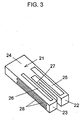
Fig. 3 is a perspective view of a first oscillator, a second oscillator and a joint
of the same angular velocity sensor;
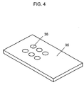
Fig. 4 is a perspective view of a first rubber body of the same angular
velocity sensor;
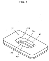
Fig. 5 is a perspective view of a second rubber body of the same angular
velocity sensor;
Fig. 6 is a perspective view of a circuit board of the same angular velocity
sensor;
Fig. 7 is a perspective view of a supporting plate of the same angular velocity
sensor;
Fig. 8 is a graph showing transfer characteristics of vibration varying with
areas in which the second rubber body is in contact with the first cover in the same angular
velocity sensor;
Fig. 9 is a perspective view of a conventional angular velocity sensor
showing that a tuning fork is secured to a base; and
Fig. 10 is a sectional side elevation view of the conventional angular velocity
sensor.
DESCRIPTION OF THE PREFERRED EMBODIMENTS
An angular velocity sensor in accordance with a preferred embodiment of the
present invention is hereinafter explained with reference to the accompanying drawings.
Fig. 1 is an exploded perspective view of an angular velocity sensor in
accordance with an exemplary embodiment of the present invention; Fig. 2 is a sectional
side elevation view of the same angular velocity sensor; Fig. 3 is a perspective view of a
first oscillator, a second oscillator and a joint of the same angular velocity sensor; Fig. 4 is
a perspective view of a first rubber body of the same angular velocity sensor; Fig. 5 is a
perspective view of a second rubber body of the same angular velocity sensor; Fig. 6 is a
perspective view of a circuit board of the same angular velocity sensor; and Fig. 7 is a
perspective view of a supporting plate of the same angular velocity sensor. Only the
second rubber body of Fig. 5 is shown as seen from the bottom so as to be understood
easily.
As shown in Figs. 1 through 7, crystal tuning fork 21 is composed of first
oscillator 22 of a square pole shape, second oscillator 23 of a square pole shape provided in
parallel with the first oscillator 22, and joint 24 integrally connecting one end of first
oscillator 22 to one end of second oscillator 23. Driving electrode 25 made of gold is
provided on each of the four side faces of first oscillator 22. Monitoring electrode 26
made of gold is provided on the upper side face of second oscillator 23. In addition,
provided on the inner side face of second oscillator 23 (the face opposite first oscillator 22)
is ground electrode (not shown). Moreover, a pair of detecting electrodes 28 made of
gold are provided on the outer side face. Metallic supporting base 29 shaped to a
rectangular parallelepiped supports the base of joint 24 of tuning fork 21. Metallic first
base 30 fixes the bottom of supporting base 29 and also has six terminal-insertion holes 31,
inner surface of each of which has insulator 32 made of glass. Six terminals 33 pass
through terminal-insertion holes 31 of first base 30 via insulators 32. Terminals 33
through first base 30 are electrically connected to driving electrodes 25, detecting
electrodes 28, ground electrode 27, and monitoring electrode 26, respectively, via leads
(not shown). Metallic first cover 34 is provided to cover the top face of first base 30.
First cover 34 and first base 30 house tuning fork 21 including first oscillator 22, second
oscillator 23 and joint 24 therein. In this case, first cover 34 and first base30 are in close
contact with each other so as to create a vacuum in the interior space formed between first
base 30 and first cover 34. Thus, first base 30 and first cover 34 are secured to each other
so as to create a vacuum in the interior space therebetween and this structure eliminates air
resistance of the interior space between first base 30 and first cover 34. As a result, first
oscillator 22 and second oscillator 23 oscillate easily and this is effective in improving the
output sensitivity of the angular velocity sensor.
The first oscillator may have at least one of driving electrode and detecting
electrode and the second oscillator may have at least one of detecting electrode and driving
electrode.
First rubber body 35 is provided so that its top face is in contact with the
bottom face of first base 30. Moreover, first rubber body 35 has escapes 36 for receiving
six terminals 33 through first base 30. Since escapes 36 for receiving six terminals 33
through first base 30 are provided in first rubber body 35 as mentioned above, terminals 33
through first base 30 are housed in escapes 36 in first rubber body 35. This structure
enables downsizing of the angular velocity sensor.
Second rubber body 37 is provided so as to be in contact with the top face of
first cover 34. Fig. 5 shows a perspective view of the second rubber body seen from its
bottom. The bottom face of second rubber body 37 has first recess 38 shaped to a
rectangular parallelepiped. Moreover, the inner ceiling of first recess 38 has step 39 on
outer periphery thereof. The step 39 is brought in contact with the top face of first cover
34. Second rubber body 37 has second recesses 40 protruding outwardly on the inner side
faces of the second rubber body. The edges 41a of long sides 41 in the portions other than
second recesses 40 are brought into contact with the outer side faces of first cover 34.
Circuit 42 is provided under first base 30 and has electronic components 43 on top and
bottom faces thereof. Output signal of electric charges generated by angular velocity
from detecting electrodes 28 on second oscillator 23 are supplied to electronic components
43 via terminals 33 and flexible wiring board 44, and electronic components 43 convert the
output signals of electric charges into output voltage. Circuit board 42 has four notches
45 in the side faces and terminal-insertion holes 46. Power-supply terminal 47, ground
terminal 48, and output terminal 49 project downwardly through these terminal-insertion
holes 46 and are soldered thereto.
Second base 50 is provided under circuit board 42 and also has four through
holes 51. Power-supply terminal 47, ground terminal 48, and output terminal 49 pass
through these through holes 51 via insulators 52 made of glass. Tubular second cover 53
with a bottom is secured to the top face of second base 50 and covers first base 30, first
cover 34, first rubber body 35, second rubber body 37 and circuit board 42. Metallic
supporting plate 54 is placed above the top face of second base 50 via supports 55 and thus
provides space 54a between supporting plate 54 and second base 50. Supports 55 of
supporting plate 54 have broad-shouldered portions 56 having a width larger than that of
notches 54 in circuit board 42. Provided on the top face of supporting plate 54 is
placement part 57. Provided over the top face of this placement part 57 is first rubber
body 35. Compressing first rubber body 35 and second rubber body 37, placement part
57 on supporting plate 54 and the inner ceiling of second cover 53 support first base 30 and
first cover 34.
Hereinafter described is the assembling method of an angular velocity sensor
in accordance with an exemplary embodiment of the present invention structured above.
First, prepare crystal tuning fork 21 integrally formed of first oscillator 22,
second oscillator 23 and joint 24.
Next, form driving electrodes 25 on four side faces of first oscillator 22,
monitor electrodes 26 on the front and back faces of second oscillator 23, ground electrode
27 (not shown) on the inner side face of second oscillator 23, and a pair of detecting
electrodes 28 on the outer side face of second oscillator 23, respectively, using deposition
of gold.
Next, after securing the base of tuning fork 21 to supporting base 29, secure
the bottom face of supporting base 29 to the top face of first base 30.
Next, after inserting terminals 33 into terminal-insertion holes 31 in first base
30 having insulators 32 made of glass on inner surfaces thereof, electrically connect these
terminals 33 to driving electrodes 25, detecting electrodes 28, ground electrode 27 (not
shown), and monitoring electrode 26, respectively, via leads (not shown) using soldering.
Next, secure the outer periphery of first base 30 to first cover 34 in a vacuum
atmosphere so as to create a vacuum in the interior space formed therebetween.
Next, after mounting electronic components 43 on circuit board 42 and fit
supports 55 of supporting plate 54 into notches 45 in circuit board 42.
Next, after passing power-supply terminal 47, ground terminal 48, and output
terminal 49 through through-holes 51 in second base 50, fill through holes 51 with
insulators 52 made of glass and secure power-supply terminal 47, ground terminal 48, and
output terminal 49 to second base 50.
Next, after passing power-supply terminal 47, ground terminal 48, and output
terminal 49 through terminal-insertion holes 46 in circuit board 42, electrically connect
these terminals to circuit board using soldering. This angular velocity sensor is
configured so that the bottom ends of supports 55 of supporting plate 54 are in contact with
the top face of second base 50.
Next, electrically connect six terminals 33 to electronic components 43 on
circuit board 42 using flexible wiring board 44.
Next, after placing first rubber body 35 over the top face of placement part
57 on supporting plate 54, further place first base 30 and first cover 34 on the top face of
first rubber body 35.
Next, place second rubber body 37 over the top face and outer side faces of
first cover 34 and sandwich first cover 34 and first base 30 between first rubber body 35
and second rubber body 37.
At last, secure second cover 53 to the outer periphery of second base 50 and
allow the interior space formed between second cover 53 and second base 50 to house
second rubber body 37, first cover 34, tuning fork 21, first base 30, first rubber body 35,
supporting plate 54, and circuit board 42.
Hereinafter described is the operation of an angular velocity sensor in
accordance with an exemplary embodiment of the present invention as constructed above.
Applying alternative voltages to driving electrodes 25 on first oscillator 22 of
tuning fork 21 allows first oscillator 22 to perform flexural vibration at its characteristic
frequency in the driven direction at a speed of V in the driven direction. This flexural
vibration is transferred to opposite second oscillator 23 via joint 24 and second oscillator
23 also performs flexural vibration at its characteristic frequency in the driven direction at
a speed of V in the driven direction. When tuning fork 21 rotates at an angular velocity of
ω around the longitudinal central axis of tuning fork 21 while second oscillator 23 and first
oscillator 22 performing flexural vibration, a Coriolis force of F = 2mvω is generated in
second oscillator 23. The output signal of charges generated by the Coriolis force in
detecting electrodes 28 on second oscillator 23 is converted into output voltage using
electronic components 43 on circuit board 42 via leads (not shown) and terminals 33.
The output signal is input into a computer (not shown) via output terminal 49 of second
base 50 for processing and the output signal is detected as angular velocity.
Now consider the case where strong vibrations are applied to the angular
velocity sensor. With the angular velocity sensor in accordance with the exemplary
embodiment of the present invention, supporting plate 54 having placement part 57 for
placing first rubber body 35 over the top face thereof is placed above the top face of
second base 50 via at least two supports 55 so as to provide space 54a between the top face
of second base 50 and supporting plate 54. Moreover, the top face of this supporting
plate 54 and the inner ceiling of second cover 53 compress first rubber body 35 and second
rubber body 37. As a result, first base 30 and first cover 34 housing first oscillator 22 and
second oscillator 23 therein are securely supported by first rubber body 35 and second
rubber body 37. This structure is effective in reducing external vibrations transferred to
first oscillator 22 and second oscillator 23 even when the external vibrations are applied to
the angular velocity sensor.
With the angular velocity sensor in accordance with an exemplary
embodiment of the present invention, second rubber body 37 has first recess 38 on the
bottom face thereof, and moreover, this first recess 38 has step 39 in the inner ceiling
thereof. Then the bottom face of this step 39 is brought into contact with the top face of
first cover 34. Since second recesses 40 further projecting outwardly are provided on the
inner side faces of first recess 38, the bottom face of step 39 in the inner ceiling of first
recess 38 is in contact with the top face of first cover 34. Edges 41a in the portions other
than second recesses 40 provided on the inner side faces of first recess 38 are in contact
with the outer side faces of first cover 34. Such contact reduces the area in which second
rubber body 37 is in contact with first cover 34; therefore second rubber body 37 reduces
external vibration transferred to the angular velocity sensor, especially vibration of higher-frequency,
as shown in Fig. 8. Fig. 8 shows frequency characteristics of vibration transfer
varying with size of the areas in which the second rubber body is in contact with the first
cover. As a result, external vibrations are difficult to be transferred to first oscillator 22
and second oscillator 23 and this feature is effective in providing an angular velocity
sensor with stable characteristics.
Next, consider the case where strong rotational vibrations are applied to the
angular velocity sensor. With the angular velocity sensor in accordance with an
exemplary embodiment of the present invention, step 39 in second rubber body 37 is
brought into contact with the outer periphery of the top face of first cover 34 and edges 41a
of long sides 41 of first recess 38 in second rubber body 37 are brought into contact with
outer side faces of first cover 34. Thus, first cover 34 is in contact with second rubber 37
only on the outer periphery of the top face and the edges of the outer side faces thereof.
As a result, any external rotational shock applied to the angular velocity sensor will not
rotate fist cover easily because first cover 34 is secured to the second rubber body on the
outer periphery of the top face and the edges of the outer side faces thereof.
Consequently, external rotational vibrations applied to the angular velocity sensor will not
generate output from second oscillator 23. This feature is effective in providing an
angular velocity sensor with stable output characteristics.
Now, consider the case where strong lateral (in Fig. 2) vibrations are applied
to the angular velocity sensor. With the angular velocity sensor in accordance with the
exemplary embodiment of the present invention, since notches 45 for positioning four
supports 55 of supporting plate 54 are provided in the side faces of circuit board 42,
supports 55 of supporting plate 54 fit into these notches 45. Therefore, any strong
external lateral vibration applied to the angular velocity sensor will not move supporting
plate 54 supported by circuit board 42 and this feature is effective in providing an angular
velocity sensor with stable characteristics.
Next, consider the case where strong vertical (in Fig. 2) vibrations are
applied to the angular velocity sensor. With the angular velocity sensor in accordance
with the exemplary embodiment of the present invention, four supports 55 of supporting
plate 54 have broad-shouldered portions 56 having a width larger than that of notches 45 in
circuit board 42. This structure prevents supports 55 from moving out of circuit board 42
even when strong vertical shock force is applied to the angular velocity sensor. As a
result, first oscillator 22 and second oscillator 23 are securely supported and this secure
support is effective in stabilizing the output of the angular velocity sensor.
INDUSTRIAL APPLICABILITY
As hereinabove described, an angular velocity sensor of the present invention
is structured so that a supporting plate having a placement part for placing a first rubber
body over the top face thereof is placed above the top face of a second base via at least two
supports so as to provide a space between the top face of the second base and the
supporting plate. In addition, the top face of this supporting plate and the inner ceiling of
a second cover compress the first rubber body and a second rubber body. Therefore, a
first base and a first cover housing a first oscillator and a second oscillator therein are
securely supported by the first rubber body and the second rubber body. This secure
support prevents the first oscillator and the second oscillator from the movement caused by
transferred vibration, even when external vibrations are applied to the angular velocity
sensor. As a result, an angular velocity sensor having stable output against vibration can
be provided.
FIG. 8
Frequency characteristics of vibration transfer
Gain
Frequency
For a large contact area
For a small contact area
List of Reference Numerals
21 tuning fork
22 first oscillator
23 second oscillator
24 joint
25 driving electrode
28 detecting electrodes
30 first base
31 terminal-insertion hole
33 terminal
34 first cover
35 first rubber body
36 escape
37 second rubber body
38 first recess
39 step
40 second recess
41 long side
41a edge
42 circuit board
43 electronic components
45 notch
47 power-supply terminal
48 ground terminal
49 output terminal
50 second base
51 through hole
53 second cover
54 supporting plate
54a space
55 support
56 broad-shouldered portion
57 placement part