JP2012063243A - Composite sensor for angular velocity and acceleration detection - Google Patents
Composite sensor for angular velocity and acceleration detection Download PDFInfo
- Publication number
- JP2012063243A JP2012063243A JP2010207506A JP2010207506A JP2012063243A JP 2012063243 A JP2012063243 A JP 2012063243A JP 2010207506 A JP2010207506 A JP 2010207506A JP 2010207506 A JP2010207506 A JP 2010207506A JP 2012063243 A JP2012063243 A JP 2012063243A
- Authority
- JP
- Japan
- Prior art keywords
- acceleration
- angular velocity
- terminal
- electrode
- vibrator
- Prior art date
- Legal status (The legal status is an assumption and is not a legal conclusion. Google has not performed a legal analysis and makes no representation as to the accuracy of the status listed.)
- Pending
Links
Images


Landscapes
- Gyroscopes (AREA)
Abstract
Description
本発明は、特に航空機・車両などの移動体の姿勢制御やナビゲーションシステム等に用いられる角速度および加速度検出用複合センサに関するものである。 The present invention relates to a composite sensor for detecting angular velocity and acceleration, particularly used for attitude control of a moving body such as an aircraft or a vehicle, a navigation system, or the like.
従来のこの種の角速度および加速度検出用複合センサは、図8〜図11に示すように構成されていた。 This type of conventional composite sensor for detecting angular velocity and acceleration has been configured as shown in FIGS.
以下、従来の角速度および加速度検出用複合センサについて、図面を参照しながら説明する。 Hereinafter, a conventional sensor for detecting angular velocity and acceleration will be described with reference to the drawings.
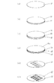
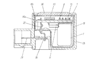
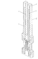
図8は従来の角速度および加速度検出用複合センサの分解斜視図、図9は同角速度および加速度検出用複合センサの側断面図、図10は同角速度および加速度検出用複合センサにおける角速度検出素子の斜視図、図11は同角速度および加速度検出用複合センサの斜視図である。 8 is an exploded perspective view of a conventional sensor for detecting angular velocity and acceleration, FIG. 9 is a side sectional view of the sensor for detecting angular velocity and acceleration, and FIG. 10 is a perspective view of an angular velocity detecting element in the sensor for detecting angular velocity and acceleration. 11 and 11 are perspective views of the composite sensor for detecting angular velocity and acceleration.
図8〜図11において、1は角速度検出手段で、この角速度検出手段1は、図10に示している互いに結晶軸の異なる単結晶の水晶製の薄板を貼り合わせた音叉からなる振動体2と、この振動体2を収納するケース3と、このケース3の上面に設けた開口部(図示せず)を閉塞する蓋4とにより構成されている。また、角速度検出手段1を構成する振動体2の表面および裏面には駆動電極5を設け、かつ外側面および内側面には検出電極6を設けている。そしてまた、前記角速度検出手段1を構成するケース3は振動体2を内側に収納するとともに、上面に開口部(図示せず)を設けている。さらに、前記角速度検出手段1を構成する蓋4は、図8に示すように、上面から下面にわたって貫通するように電源端子7、角速度出力端子8およびGND端子9を設けており、そして前記電源端子7およびGND端子9の一端を前記振動体2における駆動電極5と電気的に接続している。また、前記蓋4に設けた角速度出力端子8は一端を振動体2における検出電極6に電気的に接続している。
8 to 11,
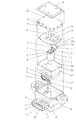
11は加速度信号処理IC(図示せず)を内蔵した加速度検出手段で、この加速度検出手段11は内部に可動電極板(図示せず)および固定電極板(図示せず)を設けるとともに、この可動電極板(図示せず)および固定電極板(図示せず)と一端が電気的に接続された電源端子12、X軸加速度出力端子13a、Y軸加速度出力端子13bおよびGND端子14を外方へ突出するように設けている。15は回路基板で、この回路基板15は前記角速度検出手段1を下面に固着するとともに、上面から下面にわたって多数の端子挿通孔16を設けており、そして、この端子挿通孔16に角速度検出手段1における電源端子7、角速度出力端子8およびGND端子9を挿通している。また、前記回路基板15は下面に加速度検出手段11を固着するとともに、上面にAGC回路(図示せず)を設けた電子部品からなる角速度信号処理IC17を設け、そしてこの角速度信号処理IC17に角速度検出手段1における電源端子7、角速度出力端子8、GND端子9および加速度検出手段11における電源端子12、X軸加速度出力端子13a、Y軸加速度出力端子13bおよびGND端子14を電気的に接続している。
18は金属製のシールドケースで、このシールドケース18は収納部18aと、この収納部18aの開口部18bを閉塞する蓋18cとにより構成されている。また、このシールドケース18は内側に回路基板15、角速度検出手段1および加速度検出手段11を収納するとともに、電源中継端子19、GND中継端子20、角速度中継端子21、X軸加速度中継端子22およびY軸加速度中継端子23を内部から外部に貫通するように設けている。そしてまた、このシールドケース18は電源中継端子19の一端を角速度検出手段1における電源端子7および加速度検出手段11における電源端子12に電気的に接続するとともに、GND中継端子20の一端を角速度検出手段1におけるGND端子9および加速度検出手段11におけるGND端子14に電気的に接続し、そして角速度中継端子21の一端を角速度検出手段1における角速度出力端子8に電気的に接続し、さらに、X軸加速度中継端子22の一端を加速度検出手段11におけるX軸加速度出力端子13aに電気的に接続するとともに、Y軸加速度中継端子23の一端を加速度検出手段11におけるY軸加速度出力端子13bに電気的に接続している。そしてまた、前記シールドケース18の蓋18cには垂直部分18dに切込みを入れることにより構成された弾性突起からなる付勢手段24を設け、そしてこの付勢手段24により、蓋18cをシールドケース18における開口部18bの外側面に弾着させて、収納部18aを蓋18cと同電位にしている。
25は有底筒状に構成された樹脂製の保護ケースで、この保護ケース25はシールドケース18を内側に収納するとともに、側面から外方へ突出するようにコネクタ部26を設けており、そしてこのコネクタ部26の内側に電源コネクタ端子27、角速度コネクタ端子28、X軸加速度コネクタ端子29、Y軸加速度コネクタ端子30およびGNDコネクタ端子31の一端を配設し、かつ他端を保護ケース25に埋設している。また、保護ケース25には図11に示すように、底面から外底面にわたって貫通孔32を設けるとともに、電源コネクタ端子27、角速度コネクタ端子28、X軸加速度コネクタ端子29およびY軸加速度コネクタ端子30、GNDコネクタ端子31の他端を保護ケース25に設けた貫通孔32内に位置させている。そして、保護ケース25におけるX軸加速度コネクタ端子29の孔(図示せず)にX軸加速度中継端子22の他端を挿通させて半田35により電気的に接続するとともに、Y軸加速度コネクタ端子30の孔(図示せず)にY軸加速度中継端子23の他端を挿通させて半田35により電気的に接続し、さらに電源コネクタ端子27の孔(図示せず)に電源中継端子19の他端を挿通させて半田35により電気的に接続するとともに、角速度コネクタ端子28の孔(図示せず)に角速度中継端子21の他端を挿通させて半田35により電気的に接続し、GNDコネクタ端子31の孔(図示せず)にGND中継端子20の他端を挿通させて半田35により電気的に接続している。36は樹脂製の保護蓋で、この保護蓋36は保護ケース25の上面に設けた開口部を閉塞しているものである。
25 is a protective case made of resin having a bottomed cylindrical shape. The
以上のように構成され、かつ組み立てられた従来の角速度および加速度検出用複合センサについて、次に、その動作を説明する。 Next, the operation of the conventional composite sensor for angular velocity and acceleration detection constructed and assembled as described above will be described.
まず、外部に設けた電源(図示せず)による直流電圧を、電源コネクタ端子27、電源中継端子19および角速度信号処理IC17により交流電圧に変換し、この交流電圧を電源端子7を介して角速度検出手段1の振動体2の駆動電極5に印加する。また、同様に、駆動電極5をGNDコネクタ端子31、GND中継端子20、GND端子9を介して接地すると、振動体2が屈曲振動する。この状態において、振動体2の長手方向の中心軸周りに角速度ωで角速度検出手段1が回転すると、振動体2にF=2mv×ωのコリオリ力が発生する。このコリオリ力により、検出電極6に発生する電荷からなる出力信号を角速度出力端子8を介して回路基板15における角速度信号処理IC17により出力電圧に変換し、さらに角速度中継端子21および角速度コネクタ端子28を介して、相手側のコンピュータ(図示せず)に入力することにより、角速度を検出するものである。また、同様に、加速度検出手段11における可動電極板(図示せず)および固定電極板(図示せず)に電源コネクタ端子27、電源中継端子19および電源端子7を介して5Vを印加した状態において、加速度検出手段11の平面に水平な方向であるX軸方向およびY軸方向に加速度が加わると、可動電極板(図示せず)が移動することになり、これにより、可動電極板(図示せず)と固定電極板(図示せず)との間に設けたコンデンサの容量が変化する。そして、この容量の変化を加速度検出手段11の内部で、出力電圧に変換し、X軸方向の加速度をX軸加速度出力端子13a、X軸加速度中継端子22およびX軸加速度コネクタ端子29を介して相手側コンピュータ(図示せず)に入力することにより、X軸方向の加速度を検出するものである。また、同様に、Y軸方向の加速度をY軸加速度出力端子13b、Y軸加速度中継端子23およびY軸加速度コネクタ端子30を介して相手側コンピュータ(図示せず)に入力することにより、Y軸方向の加速度を検出するものである。そして、相手側コンピュータ(図示せず)により、車体に加わる角速度、X軸方向の加速度およびY軸方向の加速度を解析することにより、車体の挙動を分析するものである。
First, a DC voltage from an external power source (not shown) is converted into an AC voltage by the
なお、この出願の発明に関する先行技術文献情報としては、例えば、特許文献1が知られている。
As prior art document information relating to the invention of this application, for example,
しかしながら、上記従来の構成においては、回路基板15に角速度検出手段1における電源端子7、角速度出力端子8およびGND端子9がリジッドに固定されているため、角速度検出手段1における振動体2の屈曲振動が回路基板15を介して加速度検出手段11に直接に伝達されることとなり、これにより、加速度検出手段11における可動電極板が移動すると、加速度が生じていないにも関わらず、加速度出力信号を検出してしまうという課題を有していた。
However, in the above-described conventional configuration, the
本発明は、上記従来の課題を解決するもので、角速度検出手段における振動体の屈曲振動が加速度検出手段に直接に伝達されることにより、加速度が生じていないにも関わらず、加速度出力信号を検出してしまうということのない信頼性の向上した角速度および加速度検出用複合センサを提供することを目的とするものである。 The present invention solves the above-described conventional problem, and the acceleration output signal is obtained by transmitting the flexural vibration of the vibrating body in the angular velocity detecting means directly to the acceleration detecting means, even though no acceleration is generated. It is an object of the present invention to provide a composite sensor for detecting angular velocity and acceleration with improved reliability that will not be detected.
上記目的を達成するために、本発明は以下の構成を有するものである。 In order to achieve the above object, the present invention has the following configuration.
本発明の請求項1に記載の発明は、角速度を検出する振動子と、加速度を検出する加速度検出素子と、前記振動子から発生する角速度出力信号を処理するとともに加速度検出素子から発生する加速度出力信号を処理するICと、前記振動子、加速度検出素子およびICを収納するとともに、内側面に端子電極を設け、さらに外底面に電源電極、GND電極および出力電極を設けたケースとを備え、前記振動子を防振端子を介してケースに固定するとともに、加速度検出素子をケースにリジッドに固定するようにしたもので、この構成によれば、振動子を防振端子を介してケースに固定するとともに、加速度検出素子をケースにリジッドに固定するようにしたため、振動子の屈曲振動が防振端子により減衰することとなり、これにより、振動子の振動が加速度検出素子に伝わりづらいから、加速度が生じていないにも関わらず、加速度出力信号を検出してしまうことがなくなるとともに、加速度検出素子をケースにリジッドに固定しているため、精度良く加速度を検出することができるという作用効果を有するものである。 According to a first aspect of the present invention, an oscillator for detecting angular velocity, an acceleration detecting element for detecting acceleration, an angular velocity output signal generated from the vibrator and an acceleration output generated from the acceleration detecting element An IC for processing a signal, and a case in which the vibrator, the acceleration detection element, and the IC are housed, a terminal electrode is provided on an inner surface, and a power electrode, a GND electrode, and an output electrode are provided on an outer bottom surface, The vibrator is fixed to the case via the vibration isolating terminal and the acceleration detecting element is rigidly fixed to the case. According to this configuration, the vibrator is fixed to the case via the vibration isolating terminal. At the same time, since the acceleration detecting element is rigidly fixed to the case, the flexural vibration of the vibrator is attenuated by the anti-vibration terminal. Since it is difficult for vibration to be transmitted to the acceleration detection element, the acceleration output signal is not detected even though no acceleration is generated, and the acceleration detection element is rigidly fixed to the case, so the acceleration can be accurately performed. It has the effect that can be detected.
本発明の角速度および加速度検出用複合センサは、角速度を検出する振動子と、加速度を検出する加速度検出素子と、前記振動子から発生する角速度出力信号を処理するとともに加速度検出素子から発生する加速度出力信号を処理するICと、前記振動子、加速度検出素子およびICを収納するとともに、内側面に端子電極を設け、さらに外底面に電源電極、GND電極および出力電極を設けたケースとを備え、前記振動子を防振端子を介してケースに固定するとともに、加速度検出素子をケースにリジッドに固定するようにしたもので、この構成によれば、振動子を防振端子を介してケースに固定するとともに、加速度検出素子をケースにリジッドに固定するようにしたため、振動子の屈曲振動が防振端子により減衰することとなり、これにより、振動子の振動が加速度検出素子に伝わりづらいから、加速度が生じていないにも関わらず、加速度出力信号を検出してしまうことがなくなるとともに、加速度検出素子をケースにリジッドに固定しているため、精度良く加速度を検出することが可能な角速度および加速度検出用複合センサを提供することができるという効果を有するものである。 The composite sensor for detecting angular velocity and acceleration according to the present invention includes an oscillator for detecting angular velocity, an acceleration detecting element for detecting acceleration, an angular velocity output signal generated from the vibrator, and an acceleration output generated from the acceleration detecting element. An IC for processing a signal, and a case in which the vibrator, the acceleration detection element, and the IC are housed, a terminal electrode is provided on an inner surface, and a power electrode, a GND electrode, and an output electrode are provided on an outer bottom surface, The vibrator is fixed to the case via the vibration isolating terminal and the acceleration detecting element is rigidly fixed to the case. According to this configuration, the vibrator is fixed to the case via the vibration isolating terminal. At the same time, since the acceleration detecting element is rigidly fixed to the case, the flexural vibration of the vibrator is attenuated by the anti-vibration terminal. Since the vibration of the vibrator is difficult to be transmitted to the acceleration detection element, the acceleration output signal is not detected even though no acceleration is generated, and the acceleration detection element is rigidly fixed to the case. Therefore, it has an effect that it is possible to provide a composite sensor for detecting angular velocity and acceleration capable of accurately detecting acceleration.
以下、本発明の一実施の形態における角速度および加速度検出用複合センサについて、図面を参照しながら説明する。 Hereinafter, an angular velocity and acceleration detection composite sensor according to an embodiment of the present invention will be described with reference to the drawings.
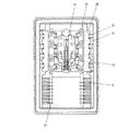
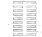
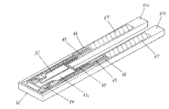
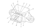
図1は本発明の一実施の形態における角速度および加速度検出用複合センサの分解斜視図、図2は同角速度および加速度検出用複合センサの上蓋を外した状態を示す上面図、図3は同角速度および加速度検出用複合センサの下面図、図4は同角速度および加速度検出用複合センサにおける振動子の斜視図、図5は同角速度および加速度検出用複合センサにおける振動子の側断面図、図6は同角速度および加速度検出用複合センサにおける載置部材に振動子および端子を固定した状態を示す斜視図である。 FIG. 1 is an exploded perspective view of a composite sensor for detecting angular velocity and acceleration according to an embodiment of the present invention, FIG. 2 is a top view showing a state in which the upper cover of the composite sensor for detecting angular velocity and acceleration is removed, and FIG. FIG. 4 is a perspective view of a vibrator in the composite sensor for detecting angular velocity and acceleration, FIG. 5 is a side sectional view of the vibrator in the composite sensor for detecting angular velocity and acceleration, and FIG. It is a perspective view which shows the state which fixed the vibrator | oscillator and the terminal to the mounting member in the composite sensor for the same angular velocity and acceleration detection.
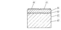
図1〜図6において、61は音叉形状の振動子で、この振動子61は図4に示すように、第1の腕部61a、第2の腕部61bおよび第1の腕部61aと第2の腕部61bの一端を接続する支持部61cとにより構成されている。また、振動子61は図5に示すように、Siからなる基材62の上面の全面にわたってPtとTiの合金薄膜からなる共通GND電極63を設け、さらにこの共通GND電極63の上面にPZT薄膜からなる圧電層64を設けている。そしてまた、音叉形状の振動子61は、図4に示すように、上面の略中央の内側に位置して、圧電層64の上面に一対の第1の駆動電極65を設けるとともに、略中央の外側に位置して圧電層64の上面に一対の第2の駆動電極66を設けている。また、この振動子61は、上面の先端側に位置して、圧電層64の上面に一対の検出電極67を設けるとともに、第1の駆動電極65より根元側に位置して、圧電層64の上面にモニター電極68を設けている。そしてまた、振動子61における支持部61cの表面に位置して、圧電層64の表面にGND電極69を設けている。
1 to 6,
70はセラミックからなるケースで、このケース70は内底面および内側面から外底面にわたってセラミックと配線用導体の層構造からなり、配線パターン(図示せず)を有する多層回路基板72を設けている。また、前記ケース70の側壁73の内側面に設けた段差部74に端子電極75を設けるとともに、外底面に電源電極76、GND電極77および出力電極78を設けており、前記端子電極75と、電源電極76、GND電極77および出力電極78とを、配線パターン(図示せず)により電気的に接続している。そして、また、ケース70における側壁73の上面にコバールからなる金属枠79を設けている。80は樹脂製の載置部材で、この載置部材80は前記振動子61における支持部61cを支持するとともに、前記ケース70における端子電極75と一端を電気的に接続された8つの端子81により周囲から支持されている。そして、前記端子81は、各々Y軸方向延出部82、Z軸方向延出部83およびX軸方向延出部84により構成されており、8つの端子81のうち、外側に配置された4つの端子81のX軸方向延出部84は表方向に延出され、一方、内側に配置された4つの端子81のX軸方向延出部84は裏方向に延出されている。すなわち、載置部材80の重心と8つの端子81をあわせた重心とが、互いに略一致するように構成されている。
すなわち、8つの端子81のX軸方向延出部を表裏互いに逆方向に延出するようにすることにより、複数の端子81の重心と載置部材80の重心とが互いに略一致するようにしたため、Y軸方向およびZ軸方向に角速度が加わった際に、複数の端子の重心移動により、振動子61が上方向もしくは下方向に移動することがなくなり、振動子61から発生する信号が安定するという作用効果を有するものである。
That is, by extending the X-axis direction extending portions of the eight
そしてまた、前記振動子61における第1の駆動電極65、第2の駆動電極66、検出電極67およびGND電極69は端子81とワイヤー線85により電気的に接続されている。86は樹脂製の補強部材で、この補強部材86は前記端子81とケース70における端子電極75との接続箇所を覆うように設けることにより、端子81をケース70に埋設している。
In addition, the
そして、ケース70における端子電極75に接続する端子81をケース70に埋設するようにしたため、端子電極75と端子81との接続が強固となり、これにより、強い振動が角速度センサに加わったとしても、端子電極75と端子81との電気的な接続を確保することができるという作用効果を有するものである。
And since the terminal 81 connected to the
87は加速度センサ素子で、この加速度センサ素子87は前記ケース70の内底面に設けられるとともに、端子電極75とワイヤー線85により電気的に接続されている。88はICで、このIC88は前記ケース70の内底面に加速度センサ素子87と並設されるとともに、振動子61からの出力信号および加速度センサ素子87からの出力信号を処理している。89はコバールからなる上蓋で、この上蓋89は前記ケース70の開口部を閉塞している。
以上のように構成された本発明の一実施の形態における角速度および加速度検出用複合センサについて、次に、その組立方法を説明する。 Next, a method for assembling the composite sensor for detecting angular velocity and acceleration according to the embodiment of the present invention configured as described above will be described.
まず、予め準備した図7(a)に示すSiからなる基材62の上面に図7(b)に示すように、PtとTiの合金薄膜からなる共通GND電極63を蒸着により形成し、その後、図7(c)に示すように、共通GND電極63の上面にPZT薄膜からなる圧電層64を蒸着により形成する。
First, as shown in FIG. 7B, a
次に、図7(d)に示すように、圧電層64の上面にTiとAuの合金薄膜からなる形成途上電極65aを蒸着により形成し、その後、図7(e)に示すように、所定の形状になるように、共通GND電極63、圧電層64および形成途上電極65aの不要な箇所を除去し、圧電層64の上面に第1の駆動電極65、第2の駆動電極66、検出電極67、モニター電極68およびGND電極69を形成する。
Next, as shown in FIG. 7D, a forming
次に、共通GND電極63側に電圧を印加するとともに、第1の駆動電極65、第2の駆動電極66、検出電極67、モニター電極68およびGND電極69を接地することにより、圧電層64を分極する。
Next, a voltage is applied to the
次に、基材62における不要な箇所を除去することにより、図7(f)に示すように、個片の振動子61を形成する。
Next, by removing unnecessary portions in the
次に、予め準備したセラミックからなる絶縁体(図示せず)と配線用導体(図示せず)からなる多層回路基板72の上面の外周にわたって、セラミックからなる側壁73および段差部74を形成した後、この段差部74の上面に、Auからなる端子電極75を形成し、さらに、側壁73の上面にコバールからなる金属枠79を固着する。
Next, after the
次に、多層回路基板72の下面にAgからなる電源電極76、GND電極77および出力電極78を形成する。
Next, a
次に、IC88をケース70における多層回路基板72の上面に実装し、その後、このIC88と多層回路基板72とを電気的に接続する。
Next, the
次に、前記ケース70における多層回路基板72の上面に、IC88と並設するように、加速度センサ素子87を実装した後、加速度センサ素子87とケース70における端子電極75とをアルミニウムからなるワイヤー線85を介してワイヤーボンディングにより電気的に接続する。
Next, after mounting the
次に、予め、8つの端子81を載置部材80にインサート成形した後、載置部材80に振動子61における支持部61cの下面を固着し、その後、振動子61の上面に形成された第1の駆動電極65、第2の駆動電極66、検出電極67、モニター電極68およびGND電極69と端子81とをアルミニウムからなるワイヤー線85を介してワイヤーボンディングにより電気的に接続する。
Next, after insert-molding the eight
次に、8つの端子81をケース70における端子電極75に半田付けした後、樹脂製の補強部材86で覆うことにより、端子81をケース70に埋設する。
Next, after the eight
次に、ケース70の開口部に、金属製の上蓋89をシーム溶接により窒素雰囲気中で固着する。
Next, a metal
以上のように構成された本発明の一実施の形態における角速度センサについて、次に、その動作を説明する。 Next, the operation of the angular velocity sensor according to the embodiment of the present invention configured as described above will be described.
まず、音叉型の振動子61における第1の腕部61aおよび第1の腕部61aに設けた第1の駆動電極65に正電圧を印加するとともに、第2の駆動電極66に負電圧を印加すると、第1の駆動電極65の下側に位置する圧電層64が伸びるとともに、第2の駆動電極66の下側に位置する圧電層64が縮むため、振動子61における第1の腕部61aおよび第2の腕部61bが外側に向かって開かれる。
First, a positive voltage is applied to the
次に、音叉型の振動子61における第1の腕部61aおよび第1の腕部61aに設けた第1の駆動電極65に負電圧を印加するとともに、第2の駆動電極66に正電圧を印加すると、第1の駆動電極65の下側に位置する圧電層64が縮むとともに、第2の駆動電極66の下側に位置する圧電層64が伸びるため、振動子61における第1の腕部61aおよび第2の腕部61bが内側に向かって閉じられる。すなわち、音叉型の振動子61における第1の駆動電極65および第2の駆動電極66に交流電圧を印加すると、振動子61における第1の腕部61aおよび第2の腕部61bは面内方向の固有振動数で速度Vの屈曲運動をする。そして、振動子61の屈曲運動はモニター電極68から発生する出力信号が一定になるように、第1の駆動電極65および第2の駆動電極66に印加する電圧を調整することにより、屈曲振動の振幅を制御している。
Next, a negative voltage is applied to the
そしてまた、振動子61における第1の腕部61aおよび第2の腕部61bが固有振動数で屈曲運動している状態において、振動子61が長手方向の中心軸(検知軸)周りに角速度ωで回転すると、振動子61における第1の腕部61aおよび第2の腕部61bのアームにF=2mV×ωのコリオリ力が発生する。このコリオリ力により、検出電極67の下側に位置する圧電層64に発生する電荷からなる出力信号を検出電極67、ワイヤー線85、端子電極75、ケース70における配線パターン(図示せず)を介してIC88に入力し、波形処理をした後、ケース70における出力電極78から外部に角速度の出力信号として出力するものである。
In addition, in the state where the
そしてまた、角速度および加速度検出用複合センサに加速度が加わると、加速度に応じて、加速度検出素子87に出力信号が発生する。その出力信号を多層回路基板72、端子電極75、ワイヤー線85を介してIC88により信号処理した後、ワイヤー線85を介して端子電極75に入力し、多層回路基板72および出力電極78を介して相手側のコンピューター(図示せず)に入力することにより、加速度を検出するものである。
When an acceleration is applied to the composite sensor for detecting angular velocity and acceleration, an output signal is generated in the
ここで、外部からZ軸方向に約25kHzからなる外乱振動が加わる場合を考える。 Here, consider a case where a disturbance vibration of about 25 kHz is applied in the Z-axis direction from the outside.
端子81にX軸方向延出部84とY軸方向延出部82とにより外部から加わるZ軸方向の振動を減衰させるものである。
The X axis
また、同様に、外部からX軸方向に約25kHzからなる外乱振動が加わる場合には、Y軸方向延出部82とZ軸方向延出部83とにより外部から加わるX軸方向の振動を減衰させるものである。
Similarly, when a disturbance vibration of about 25 kHz is applied in the X-axis direction from the outside, the X-axis direction vibration applied from the outside is attenuated by the Y-
さらに、外部からY軸方向に約25kHzからなる外乱振動が加わる場合には、Z軸方向延出部83とX軸方向延出部84とにより外部から加わるY軸方向の振動を減衰させることができる。
Further, when a disturbance vibration of about 25 kHz is applied from the outside in the Y-axis direction, the Z-
すなわち、本発明の一実施の形態における角速度センサにおいては、端子81にX軸方向延出部84、Y軸方向延出部82およびZ軸方向延出部83を設けたため、X軸方向延出部84とY軸方向延出部82とにより外部から加わるZ軸方向の振動を減衰させるとともに、Y軸方向延出部82とZ軸方向延出部83とにより外部から加わるX軸方向の振動を減衰させ、さらに、Z軸方向延出部83とX軸方向延出部84とにより外部から加わるY軸方向の振動を減衰させることとなり、3軸方向全ての振動を減衰させることができるものである。
That is, in the angular velocity sensor according to the embodiment of the present invention, the terminal 81 is provided with the X-axis
本発明にかかる角速度および加速度検出用複合センサは、角速度検出手段における振動体の屈曲振動が加速度検出手段に直接に伝達されることにより、加速度が生じていないにも関わらず、加速度出力信号を検出してしまうということのない信頼性の向上した角速度および加速度検出用複合センサを提供することができるという効果を有し、特に航空機・車両などの移動体の姿勢制御やナビゲーションシステム等に用いられる角速度および加速度検出用複合センサとして有用である。 The composite sensor for detecting angular velocity and acceleration according to the present invention detects the acceleration output signal even though no acceleration is generated by transmitting the flexural vibration of the vibrating body in the angular velocity detecting means directly to the acceleration detecting means. An angular velocity and acceleration detection composite sensor with improved reliability that can be provided without being lost, and particularly used for attitude control and navigation systems of mobile objects such as aircraft and vehicles It is useful as a composite sensor for acceleration detection.
61 振動子
70 ケース
75 端子電極
76 電源電極
77 GND電極
78 出力電極
81 防振端子
87 加速度検出素子
88 IC
61
Claims (1)
Priority Applications (7)
| Application Number | Priority Date | Filing Date | Title |
|---|---|---|---|
| JP2010207506A JP2012063243A (en) | 2010-09-16 | 2010-09-16 | Composite sensor for angular velocity and acceleration detection |
| PCT/JP2011/000842 WO2011102121A1 (en) | 2010-02-18 | 2011-02-16 | Angular speed sensor and composite sensor for detecting angular speed and acceleration |
| EP11744412.5A EP2538175B1 (en) | 2010-02-18 | 2011-02-16 | Angular speed sensor and composite sensor for detecting angular speed and acceleration |
| EP14200345.8A EP2876411A1 (en) | 2010-02-18 | 2011-02-16 | Angular speed sensor and composite sensor for detecting angular speed |
| US13/579,346 US9091543B2 (en) | 2010-02-18 | 2011-02-16 | Angular speed sensor for detecting angular speed |
| US14/568,953 US20150135830A1 (en) | 2010-02-18 | 2014-12-12 | Angular velocity sensor and angular velocity and acceleration detecting composite sensor |
| US14/745,686 US9448068B2 (en) | 2010-02-18 | 2015-06-22 | Angular velocity sensor |
Applications Claiming Priority (1)
| Application Number | Priority Date | Filing Date | Title |
|---|---|---|---|
| JP2010207506A JP2012063243A (en) | 2010-09-16 | 2010-09-16 | Composite sensor for angular velocity and acceleration detection |
Publications (1)
| Publication Number | Publication Date |
|---|---|
| JP2012063243A true JP2012063243A (en) | 2012-03-29 |
Family
ID=46059107
Family Applications (1)
| Application Number | Title | Priority Date | Filing Date |
|---|---|---|---|
| JP2010207506A Pending JP2012063243A (en) | 2010-02-18 | 2010-09-16 | Composite sensor for angular velocity and acceleration detection |
Country Status (1)
| Country | Link |
|---|---|
| JP (1) | JP2012063243A (en) |
Cited By (2)
| Publication number | Priority date | Publication date | Assignee | Title |
|---|---|---|---|---|
| US9933261B2 (en) | 2015-01-06 | 2018-04-03 | Seiko Epson Corporation | Physical quantity sensor, electronic apparatus and moving object |
| US11372018B2 (en) | 2019-11-29 | 2022-06-28 | Seiko Epson Corporation | Sensor unit, electronic apparatus, and moving object |
Citations (4)
| Publication number | Priority date | Publication date | Assignee | Title |
|---|---|---|---|---|
| JP2005283424A (en) * | 2004-03-30 | 2005-10-13 | Denso Corp | Mechanical quantity sensor device |
| WO2006132277A1 (en) * | 2005-06-09 | 2006-12-14 | Matsushita Electric Industrial Co., Ltd. | Composite sensor |
| JP2007040766A (en) * | 2005-08-01 | 2007-02-15 | Toyota Motor Corp | Sensor unit |
| JP2009080107A (en) * | 2007-09-03 | 2009-04-16 | Panasonic Corp | Inertial force sensor |
-
2010
- 2010-09-16 JP JP2010207506A patent/JP2012063243A/en active Pending
Patent Citations (4)
| Publication number | Priority date | Publication date | Assignee | Title |
|---|---|---|---|---|
| JP2005283424A (en) * | 2004-03-30 | 2005-10-13 | Denso Corp | Mechanical quantity sensor device |
| WO2006132277A1 (en) * | 2005-06-09 | 2006-12-14 | Matsushita Electric Industrial Co., Ltd. | Composite sensor |
| JP2007040766A (en) * | 2005-08-01 | 2007-02-15 | Toyota Motor Corp | Sensor unit |
| JP2009080107A (en) * | 2007-09-03 | 2009-04-16 | Panasonic Corp | Inertial force sensor |
Cited By (2)
| Publication number | Priority date | Publication date | Assignee | Title |
|---|---|---|---|---|
| US9933261B2 (en) | 2015-01-06 | 2018-04-03 | Seiko Epson Corporation | Physical quantity sensor, electronic apparatus and moving object |
| US11372018B2 (en) | 2019-11-29 | 2022-06-28 | Seiko Epson Corporation | Sensor unit, electronic apparatus, and moving object |
Similar Documents
| Publication | Publication Date | Title |
|---|---|---|
| WO2011102121A1 (en) | Angular speed sensor and composite sensor for detecting angular speed and acceleration | |
| JP2003004450A (en) | Composite sensor for angular velocity and acceleration detection | |
| US9453851B2 (en) | Composite sensor for detecting angular velocity and acceleration | |
| JP3807404B2 (en) | Angular velocity sensor | |
| JP4715153B2 (en) | Angular velocity sensor | |
| TW201344156A (en) | Vibrating reed, gyro sensor, electronic apparatus and moving object | |
| JP4449504B2 (en) | Angular velocity sensor | |
| JP2001264070A (en) | Angular velocity sensor | |
| JP2012063243A (en) | Composite sensor for angular velocity and acceleration detection | |
| CN112014588B (en) | Inertial sensor unit mounting method and inertial sensor unit | |
| WO2001020258A1 (en) | Angular velocity sensor | |
| JP2008170295A (en) | Angular velocity sensor | |
| JP5786114B2 (en) | Angular velocity sensor | |
| JP4529286B2 (en) | Angular velocity sensor | |
| JP4304742B2 (en) | Angular velocity sensor | |
| JP2009229071A (en) | Angular velocity sensor | |
| JP2013120179A (en) | Angular velocity sensor | |
| JP2014085263A (en) | Angular velocity sensor | |
| JP2016188809A (en) | Angular velocity sensor | |
| JP2009192459A (en) | Angular velocity sensor | |
| JP2013205155A (en) | Angular velocity sensor | |
| JP2012242230A (en) | Angular velocity sensor | |
| JP2013200240A (en) | Angular velocity sensor and manufacturing method thereof | |
| JP2012108090A (en) | Angular velocity sensor | |
| JP2008232889A (en) | Angular velocity sensor |
Legal Events
| Date | Code | Title | Description |
|---|---|---|---|
| A621 | Written request for application examination |
Free format text: JAPANESE INTERMEDIATE CODE: A621 Effective date: 20130917 |
|
| RD01 | Notification of change of attorney |
Free format text: JAPANESE INTERMEDIATE CODE: A7421 Effective date: 20131015 |
|
| RD01 | Notification of change of attorney |
Free format text: JAPANESE INTERMEDIATE CODE: A7421 Effective date: 20140108 |
|
| RD01 | Notification of change of attorney |
Free format text: JAPANESE INTERMEDIATE CODE: A7421 Effective date: 20140417 |
|
| A131 | Notification of reasons for refusal |
Free format text: JAPANESE INTERMEDIATE CODE: A131 Effective date: 20140701 |
|
| A711 | Notification of change in applicant |
Free format text: JAPANESE INTERMEDIATE CODE: A711 Effective date: 20141007 |
|
| A02 | Decision of refusal |
Free format text: JAPANESE INTERMEDIATE CODE: A02 Effective date: 20141104 |