EP1132626A2 - Hygienic sealing plate for a valve assembly - Google Patents
Hygienic sealing plate for a valve assembly Download PDFInfo
- Publication number
- EP1132626A2 EP1132626A2 EP01102860A EP01102860A EP1132626A2 EP 1132626 A2 EP1132626 A2 EP 1132626A2 EP 01102860 A EP01102860 A EP 01102860A EP 01102860 A EP01102860 A EP 01102860A EP 1132626 A2 EP1132626 A2 EP 1132626A2
- Authority
- EP
- European Patent Office
- Prior art keywords
- sealing plate
- valve
- valve assembly
- multiway
- fluid manifold
- Prior art date
- Legal status (The legal status is an assumption and is not a legal conclusion. Google has not performed a legal analysis and makes no representation as to the accuracy of the status listed.)
- Granted
Links
Images

Classifications
-
- F—MECHANICAL ENGINEERING; LIGHTING; HEATING; WEAPONS; BLASTING
- F15—FLUID-PRESSURE ACTUATORS; HYDRAULICS OR PNEUMATICS IN GENERAL
- F15B—SYSTEMS ACTING BY MEANS OF FLUIDS IN GENERAL; FLUID-PRESSURE ACTUATORS, e.g. SERVOMOTORS; DETAILS OF FLUID-PRESSURE SYSTEMS, NOT OTHERWISE PROVIDED FOR
- F15B13/00—Details of servomotor systems ; Valves for servomotor systems
- F15B13/02—Fluid distribution or supply devices characterised by their adaptation to the control of servomotors
- F15B13/06—Fluid distribution or supply devices characterised by their adaptation to the control of servomotors for use with two or more servomotors
- F15B13/08—Assemblies of units, each for the control of a single servomotor only
- F15B13/0803—Modular units
- F15B13/0821—Attachment or sealing of modular units to each other
-
- F—MECHANICAL ENGINEERING; LIGHTING; HEATING; WEAPONS; BLASTING
- F15—FLUID-PRESSURE ACTUATORS; HYDRAULICS OR PNEUMATICS IN GENERAL
- F15B—SYSTEMS ACTING BY MEANS OF FLUIDS IN GENERAL; FLUID-PRESSURE ACTUATORS, e.g. SERVOMOTORS; DETAILS OF FLUID-PRESSURE SYSTEMS, NOT OTHERWISE PROVIDED FOR
- F15B13/00—Details of servomotor systems ; Valves for servomotor systems
- F15B13/02—Fluid distribution or supply devices characterised by their adaptation to the control of servomotors
- F15B13/06—Fluid distribution or supply devices characterised by their adaptation to the control of servomotors for use with two or more servomotors
- F15B13/08—Assemblies of units, each for the control of a single servomotor only
- F15B13/0803—Modular units
- F15B13/0828—Modular units characterised by sealing means of the modular units
-
- F—MECHANICAL ENGINEERING; LIGHTING; HEATING; WEAPONS; BLASTING
- F15—FLUID-PRESSURE ACTUATORS; HYDRAULICS OR PNEUMATICS IN GENERAL
- F15B—SYSTEMS ACTING BY MEANS OF FLUIDS IN GENERAL; FLUID-PRESSURE ACTUATORS, e.g. SERVOMOTORS; DETAILS OF FLUID-PRESSURE SYSTEMS, NOT OTHERWISE PROVIDED FOR
- F15B13/00—Details of servomotor systems ; Valves for servomotor systems
- F15B13/02—Fluid distribution or supply devices characterised by their adaptation to the control of servomotors
- F15B13/06—Fluid distribution or supply devices characterised by their adaptation to the control of servomotors for use with two or more servomotors
- F15B13/08—Assemblies of units, each for the control of a single servomotor only
- F15B13/0803—Modular units
- F15B13/0832—Modular valves
-
- Y—GENERAL TAGGING OF NEW TECHNOLOGICAL DEVELOPMENTS; GENERAL TAGGING OF CROSS-SECTIONAL TECHNOLOGIES SPANNING OVER SEVERAL SECTIONS OF THE IPC; TECHNICAL SUBJECTS COVERED BY FORMER USPC CROSS-REFERENCE ART COLLECTIONS [XRACs] AND DIGESTS
- Y10—TECHNICAL SUBJECTS COVERED BY FORMER USPC
- Y10T—TECHNICAL SUBJECTS COVERED BY FORMER US CLASSIFICATION
- Y10T137/00—Fluid handling
- Y10T137/8593—Systems
- Y10T137/877—With flow control means for branched passages
- Y10T137/87885—Sectional block structure
Abstract
Description
- The present invention relates to a valve assembly for controlling the fluid flow of a pressure medium. More particularly, the present invention relates to a sealing plate disposed between a multiway valve and a fluid manifold of said valve assembly. Especially, the invention relates to a sealing solution in environments where a high hygienic standard is required.
- A valve assembly according to the preamble of
claim 1 is known from document EP 0 688 958 A1. The disclosed valve assembly comprises a fluid manifold which is provided with a mounting surface. The mounting surface corresponds with a fitting surface of a neighbouring multiway valve in order to connect the fluid ports of both parts for supplying and ejecting the valve assembly. For that reason the fluid manifold comprises a supply channel and one or more ejecting channels, wherein transverse branch channels run from these channels to the mounting surface. On the mounting surface an opening of each branch channel lies opposite an opening of a valve channel. - Furthermore, the valve assembly comprises a sealing element disposed between the mounting surface of the fluid manifold and the fitting surface of the multiway valve. The sealing element surrounds the respective opposite openings of the branch channels and the valve channels. The sealing element is shaped as an elastic sealing plate with a plate-like body covering approximately completely the fitting surface of the fitted multiway valve The sealing element has through holes which correspond with the openings of the branch channels and the valve channels. Each of these trough holes is surrounded by an annular sealing lip formed on the plate-like body of the sealing plate.
- As shown in Fig. 3 of the above-mentioned prior art document the valve arrangement has in its mounted state a small outer gap between the multiway valve and a fluid manifold. Said gap allows dirt and bacteria to get into the area between both mounting parts where the sealing plate is disposed. This is undesirable in environments where a high hygienic standard is required. Because of the gaps it is very difficult to keep the valve arrangement clean enough.
- It is the aim of the present invention to provide a valve arrangement which in contrast to the prior art provides a hygienic connection between a multiway valve and a fluid manifold.
- This aim is obtained in a valve assembly of the above-mentioned kind by using the features of the characterising portion of
claim 1. Thus the invention provides an elastic sealing plate with a special hygienic outer sealing profile formed along the edge on both sides of the sealing plate. - So the present invention avoids an undesired capillary entry of dirt and bacteria into the area between the multiway valve and the fluid manifold. The sealing plate of the invention provides a functional integration through sealing openings of corresponding channels on the one hand and seal the outer gap between said two mounting parts on the other hand without using separate sealing elements.
In one preferred embodiment of the invention the side surface of the fluid manifold is disposed on the same plane as the side surface of the multiway valve. In this case the sealing profile is substantially shaped like a rectangle in the normal state and takes a convex shape in the mounted state in order to avoid sharp edges between the mounting parts. - In another preferred embodiment of the invention the side surface of the fluid manifold is disposed approximately rectangular to the side surface of the multiway valve. In this case the sealing profile is substantially shaped like a concave lip in the mounted state in order to avoid sharp edges between the mounting parts. It can be useful that the concave lip of the sealing profile comprises on its tip a slanting contour for pressing the tip of the lip on the respective surface of one mounting part.
- As a further advantageous development of the invention two concave lips of neighbouring multiway valves form a u-shaped groove between the two multiway valves. The u-shaped groove provides an easy water-run-off when cleaning the valve assembly.
- It is an additional favourable effect of the invention that along the edge of the mounting surface or the fitting surface of the fluid manifold and the multiway valve a fixing section for holding the sealing plate in the desired position is formed respectively. Furthermore, the elastic sealing plate could contain a reinforcing element made by metal or plastics material or another suitable material in order to stabilise the sealing plate.
- The foregoing and other aspects will become apparent from the following detailed description of the invention when considered in conjunction with the enclosed drawings.
- Fig. 1 is a front view together with a cross sectional view A-A of a sealing plate according to a first embodiment of the invention.
- Fig. 2a is a cross sectional view of a valve assembly in the mounted state with the sealing plate of Fig. 1.
- Fig. 2b is a cross sectional view of another valve assembly in the mounted state with the sealing plate of Fig. 1.
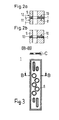
- Fig. 3 is a front view together with a cross sectional view B-B of a sealing plate according to a second embodiment of the invention.
- Fig. 3a is an enlarged view of section C in Fig. 3.
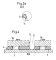
- Fig. 4 is a cross sectional view of a valve assembly with two neighbouring multiway valves in the mounted state with the sealing plate of Fig. 3.
- The
sealing plate 1 shown in Fig. 1 has a plate-like body and through holes 2a to 2e and 3a to 3d for respective openings in the mounting parts. Each through hole 2a to 2e and 3a to 3d is surrounded by anannular sealing lip 4 formed on both sides of theelastic sealing plate 1. In this embodiment the through holes 2a to 2e serve as a sealed connection for channels of the main part of a multiway valve. The through holes 3a to 3d provide a sealed connection for the pilot valve part of the multiway valve. Thesealing plate 1 is also provided with anouter sealing profile 5 formed along theedge 6 on both sides of thesealing plate 1 as shown in the cross sectional view A-A. - The
sealing plate 1 is a part of a valve assembly as shown schematically in Fig. 2a. The valve assembly comprises afluid manifold 7 with amounting surface 8 to which amultiway valve 9 with afitting surface 10 is fitted. Thesealing plate 1 is disposed between themounting surface 8 and thefitting surface 10 covering completely themounting surface 8 and thefitting surface 10. The side surface 11 of thefluid manifold 7 is disposed on the same plane as theside surface 12 of themultiway valve 9. Thesealing profile 5 which is substantially shaped like a rectangle in its normal state takes a convex shape in the mounted state in order to avoid sharp edges and gaps between the mounting parts. In Fig. 2b themultiway valve 9 has along its edge on the fitting surface 10 afixing section 13 for holding thesealing plate 1 in the desired position. - In a second embodiment of the
sealing plate 1 as shown in Fig. 3 and Fig. 3a (enlarged view of section C) the contour of thesealing profile 5 is diagonal shaped. Furthermore, thesealing profile 5 comprises on its tip aslanting contour 14 for pressing the tip of the lip on the surface of one mounting part. - Fig. 4 shows the
sealing profile 5 in the mounted state. In the mounted state thefluid manifold 7 is disposed approximately rectangular to theside surface 12 of themultiway valve 9a or 9b. In this position thesealing profile 5 is shaped like a concave lip in order to avoid sharp edges and gaps between the two mounting parts. Two concave lips of neighbouringmultiway valves 9a and 9b form an u-shapedgroove 15 between the twomultiway valves 9a and 9b. Theu-shaped groove 15 provides an easy water-run-off when cleaning the valve arrangement. - The invention is not limited by the embodiments described above which are presented as examples only but can be modified in various way within the scope of protection defined by the appended patent claims.
Claims (8)
- A valve assembly, comprising a multiway valve (9) with a fitting surface (10) and a fluid manifold (7) with a mounting surface (8), wherein at least one opening of fluid channels inside the fluid manifold (7) lies opposite an opening of a channel of the multiway valve (9) in order to provide a fluid connection between the fluid manifold (7) and the multiway valve (9), and with an elastic sealing plate (1) with a plate-like body and through holes (2a-2e, 3a-3d) for the openings disposed between the mounting surface (8) and the fitting surface (10) and covering approximately completely the fitting surface (10) of the assigned multiway valve (9), wherein each through hole (2a-2e, 3a-3d) is surrounded by an annular sealing lip (4) formed on the elastic sealing plate (1),
characterized in that, the elastic sealing plate (1) is provided with an outer hygienic sealing profile (5) formed along the edge (6) on both sides of the sealing plate (1) in order to avoid a capillary entry of dirt and bacteria into the area between the multiway valve (9) and the fluid manifold (7). - A valve assembly according to claim 1,
characterized in that the side surface (11) of the fluid manifold (7) is disposed on the same plane as the side surface (12) of the multiway valve (9), and the sealing profile (5) is substantially shaped like a rectangle in the normal state which takes a convex shape in the mounted state in order to avoid sharp edges and gaps between the mounting parts. - A valve assembly according to claim 1,
characterized in that the fluid manifold (7) is disposed approximately rectangular to the side surface (12) of the multiway valve (9a, 9b), and the sealing profile (5) is substantially shaped like a concave lip in the mounted state in order to avoid sharp edges and gaps between the mounting parts. - A valve assembly according to claim 3,
characterized in that two concave lips of neighbouring multiway valves (9a, 9b) form a u-shaped groove (15) between the two multiway valves (9a, 9b). - A valve assembly according to claim 3,
characterized in that the lip of the sealing profile (5) comprises on its tip a slanting contour (14) for pressing the tip of the lip on the surface of one mounting part in order to obtain a concave form. - A valve assembly according to claim 1,
characterized in that the elastic sealing plate (1) contains a reinforcing element made of metal or plastics material. - A valve assembly according to claim 1,
characterized in that along the edge of the mounting surface (8) or the fitting surface (10) of the fluid manifold (7) and the multiway valve (12) a fixing section (13) for holding the sealing plate (1) in the desired position is formed respectively. - A valve assembly according to claim 1,
characterized in that the sealing plate (1) is a transfer-moulded part.
Applications Claiming Priority (2)
| Application Number | Priority Date | Filing Date | Title |
|---|---|---|---|
| DE10012067 | 2000-03-06 | ||
| DE10012067A DE10012067C1 (en) | 2000-03-06 | 2000-03-06 | Multi-way valve (hygienic sealing plate) |
Publications (3)
| Publication Number | Publication Date |
|---|---|
| EP1132626A2 true EP1132626A2 (en) | 2001-09-12 |
| EP1132626A3 EP1132626A3 (en) | 2002-08-21 |
| EP1132626B1 EP1132626B1 (en) | 2006-06-07 |
Family
ID=7634471
Family Applications (1)
| Application Number | Title | Priority Date | Filing Date |
|---|---|---|---|
| EP01102860A Expired - Lifetime EP1132626B1 (en) | 2000-03-06 | 2001-02-14 | Hygienic sealing plate for a valve assembly |
Country Status (4)
| Country | Link |
|---|---|
| US (1) | US6488051B2 (en) |
| EP (1) | EP1132626B1 (en) |
| JP (1) | JP2001271931A (en) |
| DE (2) | DE10012067C1 (en) |
Cited By (1)
| Publication number | Priority date | Publication date | Assignee | Title |
|---|---|---|---|---|
| CN110762204A (en) * | 2019-11-05 | 2020-02-07 | 攀钢集团西昌钢钒有限公司 | Porous combined sealing plate |
Families Citing this family (6)
| Publication number | Priority date | Publication date | Assignee | Title |
|---|---|---|---|---|
| DE202004007669U1 (en) * | 2004-05-13 | 2004-09-09 | SBK Siegfried Böhnisch Kunststofftechnik GmbH | Fluid distributor, esp. for water in central heating systems has flat ring seals to cover sealing surfaces between isolation chambers, valve housing, and main duct sections |
| JP4224862B2 (en) * | 2006-10-12 | 2009-02-18 | Smc株式会社 | Valve device |
| KR100989600B1 (en) * | 2010-07-02 | 2010-10-25 | 케이시시정공 주식회사 | The hardy solenoid valve for railway car door |
| US9114788B2 (en) * | 2011-01-27 | 2015-08-25 | Wabtec Holding Corp. | Manifold joint seal |
| EP2746596B1 (en) * | 2012-12-18 | 2017-08-09 | FESTO AG & Co. KG | Valve assembly |
| CN111594629A (en) * | 2020-06-23 | 2020-08-28 | 安徽铜都流体科技股份有限公司 | Double-cutter slurry gate valve for shield machine |
Citations (1)
| Publication number | Priority date | Publication date | Assignee | Title |
|---|---|---|---|---|
| EP0688958A1 (en) | 1994-06-17 | 1995-12-27 | Festo KG | Valve arrangement |
Family Cites Families (11)
| Publication number | Priority date | Publication date | Assignee | Title |
|---|---|---|---|---|
| US3191949A (en) * | 1961-10-26 | 1965-06-29 | Parker Hannifin Corp | Sealed joint and gasket therefor |
| DE8520709U1 (en) * | 1985-07-18 | 1985-10-10 | KSA Dichtsysteme GmbH & Co KG, 7143 Vaihingen | Flat seal |
| DE3637830A1 (en) * | 1986-11-06 | 1988-05-11 | Parker Praedifa Gmbh | SEAL ARRANGEMENT |
| JPH0668336B2 (en) * | 1989-12-20 | 1994-08-31 | 太陽鉄工株式会社 | Solenoid valve manifold |
| DE4143274C2 (en) | 1991-12-27 | 1994-03-10 | Mannesmann Ag | Valve assembly in modular design |
| DE4222637C2 (en) | 1992-07-10 | 1998-12-10 | Festo Ag & Co | Valve arrangement |
| JPH0893942A (en) * | 1994-09-21 | 1996-04-12 | Smc Corp | Seal mechanism for valve assembly |
| JPH09329257A (en) * | 1996-04-09 | 1997-12-22 | Ckd Corp | Seal structure between members |
| US5680883A (en) * | 1996-04-24 | 1997-10-28 | Eaton Corporation | Manifold and valve assembly and filter/gasket therefor |
| DE19621261C2 (en) * | 1996-05-25 | 2001-05-03 | Festo Ag & Co | Sealing arrangement |
| US5893394A (en) * | 1997-06-30 | 1999-04-13 | Ingersoll-Rand Company | Pneumatic valve and method |
-
2000
- 2000-03-06 DE DE10012067A patent/DE10012067C1/en not_active Expired - Fee Related
-
2001
- 2001-02-14 EP EP01102860A patent/EP1132626B1/en not_active Expired - Lifetime
- 2001-02-14 DE DE60120255T patent/DE60120255T2/en not_active Expired - Fee Related
- 2001-02-26 JP JP2001050856A patent/JP2001271931A/en active Pending
- 2001-03-04 US US09/800,458 patent/US6488051B2/en not_active Expired - Fee Related
Patent Citations (1)
| Publication number | Priority date | Publication date | Assignee | Title |
|---|---|---|---|---|
| EP0688958A1 (en) | 1994-06-17 | 1995-12-27 | Festo KG | Valve arrangement |
Cited By (2)
| Publication number | Priority date | Publication date | Assignee | Title |
|---|---|---|---|---|
| CN110762204A (en) * | 2019-11-05 | 2020-02-07 | 攀钢集团西昌钢钒有限公司 | Porous combined sealing plate |
| CN110762204B (en) * | 2019-11-05 | 2022-02-15 | 攀钢集团西昌钢钒有限公司 | Porous combined sealing plate |
Also Published As
| Publication number | Publication date |
|---|---|
| DE60120255T2 (en) | 2007-04-26 |
| EP1132626A3 (en) | 2002-08-21 |
| DE10012067C1 (en) | 2001-09-27 |
| DE60120255D1 (en) | 2006-07-20 |
| US20010047835A1 (en) | 2001-12-06 |
| US6488051B2 (en) | 2002-12-03 |
| JP2001271931A (en) | 2001-10-05 |
| EP1132626B1 (en) | 2006-06-07 |
Similar Documents
| Publication | Publication Date | Title |
|---|---|---|
| EP1435196B1 (en) | An improved irrigation emitter unit | |
| US5636797A (en) | Drip irrigation emitter and flow control unit included therein | |
| EP1629896B1 (en) | Oscillating washer nozzle device with variable angular adjustment | |
| US5086803A (en) | Solenoid valve and manifold assembly | |
| CA2141005A1 (en) | Wire Cutting Insert for Gate Valve | |
| JPH0615186Y2 (en) | Direction switching valve | |
| EP1132626B1 (en) | Hygienic sealing plate for a valve assembly | |
| JP2006207814A (en) | Housing cover | |
| KR100216971B1 (en) | Fixture for fitting pipe joint to chang-over valve | |
| AU4990197A (en) | A filter device for filtering a fluid | |
| US5513674A (en) | Sealing arrangement | |
| CA2331325A1 (en) | Valve gasket formed of composite materials and process | |
| EP1219872A3 (en) | Pressure activated cloth seal | |
| EP1580438A3 (en) | Hydraulic valve section with reduced bore distortion | |
| US20050146210A1 (en) | Hydraulic unit for an anti-slip brake system | |
| US5664789A (en) | Seal construction for use in valve assembly | |
| US6536475B2 (en) | Fluid selector valve | |
| EP0866252A1 (en) | Spool | |
| SE9803873L (en) | Valve manifold device | |
| EP2724061B1 (en) | Valve arrangement | |
| JP3766749B2 (en) | solenoid valve | |
| US20070262537A1 (en) | Method for the Production of a Flat Seal, and Flat Seal | |
| EP1134469A2 (en) | Multiway valve with cap element fixing means | |
| JPH11257509A (en) | Directional control valve | |
| JP2001500819A (en) | Combination device of master cylinder and brake fluid reservoir having snap-in holding configuration |
Legal Events
| Date | Code | Title | Description |
|---|---|---|---|
| PUAI | Public reference made under article 153(3) epc to a published international application that has entered the european phase |
Free format text: ORIGINAL CODE: 0009012 |
|
| AK | Designated contracting states |
Kind code of ref document: A2 Designated state(s): AT BE CH CY DE DK ES FI FR GB GR IE IT LI LU MC NL PT SE TR |
|
| AX | Request for extension of the european patent |
Free format text: AL;LT;LV;MK;RO;SI |
|
| PUAL | Search report despatched |
Free format text: ORIGINAL CODE: 0009013 |
|
| RAP1 | Party data changed (applicant data changed or rights of an application transferred) |
Owner name: BOSCH REXROTH TEKNIK AB |
|
| AK | Designated contracting states |
Kind code of ref document: A3 Designated state(s): AT BE CH CY DE DK ES FI FR GB GR IE IT LI LU MC NL PT SE TR |
|
| AX | Request for extension of the european patent |
Free format text: AL;LT;LV;MK;RO;SI |
|
| RIC1 | Information provided on ipc code assigned before grant |
Free format text: 7F 15B 13/08 A, 7F 15B 13/00 B, 7F 16K 27/00 B, 7F 16J 15/10 B |
|
| 17P | Request for examination filed |
Effective date: 20021125 |
|
| AKX | Designation fees paid |
Designated state(s): FR GB IT SE |
|
| RBV | Designated contracting states (corrected) |
Designated state(s): DE FR GB IT SE |
|
| REG | Reference to a national code |
Ref country code: DE Ref legal event code: 8566 |
|
| 17Q | First examination report despatched |
Effective date: 20040803 |
|
| GRAP | Despatch of communication of intention to grant a patent |
Free format text: ORIGINAL CODE: EPIDOSNIGR1 |
|
| GRAS | Grant fee paid |
Free format text: ORIGINAL CODE: EPIDOSNIGR3 |
|
| GRAA | (expected) grant |
Free format text: ORIGINAL CODE: 0009210 |
|
| AK | Designated contracting states |
Kind code of ref document: B1 Designated state(s): DE FR GB IT SE |
|
| PG25 | Lapsed in a contracting state [announced via postgrant information from national office to epo] |
Ref country code: IT Free format text: LAPSE BECAUSE OF FAILURE TO SUBMIT A TRANSLATION OF THE DESCRIPTION OR TO PAY THE FEE WITHIN THE PRESCRIBED TIME-LIMIT;WARNING: LAPSES OF ITALIAN PATENTS WITH EFFECTIVE DATE BEFORE 2007 MAY HAVE OCCURRED AT ANY TIME BEFORE 2007. THE CORRECT EFFECTIVE DATE MAY BE DIFFERENT FROM THE ONE RECORDED. Effective date: 20060607 |
|
| REG | Reference to a national code |
Ref country code: GB Ref legal event code: FG4D |
|
| REF | Corresponds to: |
Ref document number: 60120255 Country of ref document: DE Date of ref document: 20060720 Kind code of ref document: P |
|
| PG25 | Lapsed in a contracting state [announced via postgrant information from national office to epo] |
Ref country code: SE Free format text: LAPSE BECAUSE OF FAILURE TO SUBMIT A TRANSLATION OF THE DESCRIPTION OR TO PAY THE FEE WITHIN THE PRESCRIBED TIME-LIMIT Effective date: 20060907 |
|
| ET | Fr: translation filed | ||
| PLBE | No opposition filed within time limit |
Free format text: ORIGINAL CODE: 0009261 |
|
| STAA | Information on the status of an ep patent application or granted ep patent |
Free format text: STATUS: NO OPPOSITION FILED WITHIN TIME LIMIT |
|
| 26N | No opposition filed |
Effective date: 20070308 |
|
| PGFP | Annual fee paid to national office [announced via postgrant information from national office to epo] |
Ref country code: DE Payment date: 20090417 Year of fee payment: 9 |
|
| PGFP | Annual fee paid to national office [announced via postgrant information from national office to epo] |
Ref country code: IT Payment date: 20100225 Year of fee payment: 10 Ref country code: FR Payment date: 20100315 Year of fee payment: 10 |
|
| PGFP | Annual fee paid to national office [announced via postgrant information from national office to epo] |
Ref country code: GB Payment date: 20100219 Year of fee payment: 10 |
|
| PG25 | Lapsed in a contracting state [announced via postgrant information from national office to epo] |
Ref country code: DE Free format text: LAPSE BECAUSE OF NON-PAYMENT OF DUE FEES Effective date: 20100901 |
|
| GBPC | Gb: european patent ceased through non-payment of renewal fee |
Effective date: 20110214 |
|
| REG | Reference to a national code |
Ref country code: FR Ref legal event code: ST Effective date: 20111102 |
|
| PG25 | Lapsed in a contracting state [announced via postgrant information from national office to epo] |
Ref country code: IT Free format text: LAPSE BECAUSE OF NON-PAYMENT OF DUE FEES Effective date: 20110214 |
|
| PG25 | Lapsed in a contracting state [announced via postgrant information from national office to epo] |
Ref country code: FR Free format text: LAPSE BECAUSE OF NON-PAYMENT OF DUE FEES Effective date: 20110228 |
|
| PG25 | Lapsed in a contracting state [announced via postgrant information from national office to epo] |
Ref country code: GB Free format text: LAPSE BECAUSE OF NON-PAYMENT OF DUE FEES Effective date: 20110214 |