EP1132325B1 - Verfahren und Vorrichtung zum Aufbringen von Klebestreifen - Google Patents
Verfahren und Vorrichtung zum Aufbringen von KlebestreifenInfo
- Publication number
- EP1132325B1 EP1132325B1 EP01301725A EP01301725A EP1132325B1 EP 1132325 B1 EP1132325 B1 EP 1132325B1 EP 01301725 A EP01301725 A EP 01301725A EP 01301725 A EP01301725 A EP 01301725A EP 1132325 B1 EP1132325 B1 EP 1132325B1
- Authority
- EP
- European Patent Office
- Prior art keywords
- web
- anvil
- tape
- segments
- roll
- Prior art date
- Legal status (The legal status is an assumption and is not a legal conclusion. Google has not performed a legal analysis and makes no representation as to the accuracy of the status listed.)
- Expired - Lifetime
Links
Images


Classifications
-
- B—PERFORMING OPERATIONS; TRANSPORTING
- B65—CONVEYING; PACKING; STORING; HANDLING THIN OR FILAMENTARY MATERIAL
- B65H—HANDLING THIN OR FILAMENTARY MATERIAL, e.g. SHEETS, WEBS, CABLES
- B65H35/00—Delivering articles from cutting or line-perforating machines; Article or web delivery apparatus incorporating cutting or line-perforating devices, e.g. adhesive tape dispensers
- B65H35/0006—Article or web delivery apparatus incorporating cutting or line-perforating devices
- B65H35/006—Article or web delivery apparatus incorporating cutting or line-perforating devices with means for delivering a predetermined length of tape
-
- B—PERFORMING OPERATIONS; TRANSPORTING
- B65—CONVEYING; PACKING; STORING; HANDLING THIN OR FILAMENTARY MATERIAL
- B65H—HANDLING THIN OR FILAMENTARY MATERIAL, e.g. SHEETS, WEBS, CABLES
- B65H35/00—Delivering articles from cutting or line-perforating machines; Article or web delivery apparatus incorporating cutting or line-perforating devices, e.g. adhesive tape dispensers
- B65H35/0006—Article or web delivery apparatus incorporating cutting or line-perforating devices
- B65H35/0013—Article or web delivery apparatus incorporating cutting or line-perforating devices and applying the article or the web by adhesive to a surface
-
- B—PERFORMING OPERATIONS; TRANSPORTING
- B65—CONVEYING; PACKING; STORING; HANDLING THIN OR FILAMENTARY MATERIAL
- B65H—HANDLING THIN OR FILAMENTARY MATERIAL, e.g. SHEETS, WEBS, CABLES
- B65H35/00—Delivering articles from cutting or line-perforating machines; Article or web delivery apparatus incorporating cutting or line-perforating devices, e.g. adhesive tape dispensers
- B65H35/04—Delivering articles from cutting or line-perforating machines; Article or web delivery apparatus incorporating cutting or line-perforating devices, e.g. adhesive tape dispensers from or with transverse cutters or perforators
- B65H35/08—Delivering articles from cutting or line-perforating machines; Article or web delivery apparatus incorporating cutting or line-perforating devices, e.g. adhesive tape dispensers from or with transverse cutters or perforators from or with revolving, e.g. cylinder, cutters or perforators
-
- B—PERFORMING OPERATIONS; TRANSPORTING
- B65—CONVEYING; PACKING; STORING; HANDLING THIN OR FILAMENTARY MATERIAL
- B65H—HANDLING THIN OR FILAMENTARY MATERIAL, e.g. SHEETS, WEBS, CABLES
- B65H39/00—Associating, collating, or gathering articles or webs
- B65H39/14—Associating sheets with webs
-
- B—PERFORMING OPERATIONS; TRANSPORTING
- B65—CONVEYING; PACKING; STORING; HANDLING THIN OR FILAMENTARY MATERIAL
- B65H—HANDLING THIN OR FILAMENTARY MATERIAL, e.g. SHEETS, WEBS, CABLES
- B65H2301/00—Handling processes for sheets or webs
- B65H2301/40—Type of handling process
- B65H2301/43—Gathering; Associating; Assembling
- B65H2301/431—Features with regard to the collection, nature, sequence and/or the making thereof
- B65H2301/4315—Webs
- B65H2301/43151—Webs and ribbons, tapes or strips
-
- B—PERFORMING OPERATIONS; TRANSPORTING
- B65—CONVEYING; PACKING; STORING; HANDLING THIN OR FILAMENTARY MATERIAL
- B65H—HANDLING THIN OR FILAMENTARY MATERIAL, e.g. SHEETS, WEBS, CABLES
- B65H2801/00—Application field
- B65H2801/57—Diaper manufacture
-
- Y—GENERAL TAGGING OF NEW TECHNOLOGICAL DEVELOPMENTS; GENERAL TAGGING OF CROSS-SECTIONAL TECHNOLOGIES SPANNING OVER SEVERAL SECTIONS OF THE IPC; TECHNICAL SUBJECTS COVERED BY FORMER USPC CROSS-REFERENCE ART COLLECTIONS [XRACs] AND DIGESTS
- Y10—TECHNICAL SUBJECTS COVERED BY FORMER USPC
- Y10T—TECHNICAL SUBJECTS COVERED BY FORMER US CLASSIFICATION
- Y10T156/00—Adhesive bonding and miscellaneous chemical manufacture
- Y10T156/10—Methods of surface bonding and/or assembly therefor
- Y10T156/1052—Methods of surface bonding and/or assembly therefor with cutting, punching, tearing or severing
- Y10T156/1062—Prior to assembly
- Y10T156/1067—Continuous longitudinal slitting
- Y10T156/1069—Bonding face to face of laminae cut from single sheet
-
- Y—GENERAL TAGGING OF NEW TECHNOLOGICAL DEVELOPMENTS; GENERAL TAGGING OF CROSS-SECTIONAL TECHNOLOGIES SPANNING OVER SEVERAL SECTIONS OF THE IPC; TECHNICAL SUBJECTS COVERED BY FORMER USPC CROSS-REFERENCE ART COLLECTIONS [XRACs] AND DIGESTS
- Y10—TECHNICAL SUBJECTS COVERED BY FORMER USPC
- Y10T—TECHNICAL SUBJECTS COVERED BY FORMER US CLASSIFICATION
- Y10T156/00—Adhesive bonding and miscellaneous chemical manufacture
- Y10T156/10—Methods of surface bonding and/or assembly therefor
- Y10T156/1052—Methods of surface bonding and/or assembly therefor with cutting, punching, tearing or severing
- Y10T156/1062—Prior to assembly
- Y10T156/1075—Prior to assembly of plural laminae from single stock and assembling to each other or to additional lamina
- Y10T156/1077—Applying plural cut laminae to single face of additional lamina
-
- Y—GENERAL TAGGING OF NEW TECHNOLOGICAL DEVELOPMENTS; GENERAL TAGGING OF CROSS-SECTIONAL TECHNOLOGIES SPANNING OVER SEVERAL SECTIONS OF THE IPC; TECHNICAL SUBJECTS COVERED BY FORMER USPC CROSS-REFERENCE ART COLLECTIONS [XRACs] AND DIGESTS
- Y10—TECHNICAL SUBJECTS COVERED BY FORMER USPC
- Y10T—TECHNICAL SUBJECTS COVERED BY FORMER US CLASSIFICATION
- Y10T156/00—Adhesive bonding and miscellaneous chemical manufacture
- Y10T156/10—Methods of surface bonding and/or assembly therefor
- Y10T156/1052—Methods of surface bonding and/or assembly therefor with cutting, punching, tearing or severing
- Y10T156/1084—Methods of surface bonding and/or assembly therefor with cutting, punching, tearing or severing of continuous or running length bonded web
- Y10T156/1085—One web only
-
- Y—GENERAL TAGGING OF NEW TECHNOLOGICAL DEVELOPMENTS; GENERAL TAGGING OF CROSS-SECTIONAL TECHNOLOGIES SPANNING OVER SEVERAL SECTIONS OF THE IPC; TECHNICAL SUBJECTS COVERED BY FORMER USPC CROSS-REFERENCE ART COLLECTIONS [XRACs] AND DIGESTS
- Y10—TECHNICAL SUBJECTS COVERED BY FORMER USPC
- Y10T—TECHNICAL SUBJECTS COVERED BY FORMER US CLASSIFICATION
- Y10T156/00—Adhesive bonding and miscellaneous chemical manufacture
- Y10T156/10—Methods of surface bonding and/or assembly therefor
- Y10T156/1089—Methods of surface bonding and/or assembly therefor of discrete laminae to single face of additional lamina
- Y10T156/1092—All laminae planar and face to face
- Y10T156/1093—All laminae planar and face to face with covering of discrete laminae with additional lamina
-
- Y—GENERAL TAGGING OF NEW TECHNOLOGICAL DEVELOPMENTS; GENERAL TAGGING OF CROSS-SECTIONAL TECHNOLOGIES SPANNING OVER SEVERAL SECTIONS OF THE IPC; TECHNICAL SUBJECTS COVERED BY FORMER USPC CROSS-REFERENCE ART COLLECTIONS [XRACs] AND DIGESTS
- Y10—TECHNICAL SUBJECTS COVERED BY FORMER USPC
- Y10T—TECHNICAL SUBJECTS COVERED BY FORMER US CLASSIFICATION
- Y10T156/00—Adhesive bonding and miscellaneous chemical manufacture
- Y10T156/10—Methods of surface bonding and/or assembly therefor
- Y10T156/1089—Methods of surface bonding and/or assembly therefor of discrete laminae to single face of additional lamina
- Y10T156/1092—All laminae planar and face to face
- Y10T156/1097—Lamina is running length web
-
- Y—GENERAL TAGGING OF NEW TECHNOLOGICAL DEVELOPMENTS; GENERAL TAGGING OF CROSS-SECTIONAL TECHNOLOGIES SPANNING OVER SEVERAL SECTIONS OF THE IPC; TECHNICAL SUBJECTS COVERED BY FORMER USPC CROSS-REFERENCE ART COLLECTIONS [XRACs] AND DIGESTS
- Y10—TECHNICAL SUBJECTS COVERED BY FORMER USPC
- Y10T—TECHNICAL SUBJECTS COVERED BY FORMER US CLASSIFICATION
- Y10T156/00—Adhesive bonding and miscellaneous chemical manufacture
- Y10T156/12—Surface bonding means and/or assembly means with cutting, punching, piercing, severing or tearing
- Y10T156/1317—Means feeding plural workpieces to be joined
- Y10T156/1322—Severing before bonding or assembling of parts
- Y10T156/133—Delivering cut part to indefinite or running length web
-
- Y—GENERAL TAGGING OF NEW TECHNOLOGICAL DEVELOPMENTS; GENERAL TAGGING OF CROSS-SECTIONAL TECHNOLOGIES SPANNING OVER SEVERAL SECTIONS OF THE IPC; TECHNICAL SUBJECTS COVERED BY FORMER USPC CROSS-REFERENCE ART COLLECTIONS [XRACs] AND DIGESTS
- Y10—TECHNICAL SUBJECTS COVERED BY FORMER USPC
- Y10T—TECHNICAL SUBJECTS COVERED BY FORMER US CLASSIFICATION
- Y10T156/00—Adhesive bonding and miscellaneous chemical manufacture
- Y10T156/12—Surface bonding means and/or assembly means with cutting, punching, piercing, severing or tearing
- Y10T156/1317—Means feeding plural workpieces to be joined
- Y10T156/1322—Severing before bonding or assembling of parts
- Y10T156/1339—Delivering cut part in sequence to serially conveyed articles
-
- Y—GENERAL TAGGING OF NEW TECHNOLOGICAL DEVELOPMENTS; GENERAL TAGGING OF CROSS-SECTIONAL TECHNOLOGIES SPANNING OVER SEVERAL SECTIONS OF THE IPC; TECHNICAL SUBJECTS COVERED BY FORMER USPC CROSS-REFERENCE ART COLLECTIONS [XRACs] AND DIGESTS
- Y10—TECHNICAL SUBJECTS COVERED BY FORMER USPC
- Y10T—TECHNICAL SUBJECTS COVERED BY FORMER US CLASSIFICATION
- Y10T156/00—Adhesive bonding and miscellaneous chemical manufacture
- Y10T156/12—Surface bonding means and/or assembly means with cutting, punching, piercing, severing or tearing
- Y10T156/1317—Means feeding plural workpieces to be joined
- Y10T156/1343—Cutting indefinite length web after assembly with discrete article
-
- Y—GENERAL TAGGING OF NEW TECHNOLOGICAL DEVELOPMENTS; GENERAL TAGGING OF CROSS-SECTIONAL TECHNOLOGIES SPANNING OVER SEVERAL SECTIONS OF THE IPC; TECHNICAL SUBJECTS COVERED BY FORMER USPC CROSS-REFERENCE ART COLLECTIONS [XRACs] AND DIGESTS
- Y10—TECHNICAL SUBJECTS COVERED BY FORMER USPC
- Y10T—TECHNICAL SUBJECTS COVERED BY FORMER US CLASSIFICATION
- Y10T156/00—Adhesive bonding and miscellaneous chemical manufacture
- Y10T156/17—Surface bonding means and/or assemblymeans with work feeding or handling means
- Y10T156/1702—For plural parts or plural areas of single part
- Y10T156/1712—Indefinite or running length work
- Y10T156/1734—Means bringing articles into association with web
-
- Y—GENERAL TAGGING OF NEW TECHNOLOGICAL DEVELOPMENTS; GENERAL TAGGING OF CROSS-SECTIONAL TECHNOLOGIES SPANNING OVER SEVERAL SECTIONS OF THE IPC; TECHNICAL SUBJECTS COVERED BY FORMER USPC CROSS-REFERENCE ART COLLECTIONS [XRACs] AND DIGESTS
- Y10—TECHNICAL SUBJECTS COVERED BY FORMER USPC
- Y10T—TECHNICAL SUBJECTS COVERED BY FORMER US CLASSIFICATION
- Y10T156/00—Adhesive bonding and miscellaneous chemical manufacture
- Y10T156/17—Surface bonding means and/or assemblymeans with work feeding or handling means
- Y10T156/1702—For plural parts or plural areas of single part
- Y10T156/1744—Means bringing discrete articles into assembled relationship
- Y10T156/1751—At least three articles
- Y10T156/1754—At least two applied side by side to common base
Definitions
- the present invention relates to processes and apparatus for applying tabs to traveling webs.
- the invention has particular applicability to the manufacture of disposable diapers.
- Window-knife applicators are comprised of: one or more rotating heads, each made up of a knife edge and a vacuum plate; a more or less stationary knife, which is configured with a hole (window); and a tape transfer mechanism.
- the rotating heads are mechanically configured so as to eliminate head rotation relative to the stationary knife.
- Each head is passed, once per cycle, across the face of the stationary window knife, through which the infeeding tape is passed.
- the rotating knife shears the extended length of tape against the sharp inner edge of the hole (window), after which the severed segment is held by the vacuum plate.
- the rotating head with the segment of tape held in place by the vacuum plate, continues through its rotation to a point, usually 90 degrees later, where it contacts the traveling web, which is pressed against the exposed adhesive of the tape segment.
- This contact usually against some backing device, effects a transfer of the tape tab from the vacuum plate to the traveling web, which then carries the tape tab downstream.
- Window-knife applicators have a few shortcomings, among which are: the difficulty in feeding tape webs with little axial stiffness; the tendency of the infeeding tape to adhere to the window knife-edge; and for exposed adhesive to contaminate the surfaces of the window knife.
- some degree of interference between the cutting edges is necessary between the moving and stationary knife faces, so to minimize impact, precision in manufacturing must be maintained and provision must be made for a degree of resiliency. While applicators of this type have been tested to speeds of 1000 cuts per minute, the maximum practical speed capability of current designs is approximately 750 cuts per minute.
- Slip-and-cut applicators are typically comprised of (a) a cylindrical rotating vacuum anvil, (b) a rotating knife roll and, (c) a transfer device.
- a tape web is fed at a relatively low speed along the vacuum face of the rotating anvil, which is moving at a relatively higher surface speed and upon which the tape web is allowed to "slip".
- a knife-edge mounted on the rotating knife roll, cuts a segment of tape from the tape web against the anvil face. This knife-edge is preferably moving at a surface velocity similar to that of the anvil's circumference. Once cut, the tape tab is held by vacuum drawn through holes on the anvil's face as it is carried at the anvil's speed downstream to the transfer point where the tape segment is transferred to the traveling web.
- a common problem with slip-and-cut applicators lies in the tendency to accumulate various contaminants on their anvil surfaces. This is most frequently seen in the form of the release compounds found on the non-adhesive side of tape, which is shipped on pre-wound rolls. Where die-cut tapes are fed onto the surfaces of slip-and-cut applicators, it is common to also see an accumulation of adhesive contamination, as the adhesive has been exposed at the tape edges by the die-cutting process. The difference in speed between the tape web and the anvil tends to "wipe" adhesive from the tape web. Contamination of the anvil, whether by release compounds or by fugitive adhesive, interferes with the regularity of slip occurring between the tape and the anvil, causing registration and cut accuracy problems. Frequent cleaning is necessary to maintain any level of productivity.
- Continual improvements and competitive pressures have incrementally increased the operational speeds of disposable diaper converters. As speeds increased, the mechanical integrity and operational capabilities of the applicators had to be improved accordingly. As a further complication, the complexity of the tape tabs being attached has also increased. Consumer product manufacturers are offering tapes which are die-cut to complex profiles and which may be constructed of materials incompatible with existing applicators. For instance, a proposed tape tab may be a die-profiled elastic textile, instead of a typical straight-cut stiff-paper and plastic type used in the past. Consequently, a manufacturer may find itself with a window-knife applicator, which cannot feed a tape web with too little axial stiffness. It could also find itself with a slip-and-cut applicator, which cannot successfully apply die-cut tape segments.
- EP-A-0358382 describe an apparatus comprising a tape-apply wheel having an internal vacuum to hold the tape thereon. Tape is carried on the wheel and cut into pieces and then applied to a web.
- US 4,576,600 describes a machine for forming diaper fasteners and for attaching them to a diaper web at constant intervals along the web.
- the machine comprise a large diameter roll whose interior may be coupled to a vacuum source.
- a diaper fastening tape is carried on this roll and is cut into strips by cutting anvils.
- the strips are carried on the roll to alignment with a rotary pressing device where they are pressed onto the margin of a diaper web.
- tape segments are cut and carried at a very low tape web infeed speed.
- problems with transferring a slow-moving segment to a fast-moving web are overcome. Additionally, die cutting of tape segments to any number of practical shapes is possible, thereby avoiding difficulties associated with prior attempts to do so using previous applicator technology, which required multiple steps to accomplish the same task.
- the invention provides the additional benefit of quiet operation compared to prior art equipment, which uses high speed cutting faces and suffers from the effects of the very high energy levels seen at the point of contact. Generally, these energies, and the sounds that they generate, increase in proportion to the square of the velocity.
- the present invention benefits from the relatively low speed of the cutting faces and exhibits extremely low noise levels. In fact, the underlying noise of the mechanical drive systems and the traveling web equipment contribute to make the cutting noise level nearly unnoticeable.
- the present invention provides a simplified process wherein a rotary knife or die, with one or more cutting edges, turns against and in coordination with a corresponding vacuum anvil cylinder.
- An infeeding tape web is fed along the surface of the anvil, which is rotating at a surface velocity equal to or only somewhat greater than that of the tape web.
- segments of tape are parted but not significantly displaced upon the anvil surface. The segments continue downstream on the anvil surface, held securely by forces induced by a vacuum source directed to one or more holes provided for each segment in the anvil surface.
- the segments are transferred to a transfer roll.
- the traveling web to which the segments are to be attached is brought into close proximity with the transfer roll and its tape segments.
- a mechanically operated device which may be as simple as a protuberance on a rotating cylinder, presses the target zone of the traveling web against the exposed adhesive of the tape segment as it is presented on the transfer roll surface.
- the protuberance preferably has a surface velocity substantially identical to that of the traveling web. Given the extremely low moment of inertia of the tape segment and the aggressive adhesion provided between its exposed adhesive and the compatible surface of the traveling web, each successive segment is successfully transferred to the traveling web, accelerating almost instantly to the speed of the traveling web.
- a key aspect of this invention lies in the method and apparatus used to effect the transfer of the tape segments from the transfer roll to the traveling web.
- a vacuum commutation system is configured to remove or reduce the level of vacuum used to hold each tape segment to the transfer roll surface just before the point of transfer.
- the materials and finishes selected for the transfer roll and the transfer protuberance provide a situation in which the coefficient of friction between the protuberance and the traveling web is relatively high, while the coefficient of friction between the tape segment and the transfer roll is relatively low.
- the highly aggressive nature of the bond between the adhesive side of the tape segment and the target surface of the traveling web ensures that there is virtually no slippage between the two.
- This method is extremely effective in that 25 mm tape segments can be accurately transferred at 800 mm spacing to webs traveling at 300 meters per minute or more. This is a web-to-tape velocity ratio of 32:1. Tape to tape positional accuracy has been found to be extremely precise, with standard deviations of less than 1 mm when applied at a 800 mm spacing. Additionally, a speed capability of more than 2,400 tapes per minute is achievable, easily exceeding the limits of any previously known disposable paper product manufacturing process.
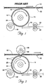
- FIG. 1 a diagrammatic illustration of a prior art process for applying tabs to webs in a diaper making process.
- Web 10 is a composite material used in formation of diapers which is generally formed of various layers of material such as plastic back sheets, absorbent pads and nonwoven topsheets.
- a series of tape segments 12 are applied to web 10.
- a rotatable vacuum anvil 14 is used to supply the tabs 12 which have an outwardly facing adhesive coated surface used to adhere the tabs 12 to web 10.
- Anvil 14 has internally reduced air pressure or vacuum, and a plurality of openings 24 are provided through its surface to enable suction of the tabs segments 12 against the anvil surface 14.
- a web of the tape tab forming material 16 is fed by rollers 20 and 22 against the anvil surface 14 where it is cut into segments by a rotary knife 18.
- anvil 14 is rotated at a speed such that its outer perimeter, and thus the tabs 12 carried thereby, are moving at a speed approximately equal to that of web 10. This causes a great deal of slippage to occur between the anvil 14 and the lower speed infeeding web 16.
- the web 16 is fed to the anvil 24 at a speed such that the web speed of web 16 approximately equals the speed at which the outer periphery of anvil 14 is traveling. If desired, the anvil 14 may rotate at a slightly higher speed than the linear speed of the web 16.
- the blades 34 of a rotary cutter 32 are also traveling at a peripheral speed equal to that of anvil 14.
- a series of tabs 12 are carried on the outer surface of anvil 14. Tabs 12 are held in place by vacuum provided within the interior of anvil 14.
- the adhesive-coated surface of web 16 is facing outwardly while a non-tacky or uncoated surface engages the exterior anvil 14.
- a web 10 of diaper material is caused to travel in a path slightly displaced from the outer surface of rotating anvil 14, but in close proximity thereto.
- a rotating wheel 38 which rotates at a peripheral velocity equal to the lineal velocity of web 10, which, in turn, is substantially greater than the peripheral velocity of anvil 14.
- Anvil 14 may travel at a peripheral velocity either equal to or somewhat greater than the velocity of web 10. In practice, the peripheral velocity of anvil 14 should not be greater than about 5 times the velocity of web 10.
- Wheel 38 as seen in Figure 2, has a protrusion 36 which extends along its width.
- the rotational speed of roller 38 is selected so that the protrusion 36 engages web 10 and displaces it into contact with each successive adhesive-coated tab 12.
- the slight displacement of web 10 causes it to come into contact with the tab segment 12 which, then, is instantly adhered to the higher speed traveling web 10.
- the coefficient of friction between the uncoated side of tab 12 and the metal surface of anvil 14 is low so that the aggressive adhesion between tab 12 and web 10 together with the extremely low moment of inertia of tape tab segment 12 facilitates successful transfer of the tabs 12 to the web 10, the tabs 12 accelerating almost instantly to the higher speed of web 10.
- a vacuum commutation is provided to remove or substantially reduce the level of vacuum used to hold tape segments 12 to the anvil surface 14 just before the point of transfer.
- an interior arcuate plenum 25 is situated within anvil 14 in order to provide vacuum only along the portion of anvil 14 which engages web 16 up to a location just short of the transfer point. Thus, the portion of the anvil 14 which does not engage web 16 or tabs 12 is not provided with vacuum.
- protrusions 36 can simply be in the form of a lobe on the cylindrical surface as low as 0.030 inch in height, but may, if desired, be of a much greater height.
- FIG. 3 there is seen an arrangement of the apparatus generally more suited for commercial operation.
- web 10 is travelling to the left and adhesive-backed tape 16 is fed over a roller 121 onto anvil/drum 114.
- Tape web 16 is cut into individual tape tabs by a rotary cutter 132.
- the tape tab segments 12 travel to the top of drum 114 as viewed in Figure 3, the web 10 is intermittently impacted by lobes 136 located on opposite sides of rotatable wheel 138.
- the apparatus is driven by a motor or power supply 130 through various mechanical drive connections generally shown by dotted or phantom lines in Figure 4.
- a second laterally displaced anvil 115 receives another tape web 16 which is cut into tab segments 12 by blades 135 on a rotary cutter 133.
- a pair of lobes or protrusions 139 on a rotatable wheel 137 cause the web 10 to pick up each successive tab segment 12 from the anvil 115 just as in the case of the other anvil 114.
- tape tabs 12 are applied to each lateral edge of a web which is subsequently formed into a diaper product.
- These tape tabs 12 may have ends provided with hook and loop fasteners or other fastening means selected for use in connection with the diaper product.
- the rotatable anvils 114 and 115 are rotatably driven by a shaft 140.
- rotary cutters 132 and 133 are mounted on another shaft 142 while the rotatable disks 138 and 137 are mounted on another shaft 144.
- FIGs 5 and 6 there is seen still an apparatus particularly suited to manufacture of baby diapers having tape tabs thereon.
- the rotatable anvil 70 as viewed in Figure 5, is similar to anvil 14 previously described in detail.
- a rotary cutter 72 is provided with cutting blades just as in the case of cutter 32.
- a rotatable bar 74 is provided with ends 76 and 78 that serve to push a traveling web against a succession of tabs 12 carried by the anvil 70.
- the apparatus and operation of the device shown in Figures 5 and 6 is similar to that previously described.
- a second anvil 71 is engaged by a second rotary cutter 73 to cut a second series of tabs for the lateral side of the diapers opposite that engaged by anvil 70.
- a second rotary bar 75 is provided with lobes 77 and 79 which serve in the same fashion as lobes 76 and 78 of rotary bar 74.
- the anvils 70 and 71 are rotatably mounted on a shaft 80 and rotatable bars 74 and 75 are rotatably mounted on a shaft 82 while cutters 72 and 73 are mounted on shafts 81 and 83, respectively. All of these devices may be driven, as shown, by a supply of power from a rotating shaft 84 driven by a power supply common to other components of the production line.
- the arrangement of drive belts, etc., as shown for purposes of illustration, such components of the production line would routinely be designed by engineers skilled in the art.
- FIG 7 there is shown, for purposes of clarity, a simplified device illustrating the application of tabs 52 and 54 which have free ends extending laterally from opposite sides of a diaper-forming web 50. These free ends of tabs 52 and 54 may be provided with loops on one side of the diaper-forming material and hooks on the opposite side to form hook and loop fasteners on the diapers commonly referred to as Velcro®. In other cases, the tabs on at least one side may be coated with a pressure sensitive adhesive protected until use by a release layer.
- an adhesive-coated tape web 61 is fed over a roller 64 onto an anvil 60 similar to anvil 14 previously described.
- a similar anvil 62 engages a second adhesive-coated web.
- These webs may have adhesive coated on one-half of their width and a hook or loop-type fastener provided on the opposite half of the width in order to form the laterally extending tabs 52 and 54.
- These webs are cut by blades 56 of rotary cutters 58 and blades 57 of a second rotary cutter 59, respectively.
- both of the cutters 58 and 59 are driven by a rotatable shaft 55.
- anvils 60 and 62 are driven by a central shaft 63.
- Rotatable disks 66 and 68 provided with protrusions 65 and 67 serve to deflect the edges of the web 50 toward the respective anvils 60 and 62 in order to simultaneously pick up the tabs 54 and 52 on opposite sides of the web 50, as shown.
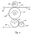
- FIG. 8 An embodiment of the invention is illustrated in Figure 8.
- a diaper-forming web 210 is intermittently coated with adhesive deposits 204 along the edge of the web 210.
- a tab-forming web 202 is fed over a hollow vacuum anvil 216 and cut thereagainst into a series of tabs 208 by blades 219 of a rotary cutter 218.
- An intermediate transfer roll 214 also provided with internal vacuum is used to transport the tabs 208 into close proximity with the bottom of web 210.
- a traveling drum 238 having lobes 236 is traveling at a speed such that a lobe 236 contacts the web 210 just as an adhesive-coated area 204 is aligned with one of the tabs 208. Displacement caused by action of the lobe 236 against the web 210 causes the each tab 208 to become adhered to one of the adhesive coated areas 204.
- the operation of the device of Figure 8 is similar to that previously heretofore described.
Landscapes
- Absorbent Articles And Supports Therefor (AREA)
- Application Of Or Painting With Fluid Materials (AREA)
Claims (14)
- Verfahren zum Anbringen von Klebestreifen an einer laufenden Bahn (210) mit folgenden Verfahrensschritten
Bereitstellen einer drehbaren Anpresswalze (216) mit einer Umfangsfläche und eines Drehschneiders (218) zum Schneiden von Abschnitten an der Anpresswalze aus einer kontinuierlich zugeführten ersten Bahn (202) aus die Klebestreifen bildendem Material, wobei die Anpresswalze innen an vermindertem Druck angeschlossen ist und auf ihrer Umfangsfläche Durchbrechungen aufweist,
Zuführen der ersten Bahn zu der Anpresswalze (216) mit einer ersten Geschwindigkeit während der Drehung der Anpresswalze (216) mit einer Umfangsgeschwindigkeit, die größer als oder gleich der ersten Geschwindigkeit ist,
Schneiden einer Folge von Klebestreifen (208) gegen die Umfangsfläche der Anpresswalze (216) und Überführen der Klebestreifen (208) in der Folge mit der rotierenden Umfangsfläche, indem der verminderte Luftdruck zum Festhalten der Klebestreifen (208) auf der Umfangsfläche eingesetzt wird,
gekennzeichnet durch folgende Verfahrensschritte:Bereitstellen einer dazwischen geschalteten Übergabewalze (214), die innen an vermindertem Druck angeschlossen ist, und Antreiben der Übergabewalze mit einer Umfangsgeschwindigkeit, die größer als oder gleich der Umfangsgeschwindigkeit der Anpresswalze (216) ist, nahe bei der Anpresswalze (216), wobei jeder Klebestreifen in der Folge von der Anpresswalze (216) an die Übergabewalze (214) übergeben wird,Zuführen der laufenden Bahn (210) nahe bei, jedoch mit Abstand zu der Übergabewalze (214) mit einer wesentlich größeren Geschwindigkeit als die erste Geschwindigkeit,intermittierendes Andrücken der laufenden Bahn (210) in Richtung auf die Übergabewalze (214) und unter Kontakt zu jedem Klebesteifen (208) in der Folge, wodurch die Klebestreifen an der Bahn (210) ankleben. - Verfahren nach Anspruch 1, dadurch gekennzeichnet, dass ein Verschiebeelement (236) relativ zu der laufenden Bahn vorgesehen ist und dass die Bahn intermittierend in Richtung auf die Übergabewalze durch Bewegen des Verschiebeelements (236) in Richtung auf die Bahn ausgelenkt wird.
- Verfahren nach Anspruch 2, dadurch gekennzeichnet, dass das Verschiebeelement (236) als ein Vorsprung auf einer Drehtrommel (238) ausgebildet ist.
- Verfahren nach Anspruch 3, dadurch gekennzeichnet, dass die Drehtrommel (238) mit einer solchen Geschwindigkeit angetrieben wird, dass der Vorsprung (236) die Bahn (210) an jeden aufeinander folgenden Klebesteifen (208) andrückt.
- Verfahren nach Anspruch 3, dadurch gekennzeichnet, dass die Drehtrommel (238) mehrere Vorsprünge (236) aufweist und dass die Drehtrommel mit einer solchen Geschwindigkeit angetrieben wird, dass die laufende Bahn (210) mit jedem Klebestreifen in der Folge in Kontakt kommt.
- Verfahren nach Anspruch 1, dadurch gekennzeichnet, dass die Bahn (210) zur Bildung von Wegwerfwindeln aus einem zusammengesetzten Material besteht.
- Verfahren nach Anspruch 1, dadurch gekennzeichnet, dass die Klebestreifen (208) als vorgeformte Elemente ausgebildet sind und aufeinander folgend im Strom der Anpresswalze (216) zugeführt werden.
- Verfahren nach Anspruch 1, dadurch gekennzeichnet, dass die erste Bahn (202) auf der der Anpresswalze (216) abgekehrten Seite eine Klebebeschichtung aufweist.
- Verfahren nach Anspruch 1, dadurch gekennzeichnet, dass die Klebestreifen (208) mit einem Drehschneider (218) geschnitten werden.
- Vorrichtung zum Anbringen von Klebestreifen an einer laufenden Bahn (210), mit
einem Vorsprung (236) auf einer Drehtrommel (238) zum Andrücken eines ausgewählten Bereichs der laufenden Bahn (210) gegen den nach außen weisenden Kleber der aus der ersten Bahn (202) geschnittenen Klebestreifen (208), wobei jeder Klebestreifen in der Folge an der laufenden Bahn (210) anhaftet, dadurch gekennzeichnet, dass die Vorrichtung
eine Anpresswalze (216), gegen die die Klebestreifen (208) aus der ersten Bahn (202) geschnitten werden,
eine Übergabewalze (214) mit einer von Durchbrechungen für den Anschluss eines Vakuums durchsetzten Umfangsfläche,
Mittel zum Ausbilden eines Vakuums innen in der Übergabewalze,
Mittel zum Zuführen eines Stroms aufeinander folgender und mit Kleber versehener
Klebestreifen zu der Übergabewalze (214), wobei der Kleber relativ zum Zentrum der Übergabewalze nach außen zeigt, und
Mittel zum Fördern der laufenden Bahn (210) benachbart zu der Übergabewalze (214)
aufweist. - Vorrichtung nach Anspruch 10, dadurch gekennzeichnet, dass die Mittel (216) zum Zuführen des Stroms aufeinander folgender und mit Kleber versehener Klebestreifen zu der Übergabewalze (214) eine hohle Anpresswalze aufweisen, und dass die Vorrichtung zusätzlich einen Drehschneider (218) zum Schneiden der Klebestreifen aus einer der Anpresswalze (216) zugeführten Bahn aufweist.
- Vorrichtung zum Anbringen von Klebestreifen an einer laufenden Bahn (210), mit
einer Anpresswalze (216), die auf einer Umfangsfläche Durchbrechungen für die Einwirkung eines Vakuums und Mittel zum Aufbau eines Vakuums in dieser Anpresswalze (216) aufweist,
Mittel zum Zuführen einer kontinuierlich laufenden Bahn aus mit Kleber versehenen Klebestreifen zu der Anpresswalze, wobei der Kleber relativ zum Zentrum der Anpresswalze nach außen zeigt,
einem Drehschneider (218), der zum Schneiden der Bahn gegen die Anpresswalze (216) angeordnet ist, wodurch ein aufeinander folgender Strom von Klebestreifen (208) auf der Oberfläche der Anpresswalze (216) entsteht,
dadurch gekennzeichnet, dass die Vorrichtung
eine Übergabewalze (214) mit einer von Durchbrechungen für den Anschluss eines Vakuums durchsetzten Umfangsfläche und Mittel zum Ausbilden eines Vakuums innen in der Übergabewalze (214), wobei die Übergabewalze (214) so angeordnet ist, dass ihre Umfangsfläche sich nahe benachbart zu der Umfangsfläche der ersten Anpresswalze (216) befindet,
Mittel zum Zuführen einer kontinuierlich laufenden Bahn aus mit Kleber versehenen Klebestreifen (208) zu der Übergabewalze, wobei der Kleber relativ zum Zentrum der Übergabewalze nach außen zeigt,
Mittel zum Fördern der laufenden Bahn (210) benachbart zu der Übergabewalze (214),
Mittel (236) zum intermittierenden Andrücken eines ausgewählten Bereichs der
laufenden Bahn (210) unter Kontakt zu der mit Kleber versehenen Oberfläche jedes Klebestreifens (208) auf der Übergabewalze (214)
aufweist. - Vorrichtung nach Anspruch 12, dadurch gekennzeichnet, dass die Mittel zum Andrücken des ausgewählten Bereichs der laufenden Bahn einen Vorsprung (236) auf einer Trommel (238) aufweisen.
- Vorrichtung nach Anspruch 13, dadurch gekennzeichnet, dass die Messerwalze (218) einen rotierenden Stempel aufweist.
Applications Claiming Priority (2)
| Application Number | Priority Date | Filing Date | Title |
|---|---|---|---|
| US521736 | 2000-03-09 | ||
| US09/521,736 US6475325B1 (en) | 2000-03-09 | 2000-03-09 | Tape tab applicator |
Publications (3)
| Publication Number | Publication Date |
|---|---|
| EP1132325A2 EP1132325A2 (de) | 2001-09-12 |
| EP1132325A3 EP1132325A3 (de) | 2004-05-12 |
| EP1132325B1 true EP1132325B1 (de) | 2006-10-04 |
Family
ID=24077921
Family Applications (1)
| Application Number | Title | Priority Date | Filing Date |
|---|---|---|---|
| EP01301725A Expired - Lifetime EP1132325B1 (de) | 2000-03-09 | 2001-02-26 | Verfahren und Vorrichtung zum Aufbringen von Klebestreifen |
Country Status (5)
| Country | Link |
|---|---|
| US (3) | US6475325B1 (de) |
| EP (1) | EP1132325B1 (de) |
| AT (1) | ATE341516T1 (de) |
| CA (1) | CA2337700C (de) |
| DE (1) | DE60123502T2 (de) |
Cited By (24)
| Publication number | Priority date | Publication date | Assignee | Title |
|---|---|---|---|---|
| US7303708B2 (en) | 2004-04-19 | 2007-12-04 | Curt G. Joa, Inc. | Super absorbent distribution system design for homogeneous distribution throughout an absorbent core |
| US7374627B2 (en) | 2004-04-19 | 2008-05-20 | Curt G. Joa, Inc. | Method of producing an ultrasonically bonded lap seam |
| US7398870B2 (en) | 2005-10-05 | 2008-07-15 | Curt G. Joa, Inc | Article transfer and placement apparatus |
| US7452436B2 (en) | 2005-03-09 | 2008-11-18 | Curt G. Joa, Inc. | Transverse tape application method and apparatus |
| US7533709B2 (en) | 2005-05-31 | 2009-05-19 | Curt G. Joa, Inc. | High speed vacuum porting |
| US7537215B2 (en) | 2004-06-15 | 2009-05-26 | Curt G. Joa, Inc. | Method and apparatus for securing stretchable film using vacuum |
| US7618513B2 (en) | 2005-05-31 | 2009-11-17 | Curt G. Joa, Inc. | Web stabilization on a slip and cut applicator |
| US7638014B2 (en) | 2004-05-21 | 2009-12-29 | Curt G. Joa, Inc. | Method of producing a pants-type diaper |
| US7640962B2 (en) | 2004-04-20 | 2010-01-05 | Curt G. Joa, Inc. | Multiple tape application method and apparatus |
| US7703599B2 (en) | 2004-04-19 | 2010-04-27 | Curt G. Joa, Inc. | Method and apparatus for reversing direction of an article |
| US7708849B2 (en) | 2004-04-20 | 2010-05-04 | Curt G. Joa, Inc. | Apparatus and method for cutting elastic strands between layers of carrier webs |
| US7770712B2 (en) | 2006-02-17 | 2010-08-10 | Curt G. Joa, Inc. | Article transfer and placement apparatus with active puck |
| US7780052B2 (en) | 2006-05-18 | 2010-08-24 | Curt G. Joa, Inc. | Trim removal system |
| US7811403B2 (en) | 2005-03-09 | 2010-10-12 | Curt G. Joa, Inc. | Transverse tab application method and apparatus |
| US7861756B2 (en) | 2004-04-20 | 2011-01-04 | Curt G. Joa, Inc. | Staggered cutting knife |
| US7975584B2 (en) | 2007-02-21 | 2011-07-12 | Curt G. Joa, Inc. | Single transfer insert placement method and apparatus |
| US8007484B2 (en) | 2005-04-01 | 2011-08-30 | Curt G. Joa, Inc. | Pants type product and method of making the same |
| US8016972B2 (en) | 2007-05-09 | 2011-09-13 | Curt G. Joa, Inc. | Methods and apparatus for application of nested zero waste ear to traveling web |
| US8172977B2 (en) | 2009-04-06 | 2012-05-08 | Curt G. Joa, Inc. | Methods and apparatus for application of nested zero waste ear to traveling web |
| US8182624B2 (en) | 2008-03-12 | 2012-05-22 | Curt G. Joa, Inc. | Registered stretch laminate and methods for forming a registered stretch laminate |
| CN102471004A (zh) * | 2009-07-31 | 2012-05-23 | 尤妮佳股份有限公司 | 切断转移装置以及切断转移方法 |
| US8398793B2 (en) | 2007-07-20 | 2013-03-19 | Curt G. Joa, Inc. | Apparatus and method for minimizing waste and improving quality and production in web processing operations |
| US8417374B2 (en) | 2004-04-19 | 2013-04-09 | Curt G. Joa, Inc. | Method and apparatus for changing speed or direction of an article |
| US8673098B2 (en) | 2009-10-28 | 2014-03-18 | Curt G. Joa, Inc. | Method and apparatus for stretching segmented stretchable film and application of the segmented film to a moving web |
Families Citing this family (72)
| Publication number | Priority date | Publication date | Assignee | Title |
|---|---|---|---|---|
| US6475325B1 (en) | 2000-03-09 | 2002-11-05 | Curt G. Joa, Inc. | Tape tab applicator |
| ATE380634T1 (de) * | 2000-11-01 | 2007-12-15 | Adalis Corp | Vorschubsystem für bahnförmiges material und vorrichtung zum auftragen von bahnförmigem material |
| US6893528B2 (en) * | 2000-11-01 | 2005-05-17 | Adalis Corporation | Web material advance system for web material applicator |
| JP3602786B2 (ja) * | 2000-11-10 | 2004-12-15 | 東亜機工株式会社 | ラベル貼付方法およびラベル貼付装置 |
| US6915829B2 (en) * | 2002-07-15 | 2005-07-12 | Kimberly-Clark Worldwide, Inc. | Apparatus and method for cutting and placing limp pieces of material |
| US20040007328A1 (en) * | 2002-07-15 | 2004-01-15 | Kimberly-Clark Worldwide, Inc. | Apparatus for cutting and placing limp pieces of material |
| TW584553B (en) | 2002-08-06 | 2004-04-21 | Uni Charm Corp | Method for continuously producing disposable wearing article |
| US7172666B2 (en) | 2002-12-17 | 2007-02-06 | Groves Matthew E | Web material application methods and systems |
| US7293593B2 (en) * | 2004-06-30 | 2007-11-13 | Delta Industrial Services, In. | Island placement technology |
| US8097110B2 (en) * | 2004-06-30 | 2012-01-17 | Delta Industrial Services, Inc. | Island placement technology |
| US9433538B2 (en) | 2006-05-18 | 2016-09-06 | Curt G. Joa, Inc. | Methods and apparatus for application of nested zero waste ear to traveling web and formation of articles using a dual cut slip unit |
| US10456302B2 (en) | 2006-05-18 | 2019-10-29 | Curt G. Joa, Inc. | Methods and apparatus for application of nested zero waste ear to traveling web |
| US9622918B2 (en) | 2006-05-18 | 2017-04-18 | Curt G. Joe, Inc. | Methods and apparatus for application of nested zero waste ear to traveling web |
| US20080060751A1 (en) * | 2006-09-07 | 2008-03-13 | Evan Arrindell | Island label apparatus and method |
| US9944487B2 (en) | 2007-02-21 | 2018-04-17 | Curt G. Joa, Inc. | Single transfer insert placement method and apparatus |
| US9550306B2 (en) | 2007-02-21 | 2017-01-24 | Curt G. Joa, Inc. | Single transfer insert placement and apparatus with cross-direction insert placement control |
| US9387131B2 (en) | 2007-07-20 | 2016-07-12 | Curt G. Joa, Inc. | Apparatus and method for minimizing waste and improving quality and production in web processing operations by automated threading and re-threading of web materials |
| EP2100840A1 (de) * | 2008-03-12 | 2009-09-16 | Philip Morris Products S.A. | Patchapplikator-Vorrichtung und Verfahren |
| US20090294044A1 (en) * | 2008-05-27 | 2009-12-03 | Nathan Alan Gill | Methods and Apparatus for Attaching Elastic Components to Absorbent Articles |
| IT1390737B1 (it) * | 2008-07-04 | 2011-09-23 | Gdm Spa | Macchina per la realizzazione di articoli assorbenti. |
| IT1391867B1 (it) * | 2008-10-30 | 2012-01-27 | Fameccanica Data Spa | Dispositivo e procedimento per realizzare prodotti igienico-sanitari |
| US8007623B2 (en) | 2009-03-27 | 2011-08-30 | Curt G. Joa, Inc. | Apparatus and method for intermittent application of stretchable web to target web |
| EP2238955B1 (de) | 2009-04-06 | 2011-12-28 | Curt G. Joa, Inc. | Verfahren und Vorrichtung zum Anbringen von verschachtelten Windelseitenohren ohne Ausschuss auf eine laufende Bahn |
| US8292863B2 (en) | 2009-10-21 | 2012-10-23 | Donoho Christopher D | Disposable diaper with pouches |
| KR101127660B1 (ko) * | 2009-10-28 | 2012-03-22 | 씨제이제일제당 (주) | 자동 테이핑 장치 및 그 방법 |
| US8460495B2 (en) | 2009-12-30 | 2013-06-11 | Curt G. Joa, Inc. | Method for producing absorbent article with stretch film side panel and application of intermittent discrete components of an absorbent article |
| US9089453B2 (en) | 2009-12-30 | 2015-07-28 | Curt G. Joa, Inc. | Method for producing absorbent article with stretch film side panel and application of intermittent discrete components of an absorbent article |
| JP5409454B2 (ja) | 2010-03-16 | 2014-02-05 | ユニ・チャーム株式会社 | 連続シート状部材の複合体の製造装置 |
| US8663411B2 (en) | 2010-06-07 | 2014-03-04 | Curt G. Joa, Inc. | Apparatus and method for forming a pant-type diaper with refastenable side seams |
| US9603752B2 (en) | 2010-08-05 | 2017-03-28 | Curt G. Joa, Inc. | Apparatus and method for minimizing waste and improving quality and production in web processing operations by automatic cuff defect correction |
| US9902083B2 (en) | 2010-09-30 | 2018-02-27 | The Procter & Gamble Company | Absorbent article substrate trim material removal process and apparatus |
| US8545474B2 (en) | 2010-10-22 | 2013-10-01 | Kimberly-Clark Worldwide, Inc. | Disposable absorbent article with finger tab without compromising stretch |
| US8523836B2 (en) | 2010-10-22 | 2013-09-03 | Kimberly-Clark Worldwide, Inc. | Disposable absorbent article with finger tab |
| US20120157279A1 (en) * | 2010-12-20 | 2012-06-21 | Uwe Schneider | Process and Apparatus for Joining Flexible Components |
| US9566193B2 (en) | 2011-02-25 | 2017-02-14 | Curt G. Joa, Inc. | Methods and apparatus for forming disposable products at high speeds with small machine footprint |
| US8656817B2 (en) | 2011-03-09 | 2014-02-25 | Curt G. Joa | Multi-profile die cutting assembly |
| USD684613S1 (en) | 2011-04-14 | 2013-06-18 | Curt G. Joa, Inc. | Sliding guard structure |
| DK2537495T3 (en) | 2011-06-23 | 2015-08-31 | Joa Curt G Inc | A method and apparatus for using embedded nulspild-ear to the running web |
| US8820380B2 (en) * | 2011-07-21 | 2014-09-02 | Curt G. Joa, Inc. | Differential speed shafted machines and uses therefor, including discontinuous and continuous side by side bonding |
| EP3756631B1 (de) | 2011-10-14 | 2023-12-06 | Curt G. Joa, Inc. | Verfahren und vorrichtungen für die anwendung einer geschachtelten ausschussfreien öse auf eine laufende bahn und ausbilden von artikeln unter verwendung einer doppelschneid-schubeinheit |
| CN104011157B (zh) * | 2011-10-24 | 2015-09-30 | 久光制药株式会社 | 粘接胶带包装袋的制造方法 |
| TWI462380B (zh) | 2011-12-20 | 2014-11-21 | Au Optronics Corp | 電芯及其製造方法 |
| PL2628472T3 (pl) | 2012-02-20 | 2016-07-29 | Joa Curt G Inc | Sposób tworzenia spojeń między oddzielnymi częściami składowymi produktów jednorazowego użytku |
| US9908739B2 (en) | 2012-04-24 | 2018-03-06 | Curt G. Joa, Inc. | Apparatus and method for applying parallel flared elastics to disposable products and disposable products containing parallel flared elastics |
| WO2014004453A1 (en) | 2012-06-29 | 2014-01-03 | The Procter & Gamble Company | System and method for high-speed continuous application of a strip material to a moving sheet-like substrate material |
| US9868606B2 (en) | 2012-06-29 | 2018-01-16 | The Proctor & Gamble Company | Rotary drum apparatus reconfigurable for various size substrates |
| EP2866755B1 (de) | 2012-06-29 | 2016-07-20 | The Procter & Gamble Company | Verfahren und vorrichtung zur befestigung von komponenten an saugfähigen artikeln |
| US9168182B2 (en) | 2012-06-29 | 2015-10-27 | The Procter & Gamble Company | Method and apparatus for attaching elastic components to absorbent articles |
| US9283683B2 (en) | 2013-07-24 | 2016-03-15 | Curt G. Joa, Inc. | Ventilated vacuum commutation structures |
| USD703248S1 (en) | 2013-08-23 | 2014-04-22 | Curt G. Joa, Inc. | Ventilated vacuum commutation structure |
| USD703712S1 (en) | 2013-08-23 | 2014-04-29 | Curt G. Joa, Inc. | Ventilated vacuum commutation structure |
| USD703711S1 (en) | 2013-08-23 | 2014-04-29 | Curt G. Joa, Inc. | Ventilated vacuum communication structure |
| USD704237S1 (en) | 2013-08-23 | 2014-05-06 | Curt G. Joa, Inc. | Ventilated vacuum commutation structure |
| USD703247S1 (en) | 2013-08-23 | 2014-04-22 | Curt G. Joa, Inc. | Ventilated vacuum commutation structure |
| US10308462B2 (en) * | 2013-09-06 | 2019-06-04 | Kimberly-Clark Worldwide, Inc. | Plate for an anvil roll with a reduced-vacuum region for use in a slip and cut system and method of using the same |
| US9609920B2 (en) * | 2013-09-06 | 2017-04-04 | Kimberly-Clark Worldwide, Inc. | Process for modifying a hook profile of a fastening component and a fastening component having hooks with a modified profile |
| US9289329B1 (en) | 2013-12-05 | 2016-03-22 | Curt G. Joa, Inc. | Method for producing pant type diapers |
| CN104972695A (zh) * | 2014-04-02 | 2015-10-14 | 平阳县凯达包装机械厂 | 阀口水泥袋全自动按口机 |
| WO2017019544A1 (en) | 2015-07-24 | 2017-02-02 | Curt G. Joa, Inc. | Vacuum commutation apparatus and methods |
| ITUB20154881A1 (it) * | 2015-10-23 | 2017-04-23 | Gdm Spa | Unita? di applicazione di appendici ad un nastro di supporto. |
| EP3184092B1 (de) * | 2015-12-23 | 2018-03-21 | Ontex BVBA | Vliesstoffeinheit |
| US11279859B2 (en) * | 2016-12-07 | 2022-03-22 | 3M Innovative Properties Company | Methods of passivating adhesives |
| JP6633505B2 (ja) * | 2016-12-22 | 2020-01-22 | ユニ・チャーム株式会社 | 吸収性物品の製造方法 |
| AU2018269186A1 (en) | 2017-05-17 | 2019-11-28 | Berry Global, Inc. | Elastic non-woven lamination method and apparatus |
| DE102017213389B4 (de) * | 2017-08-02 | 2022-07-28 | Heidelberger Druckmaschinen Ag | Rotationsstanze zum Ausstanzen eines Materialstücks aus einem Bedruckstoff |
| CA3091829A1 (en) * | 2018-03-05 | 2019-09-12 | H.B. Fuller Company | Web material application systems and methods |
| US11458690B2 (en) | 2018-08-13 | 2022-10-04 | The Procter & Gamble Company | Method and apparatus for bonding substrates |
| US11737930B2 (en) | 2020-02-27 | 2023-08-29 | Curt G. Joa, Inc. | Configurable single transfer insert placement method and apparatus |
| CN112407482A (zh) * | 2020-11-25 | 2021-02-26 | 宿松九点科技有限公司 | 一种胶带粘接机构 |
| WO2025065730A1 (en) | 2023-09-26 | 2025-04-03 | The Procter & Gamble Company | Refastenable absorbent articles with improved fastening |
| CN117003043B (zh) * | 2023-10-07 | 2023-12-26 | 兴化金孔雀实业发展有限公司 | 一种金属箔切片移送装置 |
| CN119330149B (zh) * | 2024-12-19 | 2025-04-04 | 赢胜节能集团股份有限公司 | 一种具有纠偏功能的丙烯酸胶带异步裁切机 |
Family Cites Families (11)
| Publication number | Priority date | Publication date | Assignee | Title |
|---|---|---|---|---|
| US1393524A (en) * | 1919-07-12 | 1921-10-11 | Endless Belt Corp Inc | Tipping mechanism |
| US2990081A (en) | 1957-09-26 | 1961-06-27 | Minnesota Mining & Mfg | Application of tape to moving objects |
| US3772120A (en) | 1971-11-05 | 1973-11-13 | Joa C Inc | Method for applying attaching tapes to pads |
| US3960646A (en) | 1972-09-18 | 1976-06-01 | The Procter & Gamble Company | Tape tab cutter and applicator |
| US4171239A (en) | 1973-09-24 | 1979-10-16 | Curt G. Joa, Inc. | Method and apparatus for applying adhesive attaching tapes to pads |
| US4576600A (en) * | 1985-03-18 | 1986-03-18 | Curt G. Joa, Inc. | Fasteners for diapers |
| US4701239A (en) | 1985-10-15 | 1987-10-20 | Paper Converting Machine Company | Applicator for applying two or more tapes to a moving web |
| US4795510A (en) | 1987-09-11 | 1989-01-03 | Kimberly-Clark Corporation | Process for applying reinforcing material to a diaper cover material |
| US5021111A (en) * | 1988-08-31 | 1991-06-04 | Minnesota Mining And Manufacturing Company | Apparatus and method for applying heat-sensitive adhesive tape to a web moving at high speed |
| US5482593A (en) * | 1994-04-05 | 1996-01-09 | Minnesota Mining And Manufacturing Company | High speed applicator for adhesive tape |
| US6475325B1 (en) | 2000-03-09 | 2002-11-05 | Curt G. Joa, Inc. | Tape tab applicator |
-
2000
- 2000-03-09 US US09/521,736 patent/US6475325B1/en not_active Expired - Lifetime
-
2001
- 2001-02-21 CA CA002337700A patent/CA2337700C/en not_active Expired - Lifetime
- 2001-02-26 EP EP01301725A patent/EP1132325B1/de not_active Expired - Lifetime
- 2001-02-26 DE DE60123502T patent/DE60123502T2/de not_active Expired - Lifetime
- 2001-02-26 AT AT01301725T patent/ATE341516T1/de not_active IP Right Cessation
- 2001-10-31 US US09/998,464 patent/US6494244B2/en not_active Expired - Lifetime
-
2002
- 2002-02-19 US US10/078,806 patent/US6649010B2/en not_active Expired - Lifetime
Cited By (29)
| Publication number | Priority date | Publication date | Assignee | Title |
|---|---|---|---|---|
| US7303708B2 (en) | 2004-04-19 | 2007-12-04 | Curt G. Joa, Inc. | Super absorbent distribution system design for homogeneous distribution throughout an absorbent core |
| US7374627B2 (en) | 2004-04-19 | 2008-05-20 | Curt G. Joa, Inc. | Method of producing an ultrasonically bonded lap seam |
| US8417374B2 (en) | 2004-04-19 | 2013-04-09 | Curt G. Joa, Inc. | Method and apparatus for changing speed or direction of an article |
| US7703599B2 (en) | 2004-04-19 | 2010-04-27 | Curt G. Joa, Inc. | Method and apparatus for reversing direction of an article |
| US7861756B2 (en) | 2004-04-20 | 2011-01-04 | Curt G. Joa, Inc. | Staggered cutting knife |
| US7708849B2 (en) | 2004-04-20 | 2010-05-04 | Curt G. Joa, Inc. | Apparatus and method for cutting elastic strands between layers of carrier webs |
| US7640962B2 (en) | 2004-04-20 | 2010-01-05 | Curt G. Joa, Inc. | Multiple tape application method and apparatus |
| US7638014B2 (en) | 2004-05-21 | 2009-12-29 | Curt G. Joa, Inc. | Method of producing a pants-type diaper |
| US8557077B2 (en) | 2004-05-21 | 2013-10-15 | Curt G. Joa, Inc. | Method of producing a pants-type diaper |
| US7909956B2 (en) | 2004-05-21 | 2011-03-22 | Curt G. Joa, Inc. | Method of producing a pants-type diaper |
| US7537215B2 (en) | 2004-06-15 | 2009-05-26 | Curt G. Joa, Inc. | Method and apparatus for securing stretchable film using vacuum |
| US7811403B2 (en) | 2005-03-09 | 2010-10-12 | Curt G. Joa, Inc. | Transverse tab application method and apparatus |
| US7452436B2 (en) | 2005-03-09 | 2008-11-18 | Curt G. Joa, Inc. | Transverse tape application method and apparatus |
| US8007484B2 (en) | 2005-04-01 | 2011-08-30 | Curt G. Joa, Inc. | Pants type product and method of making the same |
| US7618513B2 (en) | 2005-05-31 | 2009-11-17 | Curt G. Joa, Inc. | Web stabilization on a slip and cut applicator |
| US7533709B2 (en) | 2005-05-31 | 2009-05-19 | Curt G. Joa, Inc. | High speed vacuum porting |
| US7398870B2 (en) | 2005-10-05 | 2008-07-15 | Curt G. Joa, Inc | Article transfer and placement apparatus |
| US7770712B2 (en) | 2006-02-17 | 2010-08-10 | Curt G. Joa, Inc. | Article transfer and placement apparatus with active puck |
| US7780052B2 (en) | 2006-05-18 | 2010-08-24 | Curt G. Joa, Inc. | Trim removal system |
| US8293056B2 (en) | 2006-05-18 | 2012-10-23 | Curt G. Joa, Inc. | Trim removal system |
| US7975584B2 (en) | 2007-02-21 | 2011-07-12 | Curt G. Joa, Inc. | Single transfer insert placement method and apparatus |
| US8016972B2 (en) | 2007-05-09 | 2011-09-13 | Curt G. Joa, Inc. | Methods and apparatus for application of nested zero waste ear to traveling web |
| US8398793B2 (en) | 2007-07-20 | 2013-03-19 | Curt G. Joa, Inc. | Apparatus and method for minimizing waste and improving quality and production in web processing operations |
| US8182624B2 (en) | 2008-03-12 | 2012-05-22 | Curt G. Joa, Inc. | Registered stretch laminate and methods for forming a registered stretch laminate |
| US8172977B2 (en) | 2009-04-06 | 2012-05-08 | Curt G. Joa, Inc. | Methods and apparatus for application of nested zero waste ear to traveling web |
| CN102471004A (zh) * | 2009-07-31 | 2012-05-23 | 尤妮佳股份有限公司 | 切断转移装置以及切断转移方法 |
| US8714063B2 (en) | 2009-07-31 | 2014-05-06 | Uni-Charm Corporation | Cutting and transferring apparatus and cutting and transferring method |
| CN102471004B (zh) * | 2009-07-31 | 2014-09-03 | 尤妮佳股份有限公司 | 切断转移装置以及切断转移方法 |
| US8673098B2 (en) | 2009-10-28 | 2014-03-18 | Curt G. Joa, Inc. | Method and apparatus for stretching segmented stretchable film and application of the segmented film to a moving web |
Also Published As
| Publication number | Publication date |
|---|---|
| US6649010B2 (en) | 2003-11-18 |
| US6494244B2 (en) | 2002-12-17 |
| EP1132325A2 (de) | 2001-09-12 |
| DE60123502D1 (de) | 2006-11-16 |
| US6475325B1 (en) | 2002-11-05 |
| US20020079045A1 (en) | 2002-06-27 |
| CA2337700A1 (en) | 2001-09-09 |
| DE60123502T2 (de) | 2007-01-11 |
| CA2337700C (en) | 2008-08-12 |
| US20020038686A1 (en) | 2002-04-04 |
| ATE341516T1 (de) | 2006-10-15 |
| EP1132325A3 (de) | 2004-05-12 |
Similar Documents
| Publication | Publication Date | Title |
|---|---|---|
| EP1132325B1 (de) | Verfahren und Vorrichtung zum Aufbringen von Klebestreifen | |
| US7640962B2 (en) | Multiple tape application method and apparatus | |
| EP1868821B1 (de) | Verfahren und vorrichtung zur anbringung eines querlaufenden bandes | |
| EP1990302B1 (de) | Verfahren und Vorrichtung zur Anbringung eines querlaufenden Streifens | |
| US11331223B2 (en) | Methods and apparatuses for assembling elastic laminates with different bond densities for absorbent articles | |
| EP1432577B1 (de) | Vorrichtung und verfahren zum zusammenfügen von absorbierenden kleidungsstücken | |
| EP1994919B1 (de) | Verfahren und Vorrichtung zur Anwendung einer geschachtelten ausschussfreien Öse auf eine laufende Bahn | |
| EP0676352B1 (de) | Klebebandauftraggerät mit hoher Geschwindigkeit | |
| US7533709B2 (en) | High speed vacuum porting | |
| US6524423B1 (en) | Method of transferring a discrete portion of a first web onto a second web | |
| KR20010089307A (ko) | 라벨부착장치와 방법 | |
| AU731306B2 (en) | Adhesive station and labeling machine | |
| EP0566618B1 (de) | Vorrichtung zum anbringen von streifen | |
| WO2025212761A1 (en) | Multi-up slip-cut unit for cutting varying product sizes of absorbent articles and discrete components of a continuous web |
Legal Events
| Date | Code | Title | Description |
|---|---|---|---|
| PUAI | Public reference made under article 153(3) epc to a published international application that has entered the european phase |
Free format text: ORIGINAL CODE: 0009012 |
|
| AK | Designated contracting states |
Kind code of ref document: A2 Designated state(s): AT BE CH CY DE DK ES FI FR GB GR IE IT LI LU MC NL PT SE TR |
|
| AX | Request for extension of the european patent |
Free format text: AL;LT;LV;MK;RO;SI |
|
| REG | Reference to a national code |
Ref country code: DE Ref legal event code: R079 Ref document number: 60123502 Country of ref document: DE Free format text: PREVIOUS MAIN CLASS: B65H0035000000 Ipc: B65H0039140000 |
|
| PUAL | Search report despatched |
Free format text: ORIGINAL CODE: 0009013 |
|
| RIC1 | Information provided on ipc code assigned before grant |
Ipc: 7A 61F 13/58 B Ipc: 7B 65H 35/00 B Ipc: 7B 65H 39/14 A |
|
| AK | Designated contracting states |
Kind code of ref document: A3 Designated state(s): AT BE CH CY DE DK ES FI FR GB GR IE IT LI LU MC NL PT SE TR |
|
| AX | Request for extension of the european patent |
Extension state: AL LT LV MK RO SI |
|
| 17P | Request for examination filed |
Effective date: 20040611 |
|
| AKX | Designation fees paid |
Designated state(s): AT BE CH CY DE DK ES FI FR GB GR IE IT LI LU MC NL PT SE TR |
|
| 17Q | First examination report despatched |
Effective date: 20050307 |
|
| GRAP | Despatch of communication of intention to grant a patent |
Free format text: ORIGINAL CODE: EPIDOSNIGR1 |
|
| RTI1 | Title (correction) |
Free format text: METHOD AND APPARATUS FOR APPLYING TAPE TABS |
|
| GRAS | Grant fee paid |
Free format text: ORIGINAL CODE: EPIDOSNIGR3 |
|
| GRAA | (expected) grant |
Free format text: ORIGINAL CODE: 0009210 |
|
| AK | Designated contracting states |
Kind code of ref document: B1 Designated state(s): AT BE CH CY DE DK ES FI FR GB GR IE IT LI LU MC NL PT SE TR |
|
| PG25 | Lapsed in a contracting state [announced via postgrant information from national office to epo] |
Ref country code: FI Free format text: LAPSE BECAUSE OF FAILURE TO SUBMIT A TRANSLATION OF THE DESCRIPTION OR TO PAY THE FEE WITHIN THE PRESCRIBED TIME-LIMIT Effective date: 20061004 Ref country code: IT Free format text: LAPSE BECAUSE OF FAILURE TO SUBMIT A TRANSLATION OF THE DESCRIPTION OR TO PAY THE FEE WITHIN THE PRESCRIBED TIME-LIMIT;WARNING: LAPSES OF ITALIAN PATENTS WITH EFFECTIVE DATE BEFORE 2007 MAY HAVE OCCURRED AT ANY TIME BEFORE 2007. THE CORRECT EFFECTIVE DATE MAY BE DIFFERENT FROM THE ONE RECORDED. Effective date: 20061004 Ref country code: AT Free format text: LAPSE BECAUSE OF FAILURE TO SUBMIT A TRANSLATION OF THE DESCRIPTION OR TO PAY THE FEE WITHIN THE PRESCRIBED TIME-LIMIT Effective date: 20061004 Ref country code: BE Free format text: LAPSE BECAUSE OF FAILURE TO SUBMIT A TRANSLATION OF THE DESCRIPTION OR TO PAY THE FEE WITHIN THE PRESCRIBED TIME-LIMIT Effective date: 20061004 Ref country code: CH Free format text: LAPSE BECAUSE OF FAILURE TO SUBMIT A TRANSLATION OF THE DESCRIPTION OR TO PAY THE FEE WITHIN THE PRESCRIBED TIME-LIMIT Effective date: 20061004 Ref country code: LI Free format text: LAPSE BECAUSE OF FAILURE TO SUBMIT A TRANSLATION OF THE DESCRIPTION OR TO PAY THE FEE WITHIN THE PRESCRIBED TIME-LIMIT Effective date: 20061004 Ref country code: NL Free format text: LAPSE BECAUSE OF FAILURE TO SUBMIT A TRANSLATION OF THE DESCRIPTION OR TO PAY THE FEE WITHIN THE PRESCRIBED TIME-LIMIT Effective date: 20061004 |
|
| REG | Reference to a national code |
Ref country code: GB Ref legal event code: FG4D |
|
| REG | Reference to a national code |
Ref country code: CH Ref legal event code: EP |
|
| REG | Reference to a national code |
Ref country code: IE Ref legal event code: FG4D |
|
| REF | Corresponds to: |
Ref document number: 60123502 Country of ref document: DE Date of ref document: 20061116 Kind code of ref document: P |
|
| REG | Reference to a national code |
Ref country code: DE Ref legal event code: R096 Ref document number: 60123502 Country of ref document: DE Effective date: 20061116 |
|
| PG25 | Lapsed in a contracting state [announced via postgrant information from national office to epo] |
Ref country code: DK Free format text: LAPSE BECAUSE OF FAILURE TO SUBMIT A TRANSLATION OF THE DESCRIPTION OR TO PAY THE FEE WITHIN THE PRESCRIBED TIME-LIMIT Effective date: 20070104 Ref country code: SE Free format text: LAPSE BECAUSE OF FAILURE TO SUBMIT A TRANSLATION OF THE DESCRIPTION OR TO PAY THE FEE WITHIN THE PRESCRIBED TIME-LIMIT Effective date: 20070104 |
|
| PG25 | Lapsed in a contracting state [announced via postgrant information from national office to epo] |
Ref country code: ES Free format text: LAPSE BECAUSE OF FAILURE TO SUBMIT A TRANSLATION OF THE DESCRIPTION OR TO PAY THE FEE WITHIN THE PRESCRIBED TIME-LIMIT Effective date: 20070115 |
|
| PG25 | Lapsed in a contracting state [announced via postgrant information from national office to epo] |
Ref country code: MC Free format text: LAPSE BECAUSE OF NON-PAYMENT OF DUE FEES Effective date: 20070228 |
|
| PG25 | Lapsed in a contracting state [announced via postgrant information from national office to epo] |
Ref country code: PT Free format text: LAPSE BECAUSE OF FAILURE TO SUBMIT A TRANSLATION OF THE DESCRIPTION OR TO PAY THE FEE WITHIN THE PRESCRIBED TIME-LIMIT Effective date: 20070316 |
|
| NLV1 | Nl: lapsed or annulled due to failure to fulfill the requirements of art. 29p and 29m of the patents act | ||
| REG | Reference to a national code |
Ref country code: CH Ref legal event code: PL |
|
| ET | Fr: translation filed | ||
| PLBE | No opposition filed within time limit |
Free format text: ORIGINAL CODE: 0009261 |
|
| STAA | Information on the status of an ep patent application or granted ep patent |
Free format text: STATUS: NO OPPOSITION FILED WITHIN TIME LIMIT |
|
| 26N | No opposition filed |
Effective date: 20070705 |
|
| GBPC | Gb: european patent ceased through non-payment of renewal fee |
Effective date: 20070226 |
|
| REG | Reference to a national code |
Ref country code: DE Ref legal event code: R097 Ref document number: 60123502 Country of ref document: DE Effective date: 20070705 |
|
| PG25 | Lapsed in a contracting state [announced via postgrant information from national office to epo] |
Ref country code: IE Free format text: LAPSE BECAUSE OF NON-PAYMENT OF DUE FEES Effective date: 20070226 |
|
| PG25 | Lapsed in a contracting state [announced via postgrant information from national office to epo] |
Ref country code: GB Free format text: LAPSE BECAUSE OF NON-PAYMENT OF DUE FEES Effective date: 20070226 Ref country code: GR Free format text: LAPSE BECAUSE OF FAILURE TO SUBMIT A TRANSLATION OF THE DESCRIPTION OR TO PAY THE FEE WITHIN THE PRESCRIBED TIME-LIMIT Effective date: 20070105 |
|
| PG25 | Lapsed in a contracting state [announced via postgrant information from national office to epo] |
Ref country code: CY Free format text: LAPSE BECAUSE OF FAILURE TO SUBMIT A TRANSLATION OF THE DESCRIPTION OR TO PAY THE FEE WITHIN THE PRESCRIBED TIME-LIMIT Effective date: 20061004 Ref country code: LU Free format text: LAPSE BECAUSE OF NON-PAYMENT OF DUE FEES Effective date: 20070226 |
|
| PG25 | Lapsed in a contracting state [announced via postgrant information from national office to epo] |
Ref country code: TR Free format text: LAPSE BECAUSE OF FAILURE TO SUBMIT A TRANSLATION OF THE DESCRIPTION OR TO PAY THE FEE WITHIN THE PRESCRIBED TIME-LIMIT Effective date: 20061004 |
|
| REG | Reference to a national code |
Ref country code: FR Ref legal event code: PLFP Year of fee payment: 16 |
|
| REG | Reference to a national code |
Ref country code: FR Ref legal event code: PLFP Year of fee payment: 17 |
|
| REG | Reference to a national code |
Ref country code: FR Ref legal event code: PLFP Year of fee payment: 18 |
|
| PGFP | Annual fee paid to national office [announced via postgrant information from national office to epo] |
Ref country code: DE Payment date: 20200227 Year of fee payment: 20 Ref country code: IT Payment date: 20200220 Year of fee payment: 20 |
|
| PGFP | Annual fee paid to national office [announced via postgrant information from national office to epo] |
Ref country code: FR Payment date: 20200225 Year of fee payment: 20 |
|
| REG | Reference to a national code |
Ref country code: DE Ref legal event code: R071 Ref document number: 60123502 Country of ref document: DE |
|
| P01 | Opt-out of the competence of the unified patent court (upc) registered |
Effective date: 20230516 |