EP1132268A1 - Reinigungsanlage - Google Patents
Reinigungsanlage Download PDFInfo
- Publication number
- EP1132268A1 EP1132268A1 EP00104999A EP00104999A EP1132268A1 EP 1132268 A1 EP1132268 A1 EP 1132268A1 EP 00104999 A EP00104999 A EP 00104999A EP 00104999 A EP00104999 A EP 00104999A EP 1132268 A1 EP1132268 A1 EP 1132268A1
- Authority
- EP
- European Patent Office
- Prior art keywords
- cleaning system
- volume
- fluid
- elastic element
- outlet device
- Prior art date
- Legal status (The legal status is an assumption and is not a legal conclusion. Google has not performed a legal analysis and makes no representation as to the accuracy of the status listed.)
- Withdrawn
Links
Images

Classifications
-
- B—PERFORMING OPERATIONS; TRANSPORTING
- B60—VEHICLES IN GENERAL
- B60S—SERVICING, CLEANING, REPAIRING, SUPPORTING, LIFTING, OR MANOEUVRING OF VEHICLES, NOT OTHERWISE PROVIDED FOR
- B60S1/00—Cleaning of vehicles
- B60S1/02—Cleaning windscreens, windows or optical devices
- B60S1/46—Cleaning windscreens, windows or optical devices using liquid; Windscreen washers
- B60S1/48—Liquid supply therefor
-
- B—PERFORMING OPERATIONS; TRANSPORTING
- B60—VEHICLES IN GENERAL
- B60S—SERVICING, CLEANING, REPAIRING, SUPPORTING, LIFTING, OR MANOEUVRING OF VEHICLES, NOT OTHERWISE PROVIDED FOR
- B60S1/00—Cleaning of vehicles
- B60S1/02—Cleaning windscreens, windows or optical devices
- B60S1/46—Cleaning windscreens, windows or optical devices using liquid; Windscreen washers
- B60S1/48—Liquid supply therefor
- B60S1/52—Arrangement of nozzles; Liquid spreading means
-
- B—PERFORMING OPERATIONS; TRANSPORTING
- B60—VEHICLES IN GENERAL
- B60S—SERVICING, CLEANING, REPAIRING, SUPPORTING, LIFTING, OR MANOEUVRING OF VEHICLES, NOT OTHERWISE PROVIDED FOR
- B60S1/00—Cleaning of vehicles
- B60S1/02—Cleaning windscreens, windows or optical devices
- B60S1/46—Cleaning windscreens, windows or optical devices using liquid; Windscreen washers
- B60S1/48—Liquid supply therefor
- B60S1/52—Arrangement of nozzles; Liquid spreading means
- B60S1/522—Arrangement of nozzles; Liquid spreading means moving liquid spreading means, e.g. arranged in wiper arms
- B60S1/528—Arrangement of nozzles; Liquid spreading means moving liquid spreading means, e.g. arranged in wiper arms the spreading means being moved between a rest position and a working position
Definitions
- the invention relates to a cleaning system, in particular for headlights, vehicle windows or the like, with those mentioned in the preamble of claim 1 Characteristics.
- Cleaning systems of the generic type are known. They are used in particular to clean the Headlights or the vehicle windows of motor vehicles. For this purpose, they have a hydraulic conveyor on which a fluid to be pumped from a Conveys storage container to an outlet device. The exit device is one assigned cleaning object. All during the promotion of the fluid flowing through elements of the cleaning system are referred to below as fluid-carrying elements designated.
- the outlet device can for example consist of a Cylinder with a hollow piston exist.
- the hollow piston has a head that has a valve nozzle carries over which the fluid is sprayed.
- the Hollow piston can by means of a spring element reversibly stored.
- a disadvantage of the known cleaning systems is that they have little frost resistance. When a freezable fluid solidifies within those necessary to deliver the fluid Elements of the cleaning system there is a volume expansion, the one to increase an internal pressure inside the cleaning system. If not Pressure equalization is more possible, this can be mechanical Strain to deform or even break the lead fluid-carrying elements.
- the invention has for its object a cleaning system of the generic type to create by means of in a simple and inexpensive manner damage to the fluid-carrying elements during solidification of the fluid is prevented.
- this object is achieved by a cleaning system with the features mentioned in claim 1 solved.
- volume-elastic element on an inside of the fluid-carrying elements as one Layer is applied.
- it can volume elastic element tubular inside the fluid-carrying elements or a have other suitable three-dimensional structure. Its variety of forms is limited only by that the promotion of the fluid during normal operation is not prevented or disturbed.
- volume elastic Element made of an elastomer, in particular Rubber, such as ethylene-propylene-diene rubber (EPDM), because of these materials enable inexpensive and simple production.
- Rubber such as ethylene-propylene-diene rubber (EPDM)
- other volume-elastic ones are also Materials can be used, such as gas-filled hollow bodies and deposits with low Dense and high air-filled pores. Essential is just that they are under pressure are compressible.
- FIG. 1 shows a schematic view of a Cleaning system 10, as used in particular for cleaning a headlight used in motor vehicles becomes.
- the cleaning system 10 includes one Conveyor 12, a reservoir 14 and two exit devices 16.
- the exit devices 16 are with the reservoir 14 respectively the conveyor 12 via lines 18 and a T-piece 20 connected.
- they are individual elements that are used during the promotion of a Fluids (fluid-carrying elements) in the cleaning system 10 are flowed through, variable, and it is only to illustrate the solution according to the invention selected the embodiment shown.
- the conveyor 12 can be a pump, in particular a high pressure pump, and the lines 18 and the reservoir 14 can optionally from a elastic plastic.
- the outlet device 16 is the Cleaning system 10 in a schematic sectional view shown. It consists of a cylinder 24 with an inlet opening 22 and a hollow piston 26.
- the hollow piston 26 has a head 28, the one Valve nozzle 30 carries through which the fluid in the form of a Spray cone 32 can be sprayed.
- the hollow piston 26 protrudes from an opening 34 of the cylinder 24 and has an outside diameter that is smaller than the inside diameter of the cylinder 24. On this Way forms between the outside 36 of the Hollow piston 26 and the inside 38 of the cylinder 24 a cavity 40 out.
- a spring element 42 housed that at a ledge 44 of the hollow piston 26 and on the cylinder 24.
- the cylinder 24 has 38 on its inside a projection 46.
- the hollow piston 26 in a rest in such a way applied a force that it bears against the projection 46 of the cylinder 24. Is the fluid in through the conveyor 12 Directed the exit device 16, so this enters the cylinder through the inlet opening 22 24 a. Since the hollow piston 26 respectively the valve nozzle 30 is a taper, it comes to an increase in pressure as a result of which the hollow piston 26 is pressed outwards and the spring element 42 is excited. After switching off the conveyor 12 takes place by means of the spring element 42 a reversing movement of the hollow piston 26 to this again bears against the projection 46.
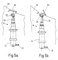
- the exit device 16 is for reasons the aerodynamics integrated in a bumper 58, the hollow piston 26 in a rest position below a flap 60 is arranged (Figure 5a).
- Figure 5a When freezing of the fluid due to a volume expansion, which are mainly directed axially onto the hollow piston 26 is gradually extended, so that the flap 60 opens ( Figure 5b). Since the open Flap 60 is often visually disturbing for a driver is felt and this, if necessary, the Flap 60, and thus the hollow piston 26, it can damage the outlet device 16 come.
- An alternative, somewhat reset Positioning of the exit device 16 is often not possible due to the lack of installation space.
- FIG. 3 shows an example schematic sectional view through such a modified Hollow piston 26.
- the volume-elastic element 50 is here as a layer 56 on an inside 48 of the hollow piston 26 applied.
- a The thickness of the layer 56 can be chosen variably.
- FIG. 4 shows a further alternative embodiment of the volume-elastic element 50.
- the volume-elastic element 50 inside of the hollow piston 26, for example along a Central axis 54.
- the shown embodiments of Figures 3 and 4 only two possible forms of the volume-elastic element 50.
- other three-dimensional are also conceivable Structures provided they have a trouble-free Allow fluid flow.
- volume-elastic elements 50 in principle in each fluid-carrying element 12, 14, 16 of the cleaning system 10 integrate.
- Such a specific embodiment can be in the individual Elements 12, 14, 16 realized differently are, that is, according to the technical requirements can this as a layer and / or three-dimensional Structure.
- the volume-elastic element 50 is, for example made of an elastomer, especially rubber, such as ethylene propylene diene rubber (EPDM).
- EPDM ethylene propylene diene rubber
- This Elastomer is characterized by its resistance to Isopropyl alcohol, ethanol, glycol, surfactants or the like, which are common additives for a washing liquid in cleaning systems 10 be used.
- Isopropyl alcohol, ethanol, glycol, surfactants or the like which are common additives for a washing liquid in cleaning systems 10 be used.
- one Storage over 100 h at 80 ° C in isopropyl alcohol only a length shrinkage of about 7% was found. Freeze tests with volume-elastic elements 50 from this material and water as a fluid showed that in the illustrated exit device 16 the pressure increase due to the solidification of the water could be compensated for and none at all Deformation or damage came.
Landscapes
- Engineering & Computer Science (AREA)
- Water Supply & Treatment (AREA)
- Mechanical Engineering (AREA)
- Nozzles (AREA)
Abstract
Description
- Figur 1
- eine schematische Ansicht einer Reinigungsanlage;
- Figur 2
- eine schematische Schnittansicht einer Austrittsvorrichtung;
- Figuren 3 und 4
- schematische Schnittansichten durch ein fluidführendes Element einer Austrittsvorrichtung mit einem volumenelastischen Element und
- Figur 5a und 5b
- eine schematische Ansicht einer Austrittsvorrichtung in einem Stoßfänger.
Claims (11)
- Reinigungsanlage, insbesondere für Scheinwerfer, Fahrzeugscheiben oder dergleichen von Kraftfahrzeugen, mit einer hydraulischen Fördereinrichtung, die ein gefrierfähiges Fluid, insbesondere Wasser, von einem Vorratsbehälter zu wenigstens einer, einem zu reinigenden Objekt zugeordneten Austrittsvorrichtung fördert, dadurch gekennzeichnet, daß den fluidführenden Elementen (12, 14, 16) der Reinigungsanlage (10) wenigstens ein volumenelastisches Element (50) zugeordnet ist.
- Reinigungsanlage nach Anspruch 1, dadurch gekennzeichnet, daß das volumenelastische Element (50) als eine Schicht (56) auf einer Innenseite der Elemente (12, 14, 16) aufgebracht ist, und/oder daß das volumenelastische Element (50) als eine dreidimensionale Struktur, vorzugsweise rohrförmig, im Inneren der fluidführenden Elemente (12, 14, 16) untergebracht ist.
- Reinigungsanlage nach einem der vorhergehenden Ansprüche, dadurch gekennzeichnet, daß das volumenelastische Element (50) ein Elastomer ist.
- Reinigungsanlage nach Anspruch 3, dadurch gekennzeichnet, daß das volumenelastische Element (50) ein Kautschuk ist, insbesondere Ethylen-Propylen-Dien-Kautschuk.
- Reinigungsanlage nach einem der vorhergehenden Ansprüche, dadurch gekennzeichnet, daß das volumenelastische Element (50) ein gasgefüllter Hohlkörper oder eine Einlage mit geringer Dichte und hohem Porenanteil ist.
- Reinigungsanlage nach einem der vorhergehenden Ansprüche, dadurch gekennzeichnet, daß die Fördereinrichtung (12) eine Pumpe, insbesondere eine Hochdruckpumpe, ist.
- Reinigungsanlage nach einem der vorhergehenden Ansprüche, dadurch gekennzeichnet, daß die Austrittsvorrichtung (16) geeignete Elemente zur Ausbildung eines Sprühkegels (32) oder Fluidstrahls aufweist.
- Reinigungsanlage nach Anspruch 7, dadurch gekennzeichnet, daß die Austrittsvorrichtung (16) eine Ventildüse (30) besitzt.
- Reinigungsanlage nach Anspruch 8, dadurch gekennzeichnet, daß die Ventildüse (30) auf einem Kopf (28) eines Hohlkolbens (26) sitzt, der mittels eines Federelementes (42) reversibel in einem Zylinder (24) gelagert ist.
- Reinigungsanlage nach einem der vorhergehenden Ansprüche, dadurch gekennzeichnet, daß die Austrittsvorrichtung (16) in einen Stoßfänger (38) integriert ist.
- Reinigungsanlage nach Anspruch 10, dadurch gekennzeichnet, daß die Austrittsvorrichtung (16) in einer Ruhelage unterhalb einer Klappe (60) des Stoßfängers (58) angeordnet ist und ein Kopf (28) der Austrittsvorrichtung (16) in einer ausgefahrenen Lage oberhalb der Klappe (60) liegt.
Priority Applications (1)
| Application Number | Priority Date | Filing Date | Title |
|---|---|---|---|
| EP00104999A EP1132268A1 (de) | 2000-03-09 | 2000-03-09 | Reinigungsanlage |
Applications Claiming Priority (1)
| Application Number | Priority Date | Filing Date | Title |
|---|---|---|---|
| EP00104999A EP1132268A1 (de) | 2000-03-09 | 2000-03-09 | Reinigungsanlage |
Publications (1)
| Publication Number | Publication Date |
|---|---|
| EP1132268A1 true EP1132268A1 (de) | 2001-09-12 |
Family
ID=8168067
Family Applications (1)
| Application Number | Title | Priority Date | Filing Date |
|---|---|---|---|
| EP00104999A Withdrawn EP1132268A1 (de) | 2000-03-09 | 2000-03-09 | Reinigungsanlage |
Country Status (1)
| Country | Link |
|---|---|
| EP (1) | EP1132268A1 (de) |
Cited By (1)
| Publication number | Priority date | Publication date | Assignee | Title |
|---|---|---|---|---|
| CN112678145A (zh) * | 2021-01-12 | 2021-04-20 | 中国商用飞机有限责任公司 | 喷嘴装置和风挡清洗系统及其控制方法 |
Citations (2)
| Publication number | Priority date | Publication date | Assignee | Title |
|---|---|---|---|---|
| JPS5744551A (en) * | 1980-08-29 | 1982-03-13 | Nissan Motor Co Ltd | Head lamp cleaner for vehicle |
| FR2710016A1 (fr) * | 1993-09-15 | 1995-03-24 | Peugeot | Dispositif de recouvrement d'une ouverture de passage d'un lave-projecteur escamotable d'un véhicule automobile. |
-
2000
- 2000-03-09 EP EP00104999A patent/EP1132268A1/de not_active Withdrawn
Patent Citations (2)
| Publication number | Priority date | Publication date | Assignee | Title |
|---|---|---|---|---|
| JPS5744551A (en) * | 1980-08-29 | 1982-03-13 | Nissan Motor Co Ltd | Head lamp cleaner for vehicle |
| FR2710016A1 (fr) * | 1993-09-15 | 1995-03-24 | Peugeot | Dispositif de recouvrement d'une ouverture de passage d'un lave-projecteur escamotable d'un véhicule automobile. |
Non-Patent Citations (1)
| Title |
|---|
| PATENT ABSTRACTS OF JAPAN vol. 006, no. 117 (M - 139) 30 June 1982 (1982-06-30) * |
Cited By (2)
| Publication number | Priority date | Publication date | Assignee | Title |
|---|---|---|---|---|
| CN112678145A (zh) * | 2021-01-12 | 2021-04-20 | 中国商用飞机有限责任公司 | 喷嘴装置和风挡清洗系统及其控制方法 |
| CN112678145B (zh) * | 2021-01-12 | 2024-04-26 | 中国商用飞机有限责任公司 | 喷嘴装置和风挡清洗系统及其控制方法 |
Similar Documents
| Publication | Publication Date | Title |
|---|---|---|
| EP1071592B1 (de) | Scheibenwischer | |
| EP1998987B1 (de) | Wischblatt | |
| DE4213524C2 (de) | Hydraulische Fahrzeugbremsanlage mit einem Hydroaggregat zur Radschlupfregelung | |
| EP0681953A1 (de) | Düsenträger einer Scheibenwaschanlage für Fahrzeuge, insbesondere Fahrzeug-Scheinwerfer | |
| EP1334015A2 (de) | Beheizbare waschanlage | |
| DE69200428T2 (de) | Einziehbare Waschvorrichtung für Abdeckscheiben von Beleuchtungseinheiten, insbesondere für Kraftfahrzeuge, und damit ausgestattete Beleuchtungseinheit. | |
| DE10232227A1 (de) | Kamerasystem | |
| DE2015558A1 (de) | Vorrichtung zum Reinigen von Oberflächen | |
| DE19959197A1 (de) | Selbstpumpendes hydropneumatisches Federbein mit innerer Niveauregelung | |
| DE69711042T2 (de) | Sprühvorrichtung für düsen von scheibenwischanlagen in kraftfahrzeugen | |
| DE102015003836A1 (de) | Ventil und Reinigungseinrichtung für ein Kraftfahrzeug | |
| DE102008051584A1 (de) | Waschanlage für Fahrzeugscheiben sowie Rückschlagventil für eine solche Anlage | |
| EP2334523B1 (de) | Waschanlage für fahrzeugscheiben sowie rückschlag- und entlüftungsventil für eine solche anlage | |
| DE2455294A1 (de) | Scheinwerfer-reinigungsanlage fuer fahrzeuge, insbesondere kraftfahrzeuge | |
| EP0820911A2 (de) | Scheinwerfer-Reinigungseinrichtung | |
| DE112017005786T5 (de) | Fluidische Miniatur-Sprühdüsen-Baugruppe mit geringer Strömung und Verfahren | |
| WO2000024616A1 (de) | Düsenelement für eine scheibenwaschanlage eines kraftfahrzeugs | |
| EP1132268A1 (de) | Reinigungsanlage | |
| DE19903878A1 (de) | Reinigungsanlage | |
| DE4329405B4 (de) | Teleskop-Düsenhalter für eine Düse einer Scheibenwascheinrichtung | |
| DE102012219615A1 (de) | Einfüllstutzen mit integriertem Belüftungskanal | |
| DE9108956U1 (de) | Scheibenwascheinrichtung für Fahrzeuge | |
| EP1652742B1 (de) | Anordnung mit einem Vorratsbehälter zur Versorgung eines kraftfahrzeuginternen Systems | |
| EP0849539A1 (de) | Ausdehnungsgefäss | |
| EP4308305A1 (de) | Profilkühlvorrichtung und kühlstrang für eine profilkühlvorrichtung |
Legal Events
| Date | Code | Title | Description |
|---|---|---|---|
| PUAI | Public reference made under article 153(3) epc to a published international application that has entered the european phase |
Free format text: ORIGINAL CODE: 0009012 |
|
| AK | Designated contracting states |
Kind code of ref document: A1 Designated state(s): AT BE CH CY DE DK ES FI FR GB GR IE IT LI LU MC NL PT SE Kind code of ref document: A1 Designated state(s): DE FR GB |
|
| AX | Request for extension of the european patent |
Free format text: AL;LT;LV;MK;RO;SI |
|
| 17P | Request for examination filed |
Effective date: 20011109 |
|
| AKX | Designation fees paid |
Free format text: DE FR GB |
|
| 17Q | First examination report despatched |
Effective date: 20040517 |
|
| RAP1 | Party data changed (applicant data changed or rights of an application transferred) |
Owner name: AUTOMOTIVE LIGHTING REUTLINGEN GMBH |
|
| STAA | Information on the status of an ep patent application or granted ep patent |
Free format text: STATUS: THE APPLICATION IS DEEMED TO BE WITHDRAWN |
|
| 18D | Application deemed to be withdrawn |
Effective date: 20040928 |