EP1132213B1 - Banding reduction in incremental printing - Google Patents
Banding reduction in incremental printing Download PDFInfo
- Publication number
- EP1132213B1 EP1132213B1 EP01105018A EP01105018A EP1132213B1 EP 1132213 B1 EP1132213 B1 EP 1132213B1 EP 01105018 A EP01105018 A EP 01105018A EP 01105018 A EP01105018 A EP 01105018A EP 1132213 B1 EP1132213 B1 EP 1132213B1
- Authority
- EP
- European Patent Office
- Prior art keywords
- swath
- printing
- medium
- edges
- passes
- Prior art date
- Legal status (The legal status is an assumption and is not a legal conclusion. Google has not performed a legal analysis and makes no representation as to the accuracy of the status listed.)
- Expired - Lifetime
Links
- 238000007639 printing Methods 0.000 title claims description 63
- 230000009467 reduction Effects 0.000 title description 2
- 230000000694 effects Effects 0.000 claims description 39
- 238000000034 method Methods 0.000 claims description 36
- 230000006978 adaptation Effects 0.000 claims description 3
- 238000000059 patterning Methods 0.000 description 14
- 239000000976 ink Substances 0.000 description 13
- 230000003252 repetitive effect Effects 0.000 description 12
- 230000009897 systematic effect Effects 0.000 description 10
- 230000008901 benefit Effects 0.000 description 9
- 230000007246 mechanism Effects 0.000 description 8
- 239000002131 composite material Substances 0.000 description 7
- 238000010586 diagram Methods 0.000 description 7
- 238000010790 dilution Methods 0.000 description 7
- 239000012895 dilution Substances 0.000 description 7
- 230000006870 function Effects 0.000 description 6
- 238000013459 approach Methods 0.000 description 5
- 238000004581 coalescence Methods 0.000 description 5
- 230000007547 defect Effects 0.000 description 5
- AAOVKJBEBIDNHE-UHFFFAOYSA-N diazepam Chemical compound N=1CC(=O)N(C)C2=CC=C(Cl)C=C2C=1C1=CC=CC=C1 AAOVKJBEBIDNHE-UHFFFAOYSA-N 0.000 description 5
- 238000009826 distribution Methods 0.000 description 5
- 230000015572 biosynthetic process Effects 0.000 description 4
- 239000003086 colorant Substances 0.000 description 4
- 230000002950 deficient Effects 0.000 description 4
- 238000005259 measurement Methods 0.000 description 3
- 230000003287 optical effect Effects 0.000 description 3
- 238000012545 processing Methods 0.000 description 3
- 230000004308 accommodation Effects 0.000 description 2
- 238000003491 array Methods 0.000 description 2
- 230000002457 bidirectional effect Effects 0.000 description 2
- 238000011960 computer-aided design Methods 0.000 description 2
- 230000001351 cycling effect Effects 0.000 description 2
- 238000007599 discharging Methods 0.000 description 2
- 230000008030 elimination Effects 0.000 description 2
- 238000003379 elimination reaction Methods 0.000 description 2
- 230000003993 interaction Effects 0.000 description 2
- 230000001788 irregular Effects 0.000 description 2
- 238000012544 monitoring process Methods 0.000 description 2
- 230000005693 optoelectronics Effects 0.000 description 2
- 230000008447 perception Effects 0.000 description 2
- 238000012360 testing method Methods 0.000 description 2
- 101100491335 Caenorhabditis elegans mat-2 gene Proteins 0.000 description 1
- 230000015556 catabolic process Effects 0.000 description 1
- 230000008859 change Effects 0.000 description 1
- 238000004140 cleaning Methods 0.000 description 1
- 239000000470 constituent Substances 0.000 description 1
- 230000008602 contraction Effects 0.000 description 1
- 238000012937 correction Methods 0.000 description 1
- 238000006731 degradation reaction Methods 0.000 description 1
- 238000011161 development Methods 0.000 description 1
- 230000018109 developmental process Effects 0.000 description 1
- 230000009977 dual effect Effects 0.000 description 1
- 238000005516 engineering process Methods 0.000 description 1
- 230000002349 favourable effect Effects 0.000 description 1
- 238000010304 firing Methods 0.000 description 1
- 238000007641 inkjet printing Methods 0.000 description 1
- PWPJGUXAGUPAHP-UHFFFAOYSA-N lufenuron Chemical compound C1=C(Cl)C(OC(F)(F)C(C(F)(F)F)F)=CC(Cl)=C1NC(=O)NC(=O)C1=C(F)C=CC=C1F PWPJGUXAGUPAHP-UHFFFAOYSA-N 0.000 description 1
- 230000000873 masking effect Effects 0.000 description 1
- 239000000463 material Substances 0.000 description 1
- 239000002184 metal Substances 0.000 description 1
- 230000000116 mitigating effect Effects 0.000 description 1
- 238000012986 modification Methods 0.000 description 1
- 230000004048 modification Effects 0.000 description 1
- 229910052757 nitrogen Inorganic materials 0.000 description 1
- 229910052760 oxygen Inorganic materials 0.000 description 1
- 230000002085 persistent effect Effects 0.000 description 1
- 229910052698 phosphorus Inorganic materials 0.000 description 1
- 230000004044 response Effects 0.000 description 1
- 230000000717 retained effect Effects 0.000 description 1
- 230000035945 sensitivity Effects 0.000 description 1
- 238000000926 separation method Methods 0.000 description 1
- 239000000243 solution Substances 0.000 description 1
- 238000003860 storage Methods 0.000 description 1
- 229910052717 sulfur Inorganic materials 0.000 description 1
- 230000000153 supplemental effect Effects 0.000 description 1
- 230000002123 temporal effect Effects 0.000 description 1
- 238000009827 uniform distribution Methods 0.000 description 1
- 230000000007 visual effect Effects 0.000 description 1
Images


Classifications
-
- B—PERFORMING OPERATIONS; TRANSPORTING
- B41—PRINTING; LINING MACHINES; TYPEWRITERS; STAMPS
- B41J—TYPEWRITERS; SELECTIVE PRINTING MECHANISMS, i.e. MECHANISMS PRINTING OTHERWISE THAN FROM A FORME; CORRECTION OF TYPOGRAPHICAL ERRORS
- B41J11/00—Devices or arrangements of selective printing mechanisms, e.g. ink-jet printers or thermal printers, for supporting or handling copy material in sheet or web form
- B41J11/36—Blanking or long feeds; Feeding to a particular line, e.g. by rotation of platen or feed roller
- B41J11/42—Controlling printing material conveyance for accurate alignment of the printing material with the printhead; Print registering
- B41J11/425—Controlling printing material conveyance for accurate alignment of the printing material with the printhead; Print registering for a variable printing material feed amount
-
- B—PERFORMING OPERATIONS; TRANSPORTING
- B41—PRINTING; LINING MACHINES; TYPEWRITERS; STAMPS
- B41J—TYPEWRITERS; SELECTIVE PRINTING MECHANISMS, i.e. MECHANISMS PRINTING OTHERWISE THAN FROM A FORME; CORRECTION OF TYPOGRAPHICAL ERRORS
- B41J11/00—Devices or arrangements of selective printing mechanisms, e.g. ink-jet printers or thermal printers, for supporting or handling copy material in sheet or web form
- B41J11/36—Blanking or long feeds; Feeding to a particular line, e.g. by rotation of platen or feed roller
- B41J11/42—Controlling printing material conveyance for accurate alignment of the printing material with the printhead; Print registering
-
- B—PERFORMING OPERATIONS; TRANSPORTING
- B41—PRINTING; LINING MACHINES; TYPEWRITERS; STAMPS
- B41J—TYPEWRITERS; SELECTIVE PRINTING MECHANISMS, i.e. MECHANISMS PRINTING OTHERWISE THAN FROM A FORME; CORRECTION OF TYPOGRAPHICAL ERRORS
- B41J2/00—Typewriters or selective printing mechanisms characterised by the printing or marking process for which they are designed
- B41J2/005—Typewriters or selective printing mechanisms characterised by the printing or marking process for which they are designed characterised by bringing liquid or particles selectively into contact with a printing material
- B41J2/01—Ink jet
- B41J2/21—Ink jet for multi-colour printing
- B41J2/2132—Print quality control characterised by dot disposition, e.g. for reducing white stripes or banding
Definitions
- This invention relates generally to machines and procedures for printing text or graphics on printing media such as paper, transparency stock, or other glossy media; and more particularly to a scanning thermal-inkjet machine and method that construct text or images from individual ink spots created on a printing medium, in a two-dimensional pixel array.
- the invention employs print-mode techniques to optimize image quality.
- the spatial frequency or wavenumber of the banding can be raised ( i. e. the period shortened, lowered). Banding at higher spatial frequency is less visible to the human eye than banding at a low frequency.
- Some patterns are formed by repetitive coincidences of nozzle irregularities. Such undesired coincidences can occur consistently only if common step distances are used repetitively.
- step distances Repetitive use of step distances has the effect of placing particular irregularly-performing pairs or other groups of printhead elements into conjunction with respect to the printing medium - again and again.
- the coincidences themselves are always present, at least in a latent or virtual sense, because the pairs or groups of irregularly performing elements are always present in the printhead - but they become visible and thereby objectionable only when developed on the printing medium by regular repetition of step distance.
- the innovations introduced in this document achieve valuable reduction in banding without resort to large numbers of passes.
- the invention moves the field of incremental printing forward by enabling high image quality without degradation of printing throughput.
- the invention is a method for printing an image according to claim 1.
- an "image” can be essentially any type of image - including but not limited to text, computer-aided design (CAD) drawings, and photograph-like pictures.
- the method includes executing plural passes of a printhead over a printing medium, each pass forming a swath of marks on the medium.
- varying the step distance tends to break up patterns otherwise formed by repetitive coincidences of printing-element (e. g . nozzle) irregularities. Such undesired coincidences can occur consistently only if common step distances are used repetitively.
- step distances Repetitive use of step distances has the effect of placing particular irregularly-performing pairs or other groups of printhead elements into conjunction with respect to the printing medium - again and again.
- the coincidences themselves are always present, at least in a latent or virtual sense, because the pairs or groups of irregularly performing elements are always present in the printhead - but they become visible and thereby objectionable only when developed on the printing medium by regular repetition of step distance.
- the invention is practiced in conjunction with certain additional features or characteristics.
- the step distance varies at substantially every step.
- the step distance substantially alternates between two distinct values.
- the number of passes is three; and the two distinct values are one-sixth and one-half of a height of the swath.
- N of passes be odd, and the step distance varies among values having a form (2 n - 1)/2 N , where n is an integer ranging from 1 through N .
- n is an integer ranging from 1 through N .
- banding effects produced by said method have substantially twice the spatial frequency of banding effects produced using the same number of passes but with nonvarying step distance. Techniques for obtaining this preferred condition are set forth below. This preference represents a different and more sophisticated kind of quantitative strategy: rather than simply brute-force numerical dilution, this preference invokes what might be called"smart dilution", which specifically aims to produce a kind of patterning to which the human eye is less responsive.
- the stepping includes using a step distance that is substantially random or randomized.
- Some printers in which the invention can be used have an installed algorithm for accommodating print-medium-advance-axis error - as set forth for example in the first Doval document mentioned earlier. If the method invention is practiced in such a printer, then preferably the stepping includes using an adaptation of the error-accommodating algorithm.
- the invention is apparatus for printing an image on a printing medium according to claim 13.
- the apparatus includes a printhead.
- each pass forms a swath of marks on the medium.
- the apparatus further includes some means for spacing edges of each swath away from edges of substantially each other swath, so that substantially no two swath edges coincide on such medium. Again for breadth and generality these means will be called the "spacing means”.
- such a strategy might include allowing two swath edges to coincide from time to time.
- the term "substantially” makes plain that such variations are within the scope of certain of the appended claims, and do not offer an escape from the status of infringer.
- the two swaths are generally not exactly the same in darkness or color saturation, adding another element of contrast along the interface. Conspicuousness is therefore reduced simply by spacing of the edges apart along the advance direction.
- the spacing means further include some means for modifying a spatial frequency of banding effects produced by the apparatus.
- the spacing means include some means for spacing the edges of swaths from each other by a distance that is substantially random or randomized. Still another preference obtains in case the printing apparatus includes an installed algorithm for accommodating print-medium-advance-axis error; in this event the spacing means include means for adapting the error-accommodating algorithm to space the swath edges well away from each other.
- the distance by which swath edges are spaced apart can be a lot or a little.
- the spacing means space the swath edges well away from each other - namely, at least one-twentieth of the swath dimension in a direction of printing-medium advance.
- the swath dimension under consideration here is the dimension along the direction of print-medium advance; and it is this dimension that is being compared with the spacing-apart of swath edges.
- This swath-edge spacing is even more preferably at least one-tenth of the swath dimension.
- the invention is apparatus for incrementally printing an image on a printing medium.
- the apparatus includes a carriage for reciprocation over the medium.
- a printhead on the carriage for forming, in substantially each certain multiple of a half-reciprocation of the carriage, a fully inked swath of marks on the medium.
- a printhead on the carriage for forming, in substantially each certain multiple of a half-reciprocation of the carriage, a fully inked swath of marks on the medium.
- Each swath has at least one region.
- the printhead includes multiple individual printing elements. A number of combinations of groups of the elements are used for printing each region of each swath.
- the apparatus also includes some means for increasing the number of combinations used for printing each region. For reasons suggested earlier these means will be called the "number-increasing means".
- the invention is practiced in conjunction with certain additional features or characteristics.
- the certain multiple of a half-reciprocation is one half-reciprocation; other preferred values are one full reciprocation and two full reciprocations.
- the apparatus further include an advance mechanism for providing relative motion between the carriage and the medium, in a direction substantially orthogonal to the reciprocation.
- the advance mechanism in this case is at least one processor for automatically stepping the advance mechanism, generally stepping it once for each half-reciprocation.
- the number-increasing means include some means for operating the stepping means by a step distance that varies as between steps.
- the stepping-means operating means include at least one part of the at least one processor.
- substantially no two swath edges coincide, and that the step distance vary at substantially every step (preferably at least substantially alternating between two distinct values).
- banding effects produced by said apparatus have substantially twice the spatial frequency of banding effects produced using the certain multiple of a half-reciprocation but with nonvarying step distance.
- a still further preference is that the certain multiple of a half-reciprocation of the carriage over substantially every portion of such medium be three; and if so that the two distinct values be one-sixth and one-half of a height of the swath.
- a final preference for mention here is that the certain multiple N of a half-reciprocation be odd; and that the step distance vary among values having - as before - the form (2 n - 1)/2 N , with n an integer ranging from 1 through N .
- the invention is a method for printing an image on a printing medium.
- the method includes executing plural passes of a printhead over a printing medium.
- Each pass forms a swath of marks on the medium.
- the method also includes - between printing passes of the head - stepping the printing medium by a step distance that is substantially random or randomized.
- the stepping includes adapting a directionality-error-accommodating algorithm.
- the algorithm provides the substantially random or randomized step distance, for mitigating whatever amount of the directionality error is not systematically distributed.
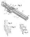
- the invention is amenable to implementation in a great variety of products. It can be embodied in a printer/plotter that includes a main case 1 (Fig. 1) with a window 2, and a left-hand pod 3 which encloses one end of the chassis. Within that enclosure are carriage-support and -drive mechanics and one end of the printing-medium advance mechanism, as well as a pen-refill station with supplemental ink cartridges.
- the printer/plotter also includes a printing-medium roll cover 4, and a receiving bin 5 for lengths or sheets of printing medium on which images have been formed, and which have been ejected from the machine.
- a bottom brace and storage shelf 6 spans the legs which support the two ends of the case 1.
- an entry slot 7 for receipt of continuous lengths of printing medium 4. Also included are a lever 8 for control of the gripping of the print medium by the machine.
- a front-panel display 11 and controls 12 are mounted in the skin of the right-hand pod 13. That pod encloses the right end of the carriage mechanics and of the medium advance mechanism, and also a printhead cleaning station. Near the bottom of the right-hand pod for readiest access is a standby switch 14.
- a cylindrical platen 41 (Fig. 2) - driven by a motor 42, worm 43 and worm gear 44 under control of signals from a digital electronic processor - rotates to drive sheets or lengths of printing medium 4A in a medium-advance direction. Print medium 4A is thereby drawn out of the print-medium roll cover 4.
- a pen-holding carriage assembly 20 carries pens back and forth across the printing medium, along a scanning track - perpendicular to the medium-advance direction - while the pens eject ink.
- the medium 4A thus receives inkdrops for formation of a desired image, and is ejected into the print-medium bin 5.
- the image may be a test pattern of numerous color patches or swatches 56, for reading by an optical sensor to generate calibration data.
- test patterns are for use in detecting positioning errors.
- a small automatic optoelectronic sensor 51 rides with the pens on the carriage and is directed downward to obtain data about pen condition (nozzle firing volume and direction, and interpen alignment).
- the sensor 51 can readily perform optical measurements 65, 81, 82 (Fig. 11); suitable algorithmic control 82 is well within the skill of the art, and may be guided by the discussions in the present document.
- a very finely graduated encoder strip 36 is extended taut along the scanning path of the carriage assembly 20 and read by another, very small automatic optoelectronic sensor 37 to provide position and speed information 37B for the microprocessor.
- One advantageous location for the encoder strip 36 is immediately behind the pens.
- a currently preferred position for the encoder strip 33 (Fig. 3), however, is near the rear of the pen-carriage tray - remote from the space into which a user's hands are inserted for servicing of the pen refill cartridges.
- the sensor 37 is disposed with its optical beam passing through orifices or transparent portions of a scale formed in the strip.
- the pen-carriage assembly 20 is driven in reciprocation by a motor 31 - along dual support and guide rails 32, 34 - through the intermediary of a drive belt 35.
- the motor 31 is under the control of signals from the digital processor.
- the pen-carriage assembly includes a forward bay structure 22 for pens - preferably at least four pens 23-26 holding ink of four different colors respectively. Most typically the inks are yellow in the leftmost pen 23, then cyan 24, magenta 25 and black 26.
- Another increasingly common system has inks of different colors that are actually different dilutions for one or more common chromatic colors, in the several pens.
- different dilutions of black may be in the several pens 23-26.
- both plural-chromatic-color and plural-black pens may be in a single printer, either in a common carriage or plural carriages.
- a rear tray 21 carrying various electronics.
- the colorimeter carriage too has a rear tray or extension 53 (Fig. 3), with a step 54 to clear the drive cables 35.
- Figs. 1 through 3 most specifically represent a system such as the Hewlett Packard printer/plotter model "DesignJet 2000CP", which does not include the present invention. These drawings, however, also illustrate certain embodiments of the invention, and - with certain detailed differences mentioned below - a printer/plotter that includes preferred embodiments of the invention.
- Preferred embodiments of the present invention vary the distance by which the print medium is advanced, in plural-pass printmodes.
- the advance is best changed frequently - in fact, most often it is changed between each pair of successive passes.
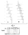
- the first operation described will be a three-pass mode that is conventional.
- the beginning b and end e of the swath are formed by the two ends of the overall printhead. As successive passes occur, inking is completed progressively for each swath segment.
- segments A , B and C are each partially inked during a first pass (Fig. 5) of the present example. Previous inking in the upper two segments A and B occurs in earlier passes, and the example here picks up with a representative segment C .
- the first pass shown in Fig. 5 is also the first pass in which segment C receives any ink.
- swath segments B , C and D are each partially inked; and in a third pass, swath segments C , D and E are each partially inked.
- segment C receives no ink at all in this pass; in other words, after the third pass, inking of segment C is finished.
- segment C is completely inked, from start to finish, in three passes - namely, the first, second and third passes of the first cycle. Each of these passes provides one-third of the total inking for segment C .
- Each of the other segments D , E , F , G and H similarly is inked in three passes - cycling between the numbered passes in the drawing thus: 123, then 231, 312, and then starting again with 123. Furthermore each pass is inked by the same groups of printing elements (nozzles). Each pass provides one-third of the total colorant placed on the printing medium.
- the interfaces (dashed horizontal lines i 1-2, i 2-3, i 3-1) between passes appear at a spatial periodicity of a third of the swath height.
- the spatial periodicity may also be expressed in reciprocal terms - that is, in terms of spatial frequency or wavenumber.
- the value (measured in "per-swathheight" units) is the reciprocal of the period - namely, three.
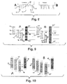
- Swath segment A will now be identified as two narrower segments J and K (Fig. 6). Remaining segments, too, are subdivided due to the effects of the printhead positions illustrated - yielding segments N through X - or previously printing positions not shown, to produce segments L and M .
- the advance differs between each successive pair of passes.
- regions of the swath that are completed by two, or three, or four passes: for example two for segment Q ; three for N , P , R and T ; four for O and S .
- the regions of the image are filled by cycling between passes thus: 12, 123, 1234, 234, 34, 3412, 12, 123 ....
- the number of possible combinations of nozzle groupings that print a region of the swath is larger (seven rather than only three).
- the scheme described here produces not only doubling of the spatial frequency but also elimination of coincident swath beginning and ends - for a printmode with any odd number of passes. For an even number of passes, the frequency-doubling effect is still obtained but in not the elimination of coincident swath boundaries.
- a third advantage is to increase the number of combinations of groups of nozzles that print each region of each swath.
- the number of combinations of nozzles that print each region is the same as the number of passes: in a three-pass mode each pixel row is printed with three nozzles - and those same three nozzles print a row in every swath.
- Varying the stroke allows more groups of nozzles to print each region, and the periodicity with which lines are printed by common nozzle groupings is greater than a single swath. This is an advantage because the more irregular the nozzle usage, the less susceptible to PAD error is the image quality.
- the printmode can be designed to complete the inking in three passes, or in three and a half.
- Bands are more visible if a defective nozzle or other printing element is paired with another defective nozzle than if paired with a nondefective nozzle.
- bands are more visible if two defective nozzles are grouped together with a nondefective nozzle than if they are separated into two groups, each with plural nondefective nozzles. Bands are also more visible if three or more defective nozzles are grouped together than if they are separated.
- Preferred embodiments of the invention break up patterns by refraining from always pairing the same two nozzles together to form a dot row.
- a poorly performing nozzle is paired with a well-performing nozzle (or region of such nozzles)
- the banding is inconspicuous, and may be hard to see even if an observer is looking for it.
- Varying the pairing of nozzles breaks up the repeating (e. g. 6 mm or quarter-inch) pattern. As already noted, this approach does not reduce the overall number of defects - but by breaking up repeated patterns it does make the defects much less noticeable.
- a conventional uniform-advance printmode (Fig. 7, left-hand "A" view) is subject to conspicuous banding for the reasons outlined above.
- the consistent pairing appears in the left-hand four columns of the accompanying Table.
- Varying the advance from 141 through 150 pixel rows makes available ten different nozzle pairings rather than only a single pairing for the uniform-advance mode. These varied pairings appear in the right-hand three columns (considered together with the pass number in the leftmost column) of the Table.
- nozzle number 201 (Fig. 7, right-hand "B" view) is paired with nozzle 51 - corresponding to the first row of the Table, as there listed for pass 1. Then as between the second and third passes, with an advance of only 144 rows, the same reference nozzle 201 is instead paired with nozzle 57 - corresponding to the second row of the Table, as listed for pass 2.
- This irregularity aims to provide significant though not necessarily maximum difference between the actual and nominal advances - and also between the actual advances used in succession. As passes 7 through 9 demonstrate, in general this goal cannot be attained consistently.
- One particularly satisfactory implementation is adjustment of the advance by multiples of two nozzle rows. Where a conventional advance is 96 nozzles for example, this strategy randomizes among 92, 94, 96, 98, and 100.
- Preferred embodiments of this form of the invention are not limited to two-pass printmodes, but rather are applicable as well to printmodes using more passes.
- Randomly varying the advance stroke helps to hide PAD errors by keeping them from repetitively falling in the same relative positions along the composite printed image. Following is an idea of how this works, in the same context previously discussed with reference to Fig. 9.
- P F ( P F 1 ⁇ U 1 + P F 2 ⁇ U 2 + ... ) / ( U 1 + U 2 + ... )
- the printer then applies the resultant weighted-mean PAD factor - which is very close to unity - to the nominal paper advance required for the next pass:
- FINAL ADVANCE NOMINAL ⁇ P F
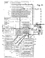
- Fig. 11 Before discussion of details in the block diagrammatic showing of Fig. 11, a general orientation to that drawing will be offered first.
- most portions 70, 73,75-78 across the center, including the printing stage 4A-51 at far right, are generally conventional and represent the context of the invention in an inkjet printer/plotter.
- top portion 63-72, 81-85 and certain parts 85, 61 of the central portions of the drawing represent most of the previously mentioned Doval invention relating to PAD-error accommodation. That material is essentially copied here because it too forms a part (though an optional part) of the environment of the present invention.
- the remaining central portions 170 and lower portions 171-188 of Fig. 11 relate to the present invention particularly.
- the three main blocks 171, 176, 181 are drawn overlapping to symbolize the conceptually overlapped character of functions in these blocks: the swath-edge spacing means 171, wavenumber (1/ ⁇ ) varying means 176 and nozzle-combination varying or increasing means 181 are most preferably integrated with one another, so that the corresponding main aspects of the invention are practiced in combination together.
- the pen-carriage assembly is represented separately at 20 (Fig. 11) when traveling to the left 16 while discharging ink 18, and at 20' when traveling to the right 17 while discharging ink 19. It will be understood that both 20 and 20' represent the same pen carriage.
- the previously mentioned digital processor 71 provides control signals 20B to fire the pens with correct timing, coordinated with platen drive control signals 42A to the platen motor 42, and carriage drive control signals 31A to the carriage drive motor 31.
- the processor 71 develops these carriage drive signals 31A based partly upon information about the carriage speed and position derived from the encoder signals 37B provided by the encoder 37.
- the codestrip 33 thus enables formation of color inkdrops at ultrahigh precision during scanning of the carriage assembly 20 in each direction - i. e., either left to right (forward 20') or right to left (back 20).
- New image data 70 are received 191 into an image-processing stage 73, which may conventionally include a contrast and color adjustment or correction module 76 and a rendition, scaling etc. module 77.
- a printmasking module 74 This may include a stage 61 for specific pass and nozzle assignments.
- the latter stage 61 performs generally conventional functions, but in accordance with certain aspects of the present invention is preferably constrained to printmodes that use very small numbers of passes - for example one-pass or two-pass modes.
- the invention is also amenable to use with greater numbers of passes as suggested by the notation "or 1- to n-pass" in block 61. Also within that block is an additional constraint 170 to printing a fully inked swath at each certain multiple of a half reciprocation of the carriage 20, 20' - not necessarily a preference but rather simply a condition to which are linked 189 certain preferred embodiments of the invention discussed below.
- half reciprocation means a single, unidirectional pass of the printhead carriage - as for example only from left to right, or only from right to left.
- values of the "certain multiple” include one, two and three; however, odd values are most highly preferred for swath-edge separation and for wavenumber raising, and for these purposes three may be ideal.
- a different choice may be more favorable for forms of the invention that use rotation or random variation among a relatively large number of step-distance values. In these cases, a "certain multiple" of one or two may be ideal since these provide the highest possible throughput.
- These features include the swath-edge spacing means 172 discussed in section 2 above. Associated with these means are the spacing-distance randomizing means 173, which is most particularly associated with the algorithm-adapting means 174 and its link to the algorithm block 85.
- the latter block 85 is connected 187, 196 to control the final output stage 78, particularly in regard to its generation of the print-medium advance signals 42A. All of the other features 175-188, however, can also be implemented in this same way - even though they are not so illustrated.
- a preferred form of the edge spacing means 172 includes means 175 for spacing of the edges distinctly well away from one another.
- Preferred values of such spacing include at least a twentieth of the PAD dimension of the swath - i. e. the dimension of the swath in the printing-medium advance direction. Spacing the edges apart by a tenth of the swath PAD dimension is still more preferable in practice, as it corresponds to a printmode using a smaller number of passes.
- Preferred embodiments of the invention also include means 176 for raising the spatial frequency or "wavenumber" of the banding in printed images.
- the accepted wavenumber notation "1/ ⁇ " has been used to represent spatial frequency, " ⁇ ” to represent variation, and "2 ⁇ ” to represent doubling.
- the spatial-frequency varying means 176 appear labeled as ⁇ (1/ ⁇ ) and the preferred spatial-frequency doubling means 177 as 2 ⁇ (1/ ⁇ ).
- the remaining means 181 are for varying the number of nozzle combinations used to print an image. Generally speaking such variation preferably takes the form of an increase.
- these means 181 include means 185 for varying the length of the step or stroke between the swaths.
- These latter means 185 in turn include means 184 for providing such variation at each step.
- these stepwise varying means 184 include means 183 for alternating between two distinct values.
- these means 183 are linked 189 at least conceptually to the use of a three-pass mode, which as shown by the example earlier is one preferred way of operating the pass/assignment block 61.
- the alternating means 183 are particularly well implemented 183' with one-sixth and one-half swath PAD dimension steps.
- Another preferred form of the stepwise varying means 184 takes the form of means for varying in accordance with the function (2 n - 1)/2 N as previously mentioned, with n ranging from 1 through N , and the value N (the number of passes) preferably odd as the drawing is intended to connote.
- the means represented by the several blocks 171, 176, 181 as shown are implemented within integrated circuits 71. Given the statements of function and the swath diagrams presented in this document, an experienced programmer of ordinary skill in this field can prepare suitable programs for operation of the circuits.
- the integrated circuits 71 may be part of the printer itself, as for example an application-specific integrated circuit (ASIC), or may be program data in a read-only memory (ROM) - or during operation may be parts of a programmed configuration of operating modules in the central processing unit (CPU) of a general-purpose computer that reads instructions from a hard drive.
- ASIC application-specific integrated circuit
- ROM read-only memory
- CPU central processing unit
- RIP raster image processor
- the system retrieves 101 (Fig. 12) its operating program appropriately - i. e., by reading instructions from memory in case of a firmware or software implementation, or by simply operating dedicated hardware in case of an ASIC or like implementation.
- the method proceeds to iterate 118 the operational steps 102-117, 122-124.
Landscapes
- Engineering & Computer Science (AREA)
- Quality & Reliability (AREA)
- Ink Jet (AREA)
Applications Claiming Priority (2)
| Application Number | Priority Date | Filing Date | Title |
|---|---|---|---|
| US09/516,816 US6336702B1 (en) | 2000-03-01 | 2000-03-01 | Banding reduction in incremental printing, by spacing-apart of swath edges and randomly selected print-medium advance |
| US516816 | 2000-03-01 |
Publications (3)
| Publication Number | Publication Date |
|---|---|
| EP1132213A2 EP1132213A2 (en) | 2001-09-12 |
| EP1132213A3 EP1132213A3 (en) | 2002-10-23 |
| EP1132213B1 true EP1132213B1 (en) | 2006-06-28 |
Family
ID=24057204
Family Applications (1)
| Application Number | Title | Priority Date | Filing Date |
|---|---|---|---|
| EP01105018A Expired - Lifetime EP1132213B1 (en) | 2000-03-01 | 2001-03-01 | Banding reduction in incremental printing |
Country Status (4)
| Country | Link |
|---|---|
| US (2) | US6336702B1 (enExample) |
| EP (1) | EP1132213B1 (enExample) |
| JP (1) | JP2001328250A (enExample) |
| DE (1) | DE60121079T2 (enExample) |
Families Citing this family (22)
| Publication number | Priority date | Publication date | Assignee | Title |
|---|---|---|---|---|
| US6336702B1 (en) * | 2000-03-01 | 2002-01-08 | Hewlett-Packard Company | Banding reduction in incremental printing, by spacing-apart of swath edges and randomly selected print-medium advance |
| US7027185B2 (en) * | 2001-07-30 | 2006-04-11 | Hewlett-Packard Development Company, L.P. | Linearization of an incremental printer by measurements referred to a media-independent sensor calibration |
| US6786569B2 (en) | 2001-10-31 | 2004-09-07 | Agfa-Gevaert | Printing methods and apparatus for reducing banding due to paper transport |
| EP1642723B1 (en) | 2001-10-31 | 2012-05-23 | Agfa Graphics N.V. | Printing methods and apparatus for reducing banding due to paper transport |
| US7008209B2 (en) * | 2002-07-03 | 2006-03-07 | Therics, Llc | Apparatus, systems and methods for use in three-dimensional printing |
| US6695435B1 (en) * | 2003-05-30 | 2004-02-24 | Xerox Corporation | Selective replacement for artifact reduction |
| US7036904B2 (en) * | 2003-10-30 | 2006-05-02 | Lexmark International, Inc. | Printhead swath height measurement and compensation for ink jet printing |
| US6935795B1 (en) | 2004-03-17 | 2005-08-30 | Lexmark International, Inc. | Method for reducing the effects of printhead carrier disturbance during printing with an imaging apparatus |
| JP4217651B2 (ja) * | 2004-03-31 | 2009-02-04 | キヤノン株式会社 | インクジェット記録装置 |
| US7118191B2 (en) * | 2004-06-28 | 2006-10-10 | Lexmark International, Inc. | Apparatus and method for ink jet printing using variable interlacing |
| US20060061607A1 (en) * | 2004-09-21 | 2006-03-23 | Marra Michael A Iii | Method for facilitating swath height compensation for a printhead |
| US20060164697A1 (en) * | 2005-01-26 | 2006-07-27 | Larson David R | Irregularly spacing linear portions of media sheet for optical scanning thereof |
| DE602006001821D1 (de) * | 2005-10-27 | 2008-08-28 | Oce Tech Bv | Antriebsmechanismus für eine Zuführrolle in einem Drucker |
| DE602006005760D1 (de) * | 2005-10-27 | 2009-04-30 | Oce Tech Bv | Drucker mit schneckengetriebener Zuführwalze |
| US7431522B2 (en) * | 2006-01-17 | 2008-10-07 | Lexmark International, Inc | Method for reducing banding in an imaging apparatus |
| US7845751B2 (en) * | 2008-10-15 | 2010-12-07 | Eastman Kodak Company | Nonuniform mask circulation for irregular page advance |
| CN102239054B (zh) * | 2008-12-03 | 2014-02-12 | 录象射流技术公司 | 喷墨打印系统和方法 |
| EP2960062B1 (en) | 2014-06-26 | 2017-02-01 | OCE-Technologies B.V. | Method for calibrating accurate paper steps |
| WO2016167790A1 (en) | 2015-04-17 | 2016-10-20 | Hewlett-Packard Development Company, L.P. | Random wave mask generation |
| US20210311081A1 (en) * | 2018-11-02 | 2021-10-07 | Hewlett-Packard Development Company, L.P. | Randomized dispensing order |
| US11660631B2 (en) * | 2021-05-05 | 2023-05-30 | Oav Equipment And Tools, Inc. | Glue applying mechanism of edge banding machine with glue quantity regulator |
| US11541415B2 (en) * | 2021-05-26 | 2023-01-03 | Oav Equipment And Tools, Inc. | Glue applying mechanism of edge banding machine for applying glue to workpiece having oblique surface and edge banding machine using the glue applying mechanism |
Family Cites Families (10)
| Publication number | Priority date | Publication date | Assignee | Title |
|---|---|---|---|---|
| US4920355A (en) * | 1989-07-31 | 1990-04-24 | Eastman Kodak Company | Interlace method for scanning print head systems |
| US5790150A (en) * | 1994-02-17 | 1998-08-04 | Colorspan Corporation | Method for controlling an ink jet printer in a multipass printing mode |
| US5805183A (en) * | 1994-11-10 | 1998-09-08 | Lasermaster Corporation | Ink jet printer with variable advance interlacing |
| US6086181A (en) * | 1996-07-02 | 2000-07-11 | Hewlett-Packard Company | Maximum-diagonal print mask and multipass printing modes, for high quality and high throughput with liquid-base inks |
| US5940093A (en) * | 1997-03-14 | 1999-08-17 | Lexmark International, Inc. | Method of printing with an ink jet printer to inhibit the formation of a print artifact |
| JP4193216B2 (ja) * | 1997-04-08 | 2008-12-10 | セイコーエプソン株式会社 | ドット記録方法およびドット記録装置 |
| US6170932B1 (en) * | 1997-05-20 | 2001-01-09 | Seiko Epson Corporation | Printing system, method of printing, and recording medium to realize the method |
| JP3639703B2 (ja) * | 1997-11-14 | 2005-04-20 | キヤノン株式会社 | インクジェット記録装置およびインクジェット記録方法 |
| JP3440804B2 (ja) * | 1998-01-23 | 2003-08-25 | セイコーエプソン株式会社 | 印刷装置および印刷方法並びに記録媒体 |
| US6336702B1 (en) * | 2000-03-01 | 2002-01-08 | Hewlett-Packard Company | Banding reduction in incremental printing, by spacing-apart of swath edges and randomly selected print-medium advance |
-
2000
- 2000-03-01 US US09/516,816 patent/US6336702B1/en not_active Expired - Fee Related
-
2001
- 2001-03-01 EP EP01105018A patent/EP1132213B1/en not_active Expired - Lifetime
- 2001-03-01 DE DE60121079T patent/DE60121079T2/de not_active Expired - Lifetime
- 2001-03-01 JP JP2001057394A patent/JP2001328250A/ja not_active Withdrawn
- 2001-11-02 US US10/012,281 patent/US6523936B2/en not_active Expired - Fee Related
Also Published As
| Publication number | Publication date |
|---|---|
| US6336702B1 (en) | 2002-01-08 |
| JP2001328250A (ja) | 2001-11-27 |
| EP1132213A3 (en) | 2002-10-23 |
| US20020041306A1 (en) | 2002-04-11 |
| DE60121079T2 (de) | 2006-12-28 |
| EP1132213A2 (en) | 2001-09-12 |
| US6523936B2 (en) | 2003-02-25 |
| DE60121079D1 (de) | 2006-08-10 |
Similar Documents
| Publication | Publication Date | Title |
|---|---|---|
| EP1132213B1 (en) | Banding reduction in incremental printing | |
| EP0730246B1 (en) | Method of transitioning between ink jet printing modes | |
| EP0863478B1 (en) | Method and apparatus for multipass ink jet printing | |
| JP5322436B2 (ja) | より高速なインクジェット印刷のための手段 | |
| US6367908B1 (en) | High-resolution inkjet printing using color drop placement on every pixel row during a single pass | |
| US6848765B1 (en) | End-of-page advance-distance decrease, in liquid-ink printers | |
| US6375307B1 (en) | Printing apparatus and method | |
| EP0863480B1 (en) | Method and apparatus for multipass colour ink jet printing | |
| JP2008509023A5 (enExample) | ||
| US6250739B1 (en) | Bidirectional color printmodes with semistaggered swaths to minimize hue shift and other artifacts | |
| EP1029693B1 (en) | Printing with multiple passes | |
| US20080150979A1 (en) | Ink jet printing apparatus and ink jet printing method | |
| US6296343B1 (en) | Edge enhancement depletion technique for over-sized ink drops to achieve high resolution X/Y axes addressability in inkjet printing | |
| US5821957A (en) | Method of ink jet printing using color fortification in black regions | |
| US6142605A (en) | Bidirectional color printing using multipass printmodes with at least partially swath-aligned inkjet printheads | |
| US6425699B1 (en) | Use of very small advances of printing medium for improved image quality in incremental printing | |
| US6712443B2 (en) | Ink jet recording apparatus and ink jet recording method | |
| EP1130540B1 (en) | Banding reduction in incremental printing, through use of like weights for complementary printhead regions | |
| JPH10157094A (ja) | 高解像度のx/y軸アドレス指定能力を達成するための過大インク滴に関するカラーインクジェット削減技法 | |
| JP2007015269A (ja) | 記録装置および記録位置制御方法 | |
| JPH10157171A (ja) | インクジェットプリントにおける高解像度のx/y軸アドレス指定能力のためのプロットに依存しない領域充填削減技法 | |
| JP4133014B2 (ja) | 搬送ずれ検出用印字パターン印字方法 | |
| JPH10157095A (ja) | カラーインクジェットプリントにおける高解像度のアドレス指定能力のための外部寸法の完全性 | |
| EP1076881B1 (en) | Method of interlaced printing using an inkjet printer | |
| JPH10226096A (ja) | 低解像度インクジェットプリントヘッドを使用して高解像度のx/y軸アドレス指定能力を達成する多色スワスプリント技法 |
Legal Events
| Date | Code | Title | Description |
|---|---|---|---|
| PUAI | Public reference made under article 153(3) epc to a published international application that has entered the european phase |
Free format text: ORIGINAL CODE: 0009012 |
|
| AK | Designated contracting states |
Kind code of ref document: A2 Designated state(s): AT BE CH CY DE DK ES FI FR GB GR IE IT LI LU MC NL PT SE TR |
|
| AX | Request for extension of the european patent |
Free format text: AL;LT;LV;MK;RO;SI |
|
| PUAL | Search report despatched |
Free format text: ORIGINAL CODE: 0009013 |
|
| AK | Designated contracting states |
Kind code of ref document: A3 Designated state(s): AT BE CH CY DE DK ES FI FR GB GR IE IT LI LU MC NL PT SE TR |
|
| AX | Request for extension of the european patent |
Free format text: AL;LT;LV;MK;RO;SI |
|
| RIC1 | Information provided on ipc code assigned before grant |
Free format text: 7B 41J 2/21 A, 7B 41J 19/78 B |
|
| 17P | Request for examination filed |
Effective date: 20030410 |
|
| AKX | Designation fees paid |
Designated state(s): DE ES GB IT |
|
| 17Q | First examination report despatched |
Effective date: 20030723 |
|
| GRAP | Despatch of communication of intention to grant a patent |
Free format text: ORIGINAL CODE: EPIDOSNIGR1 |
|
| GRAS | Grant fee paid |
Free format text: ORIGINAL CODE: EPIDOSNIGR3 |
|
| GRAA | (expected) grant |
Free format text: ORIGINAL CODE: 0009210 |
|
| AK | Designated contracting states |
Kind code of ref document: B1 Designated state(s): DE ES GB IT |
|
| PG25 | Lapsed in a contracting state [announced via postgrant information from national office to epo] |
Ref country code: IT Free format text: LAPSE BECAUSE OF FAILURE TO SUBMIT A TRANSLATION OF THE DESCRIPTION OR TO PAY THE FEE WITHIN THE PRESCRIBED TIME-LIMIT;WARNING: LAPSES OF ITALIAN PATENTS WITH EFFECTIVE DATE BEFORE 2007 MAY HAVE OCCURRED AT ANY TIME BEFORE 2007. THE CORRECT EFFECTIVE DATE MAY BE DIFFERENT FROM THE ONE RECORDED. Effective date: 20060628 |
|
| REG | Reference to a national code |
Ref country code: GB Ref legal event code: FG4D |
|
| REF | Corresponds to: |
Ref document number: 60121079 Country of ref document: DE Date of ref document: 20060810 Kind code of ref document: P |
|
| PG25 | Lapsed in a contracting state [announced via postgrant information from national office to epo] |
Ref country code: ES Free format text: LAPSE BECAUSE OF FAILURE TO SUBMIT A TRANSLATION OF THE DESCRIPTION OR TO PAY THE FEE WITHIN THE PRESCRIBED TIME-LIMIT Effective date: 20061009 |
|
| PLBE | No opposition filed within time limit |
Free format text: ORIGINAL CODE: 0009261 |
|
| STAA | Information on the status of an ep patent application or granted ep patent |
Free format text: STATUS: NO OPPOSITION FILED WITHIN TIME LIMIT |
|
| 26N | No opposition filed |
Effective date: 20070329 |
|
| REG | Reference to a national code |
Ref country code: GB Ref legal event code: 732E Free format text: REGISTERED BETWEEN 20120329 AND 20120404 |
|
| PGFP | Annual fee paid to national office [announced via postgrant information from national office to epo] |
Ref country code: GB Payment date: 20130228 Year of fee payment: 13 Ref country code: DE Payment date: 20130221 Year of fee payment: 13 |
|
| REG | Reference to a national code |
Ref country code: DE Ref legal event code: R119 Ref document number: 60121079 Country of ref document: DE |
|
| GBPC | Gb: european patent ceased through non-payment of renewal fee |
Effective date: 20140301 |
|
| REG | Reference to a national code |
Ref country code: DE Ref legal event code: R119 Ref document number: 60121079 Country of ref document: DE Effective date: 20141001 |
|
| PG25 | Lapsed in a contracting state [announced via postgrant information from national office to epo] |
Ref country code: DE Free format text: LAPSE BECAUSE OF NON-PAYMENT OF DUE FEES Effective date: 20141001 Ref country code: GB Free format text: LAPSE BECAUSE OF NON-PAYMENT OF DUE FEES Effective date: 20140301 |