EP1132062A1 - Einzementierbare Schaftprothese - Google Patents
Einzementierbare Schaftprothese Download PDFInfo
- Publication number
- EP1132062A1 EP1132062A1 EP01810125A EP01810125A EP1132062A1 EP 1132062 A1 EP1132062 A1 EP 1132062A1 EP 01810125 A EP01810125 A EP 01810125A EP 01810125 A EP01810125 A EP 01810125A EP 1132062 A1 EP1132062 A1 EP 1132062A1
- Authority
- EP
- European Patent Office
- Prior art keywords
- centering device
- shaft end
- cavity
- prosthesis
- shaft
- Prior art date
- Legal status (The legal status is an assumption and is not a legal conclusion. Google has not performed a legal analysis and makes no representation as to the accuracy of the status listed.)
- Granted
Links
- 239000004568 cement Substances 0.000 title description 8
- 229920003023 plastic Polymers 0.000 claims abstract description 6
- 239000004033 plastic Substances 0.000 claims abstract description 6
- 238000002347 injection Methods 0.000 claims description 4
- 239000007924 injection Substances 0.000 claims description 4
- 229920003229 poly(methyl methacrylate) Polymers 0.000 claims description 4
- 239000004926 polymethyl methacrylate Substances 0.000 claims description 4
- 239000002639 bone cement Substances 0.000 description 7
- 238000007654 immersion Methods 0.000 description 4
- 239000007788 liquid Substances 0.000 description 4
- 238000004519 manufacturing process Methods 0.000 description 3
- 230000035515 penetration Effects 0.000 description 3
- 239000004698 Polyethylene Substances 0.000 description 1
- 210000000988 bone and bone Anatomy 0.000 description 1
- 230000001419 dependent effect Effects 0.000 description 1
- 238000011161 development Methods 0.000 description 1
- 230000018109 developmental process Effects 0.000 description 1
- 230000000694 effects Effects 0.000 description 1
- 210000002391 femur head Anatomy 0.000 description 1
- 239000000463 material Substances 0.000 description 1
- 230000013011 mating Effects 0.000 description 1
- 239000002184 metal Substances 0.000 description 1
- 230000002093 peripheral effect Effects 0.000 description 1
- -1 polyethylene Polymers 0.000 description 1
- 229920000573 polyethylene Polymers 0.000 description 1
- 238000007789 sealing Methods 0.000 description 1
- 210000000689 upper leg Anatomy 0.000 description 1
Images


Classifications
-
- A—HUMAN NECESSITIES
- A61—MEDICAL OR VETERINARY SCIENCE; HYGIENE
- A61F—FILTERS IMPLANTABLE INTO BLOOD VESSELS; PROSTHESES; DEVICES PROVIDING PATENCY TO, OR PREVENTING COLLAPSING OF, TUBULAR STRUCTURES OF THE BODY, e.g. STENTS; ORTHOPAEDIC, NURSING OR CONTRACEPTIVE DEVICES; FOMENTATION; TREATMENT OR PROTECTION OF EYES OR EARS; BANDAGES, DRESSINGS OR ABSORBENT PADS; FIRST-AID KITS
- A61F2/00—Filters implantable into blood vessels; Prostheses, i.e. artificial substitutes or replacements for parts of the body; Appliances for connecting them with the body; Devices providing patency to, or preventing collapsing of, tubular structures of the body, e.g. stents
- A61F2/02—Prostheses implantable into the body
- A61F2/30—Joints
- A61F2/30721—Accessories
- A61F2/30724—Spacers for centering an implant in a bone cavity, e.g. in a cement-receiving cavity
-
- A—HUMAN NECESSITIES
- A61—MEDICAL OR VETERINARY SCIENCE; HYGIENE
- A61F—FILTERS IMPLANTABLE INTO BLOOD VESSELS; PROSTHESES; DEVICES PROVIDING PATENCY TO, OR PREVENTING COLLAPSING OF, TUBULAR STRUCTURES OF THE BODY, e.g. STENTS; ORTHOPAEDIC, NURSING OR CONTRACEPTIVE DEVICES; FOMENTATION; TREATMENT OR PROTECTION OF EYES OR EARS; BANDAGES, DRESSINGS OR ABSORBENT PADS; FIRST-AID KITS
- A61F2/00—Filters implantable into blood vessels; Prostheses, i.e. artificial substitutes or replacements for parts of the body; Appliances for connecting them with the body; Devices providing patency to, or preventing collapsing of, tubular structures of the body, e.g. stents
- A61F2/02—Prostheses implantable into the body
- A61F2/30—Joints
- A61F2/3094—Designing or manufacturing processes
-
- A—HUMAN NECESSITIES
- A61—MEDICAL OR VETERINARY SCIENCE; HYGIENE
- A61F—FILTERS IMPLANTABLE INTO BLOOD VESSELS; PROSTHESES; DEVICES PROVIDING PATENCY TO, OR PREVENTING COLLAPSING OF, TUBULAR STRUCTURES OF THE BODY, e.g. STENTS; ORTHOPAEDIC, NURSING OR CONTRACEPTIVE DEVICES; FOMENTATION; TREATMENT OR PROTECTION OF EYES OR EARS; BANDAGES, DRESSINGS OR ABSORBENT PADS; FIRST-AID KITS
- A61F2/00—Filters implantable into blood vessels; Prostheses, i.e. artificial substitutes or replacements for parts of the body; Appliances for connecting them with the body; Devices providing patency to, or preventing collapsing of, tubular structures of the body, e.g. stents
- A61F2/02—Prostheses implantable into the body
- A61F2/30—Joints
- A61F2/32—Joints for the hip
- A61F2/36—Femoral heads ; Femoral endoprostheses
- A61F2/3662—Femoral shafts
- A61F2/3676—Distal or diaphyseal parts of shafts
-
- A—HUMAN NECESSITIES
- A61—MEDICAL OR VETERINARY SCIENCE; HYGIENE
- A61F—FILTERS IMPLANTABLE INTO BLOOD VESSELS; PROSTHESES; DEVICES PROVIDING PATENCY TO, OR PREVENTING COLLAPSING OF, TUBULAR STRUCTURES OF THE BODY, e.g. STENTS; ORTHOPAEDIC, NURSING OR CONTRACEPTIVE DEVICES; FOMENTATION; TREATMENT OR PROTECTION OF EYES OR EARS; BANDAGES, DRESSINGS OR ABSORBENT PADS; FIRST-AID KITS
- A61F2/00—Filters implantable into blood vessels; Prostheses, i.e. artificial substitutes or replacements for parts of the body; Appliances for connecting them with the body; Devices providing patency to, or preventing collapsing of, tubular structures of the body, e.g. stents
- A61F2/02—Prostheses implantable into the body
- A61F2/30—Joints
- A61F2002/30001—Additional features of subject-matter classified in A61F2/28, A61F2/30 and subgroups thereof
- A61F2002/30316—The prosthesis having different structural features at different locations within the same prosthesis; Connections between prosthetic parts; Special structural features of bone or joint prostheses not otherwise provided for
- A61F2002/30329—Connections or couplings between prosthetic parts, e.g. between modular parts; Connecting elements
- A61F2002/30331—Connections or couplings between prosthetic parts, e.g. between modular parts; Connecting elements made by longitudinally pushing a protrusion into a complementarily-shaped recess, e.g. held by friction fit
- A61F2002/30332—Conically- or frustoconically-shaped protrusion and recess
-
- A—HUMAN NECESSITIES
- A61—MEDICAL OR VETERINARY SCIENCE; HYGIENE
- A61F—FILTERS IMPLANTABLE INTO BLOOD VESSELS; PROSTHESES; DEVICES PROVIDING PATENCY TO, OR PREVENTING COLLAPSING OF, TUBULAR STRUCTURES OF THE BODY, e.g. STENTS; ORTHOPAEDIC, NURSING OR CONTRACEPTIVE DEVICES; FOMENTATION; TREATMENT OR PROTECTION OF EYES OR EARS; BANDAGES, DRESSINGS OR ABSORBENT PADS; FIRST-AID KITS
- A61F2/00—Filters implantable into blood vessels; Prostheses, i.e. artificial substitutes or replacements for parts of the body; Appliances for connecting them with the body; Devices providing patency to, or preventing collapsing of, tubular structures of the body, e.g. stents
- A61F2/02—Prostheses implantable into the body
- A61F2/30—Joints
- A61F2002/30001—Additional features of subject-matter classified in A61F2/28, A61F2/30 and subgroups thereof
- A61F2002/30316—The prosthesis having different structural features at different locations within the same prosthesis; Connections between prosthetic parts; Special structural features of bone or joint prostheses not otherwise provided for
- A61F2002/30329—Connections or couplings between prosthetic parts, e.g. between modular parts; Connecting elements
- A61F2002/30331—Connections or couplings between prosthetic parts, e.g. between modular parts; Connecting elements made by longitudinally pushing a protrusion into a complementarily-shaped recess, e.g. held by friction fit
- A61F2002/30332—Conically- or frustoconically-shaped protrusion and recess
- A61F2002/30336—Stepped cones, i.e. having discrete diameter changes
-
- A—HUMAN NECESSITIES
- A61—MEDICAL OR VETERINARY SCIENCE; HYGIENE
- A61F—FILTERS IMPLANTABLE INTO BLOOD VESSELS; PROSTHESES; DEVICES PROVIDING PATENCY TO, OR PREVENTING COLLAPSING OF, TUBULAR STRUCTURES OF THE BODY, e.g. STENTS; ORTHOPAEDIC, NURSING OR CONTRACEPTIVE DEVICES; FOMENTATION; TREATMENT OR PROTECTION OF EYES OR EARS; BANDAGES, DRESSINGS OR ABSORBENT PADS; FIRST-AID KITS
- A61F2220/00—Fixations or connections for prostheses classified in groups A61F2/00 - A61F2/26 or A61F2/82 or A61F9/00 or A61F11/00 or subgroups thereof
- A61F2220/0025—Connections or couplings between prosthetic parts, e.g. between modular parts; Connecting elements
- A61F2220/0033—Connections or couplings between prosthetic parts, e.g. between modular parts; Connecting elements made by longitudinally pushing a protrusion into a complementary-shaped recess, e.g. held by friction fit
Definitions
- the invention relates to a cemented stem prosthesis with a at its distal shaft end attachable centering device Plastic, which forms a cavity to the distal shaft end, whereby a conical between the distal shaft end and the centering device Clamping connection exists, which in the distal direction a deeper sinking of the allows distal shaft end in the cavity.
- a centering device for the distal end of a cementable prosthetic socket shown on the distal end is attachable and a cavity for the distal end forms so that the distal end to avoid cracks in the hardened Cement can sink deeper into the cavity.
- Plastics such as polyethylene are provided for the centering device.
- This proposed design has the disadvantage that the distal end, which is conical in its very narrow tolerances Outside contour must be machined in order to clamp in the axial direction and to guarantee slipping as the axial force increases. This kind the clamping causes such a great sealing effect at the same time, that a vent hole at the lowest point of the cavity is proposed.
- Another disadvantage is that thick Shaft ends that are used to maintain a uniformly thin cement jacket would be desirable in the medullary cavity, large ones in the distal area Surface portions with a relatively large half cone angle Have surface to the shaft axis.
- the invention has the advantage that the outer contour of the distal Prosthesis end no longer has a management function and that the cavity the centering device by a weak line contact between their proximal peripheral edge and the surface of the shaft can be kept cement-free. Another advantage is that Safety of the clamping and positioning of the centering device on the Pin, because the cone angle is freely selectable and there is a conical hole in the distal shaft end is inexpensive to manufacture in close tolerances.
- the half cone angle of the conical bore can vary from Shaft and centering device and according to the geometry of the pin between 0.5 ° and 2.5 ° can be selected.
- a metallic shaft and one Centering device made of plastic, for example made of PMMA (Polymethyl methacrylate) half the cone angle can be between 1.2 ° and 1.6 ° lie.
- the pin has two steps with different diameters, and the gradation to the axial distance is chosen so that it is half Cone angle of the conical bore coincides, then arise at Attach the centering device two axially spaced guide and Clamping zones that correspond to the friction and half the cone angle between conical bore and pin in the axial direction Oppose resistance F, which with increasing immersion the shaft tip grows disproportionately. Immersion is practically only possible because the steps of the pin are radially inward deform.
- the distance between the steps is chosen so that initially there is only one step at the conical bore and if this step is because for example, it is formed from just a few ribs, becoming radially lighter deforms, then arises when the centering device is attached At first only a small axial resistance, which is only much stronger grows, even if the second stage with further immersion of the distal Shaft tip is deformed radially inwards. That means when plugging in the centering device keeps itself on the tip of the shaft and forms a noticeable resistance when the centering device is aligned with its pin has reached a designated position.
- the prosthetic socket can then be integrated into one with the centering device Insert bone cement filled medullary canal and is at its distal end by at least three fins Centering device guided.
- the target position of the centering device becomes even more striking when it is attached signals when the conical bore has an inlet cone with something has a larger half cone angle and the second step on this steeper cone and for further penetration into the conical Hole must first be radially deformed on this steeper cone.
- the cavity in the centering device and the axial resistance are dimensioned so that the distal shaft end after attachment and Cement several millimeters later into the centering device can immerse without the enclosed by bone cement Jacket of the centering device experiences impermissible forces in the axial direction.
- the figures show a stem prosthesis 1 that can be cemented in place their distal shaft end 3 pluggable centering device 2 Plastic, which forms a cavity 4 to the distal shaft end 3.
- a clamp connection There is between the distal shaft end 3 and the centering device 2 a clamp connection, the deeper sinking in the distal direction Shaft end allows in the cavity.
- the clamp connection is through a pin 7 formed in the cavity 4 on the centering device 2 reached, which in the proximal direction in a conical bore 5 of Shaft end 3 protrudes.
- femoral shaft prosthesis 1 at its distal shaft end 3 a snap-on centering device 2.
- the femur 21 is provided with a medullary block 20 in its medullary height 25, which seals against liquid bone 19 filled in.
- Prosthesis 1 and Centering devices are placed together in the liquid bone cement 19th lowered until the intended penetration depth is reached.
- the distal shaft end 3 is lowered by fins 22, 24 within the Medullary cavity 25 centered.
- a fin 24 is against lateral aligned.
- the centering device 2 in FIGS. 2 and 3 only has 26 with its upper edge still a slight line contact to the shaft end 3 to penetrate to prevent liquid bone cement.
- the actual fixation happens through a in a cavity 4 on the centering device 2 molded pin 7, which in a conical, in the proximal direction Shaft 3 attached bore 5 is clamped.
- the pin has a first stage with attached Ribs 16, 17, 18 which in the unstressed state have a diameter of 10 are limited to a little under the diameter 12 one subsequent second stage 11.
- the position of the pin 7 in Figure 2 corresponds to a desired plug-on position in which the ribs 16, 17, 18th are already deformed radially inwards to the extent that a desired one Clamping force against pulling out is reached.
- the second stage 11 with its slightly larger diameter in an inlet cone 30 the conical bore 5 centers and forms an additional and good noticeable resistance to further penetration of the pin 7. Only at the second becomes a much greater axial force of the shaft end 3 Level 11 deformed radially inwards and the shaft end 3 can against a intended resistance force deeper into the cavity 4 of the Immerse centering device 2.
- the cavity 4 and the conical bore 5 are dimensioned so that the shaft after attaching the Centering device 2 against a higher resistance several more Millimeter can immerse in the centering device 2.
- This "jump" in Resistance has the advantage that the centering device 2 during the Guide and lower the prosthesis socket 1 in the liquid bone cement 19 no longer pushes onto the shaft.
- To the centering device only to be able to touch down when a fin 24 is against lateral is one offset surface 27 parallel to shaft axis 31 at shaft end 3 attached, which ends in a nose 32.
- the centering device has a matching guide surface 28 in the cavity 4, which is a twist prevented.
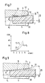
- FIGS. 4, 5, 6 show an arrangement in which the inlet cone 30 with its half cone angle 29 does not contribute to the increase in the resistance force F in the axial direction.
- the first step 9 with a point P 1 on the diameter 10 of the rib 17 first touches the conical bore 5, while the axial distance 14 for a point P 2 with a diameter 12 of the second step 11 is dimensioned such that the Point P 2 has not yet touched the conical bore 5.
- the ribs 17 are deformed radially inward at point P 1 and a clamping and guiding zone 13 (FIG. 5) is created with a weakly increasing clamping force.
- FIG. 8 shows a graph in which the resistance force F is plotted over a path S in the axial direction.
- the additional intervention from point P 2 results in a steeper increase in the resistance force F.
- a jump 33 initially occurs with the additional intervention from a point P 2 ' in the increase in force, which is followed by a steeper increase.
- FIG. 9 shows a further arrangement in which the second stage 11, which is provided with ribs 17, comes into engagement with the conical bore 5 with a point P 3 , while the first stage with a point P 4 still has some play has conical bore 5.
- the rib 17 is first deformed inward in order to clamp the pin 7. Only when point P 4 rests on conical bore 5 is a kink with a steeper increase in resistance force F generated when the movement continues.
- the size of the axial resistance force can be defined by the shape or by the contour, the diameters 10, 12 and the axial distance 14 of the two steps 9, 11, which determine their yield in the radial direction, and by the size of the half cone angle 8 become.
Landscapes
- Health & Medical Sciences (AREA)
- Orthopedic Medicine & Surgery (AREA)
- Cardiology (AREA)
- Oral & Maxillofacial Surgery (AREA)
- Transplantation (AREA)
- Engineering & Computer Science (AREA)
- Biomedical Technology (AREA)
- Heart & Thoracic Surgery (AREA)
- Vascular Medicine (AREA)
- Life Sciences & Earth Sciences (AREA)
- Animal Behavior & Ethology (AREA)
- General Health & Medical Sciences (AREA)
- Public Health (AREA)
- Veterinary Medicine (AREA)
- Prostheses (AREA)
Abstract
Description
- Fig. 1
- Schematisch eine Ansicht auf eine Femurschaftprothese mit einer Zentriervorrichtung;
- Fig. 2
- schematisch einen vergrösserten Ausschnitt des Schaftendes von Figur 1 mit der Zentriervorrichtung;
- Fig. 3
- schematisch eine Draufsicht auf die Zentriervorrichtung von Figur 2;
- Fig. 4
- schematisch, stark vergrössert und in den Winkeln überhöht einen Ausschnitt von einem Zapfen beim Beginn des Aufliegens in einer konischen Bohrung;
- Fig. 5
- schematisch die Anordnung von Figur 4 beim Beginn des Aufliegens einer zweiten Stufe in der konischen Bohrung;
- Fig. 6
- schematisch die Anordnung von Figur 5, beim weiteren Einfahren des Zapfens;
- Fig. 7
- schematisch eine weitere Anordnung wie in Figur 2, bei der die zweite Stufe zunächst an einem Einlaufkonus aufliegt;
- Fig. 8
- schematisch eine Grafik für die Widerstandskraft in axialer Richtung beim Einpressen eines Zapfens; und
- Fig. 9
- schematisch eine Anordnung analog zu Figur 5, bei der die zweite Stufe mit einem Punkt P3 als Erste in der konischen Bohrung aufliegt.
Claims (10)
- Einzementierbare Schaftprothese mit einer an ihrem distalen Schaftende (3) aufsteckbaren Zentriervorrichtung (2) aus Kunststoff, welche zum distalen Schaftende (3) einen Hohlraum (4) bildet, wobei zwischen dem distalen Schaftende (3) und der Zentriervorrichtung (2) eine konische Klemmverbindung (6) besteht, die in distaler Richtung ein tieferes Einsinken des distalen Schaftendes (3) in den Hohlraum (4) ermöglicht, dadurch gekennzeichnet, dass das distale Schaftende (3) in proximaler Richtung eine konische Bohrung (5) aufweist, in der ein im Hohlraum (4) an die Zentriervorrichtung (2) angeformter Zapfen (7) die Klemmverbindung (6) bildet.
- Schaftprothese mit Zentriervorrichtung nach Anspruch 1, dadurch gekennzeichnet, dass die Zentriervorrichtung (2) als Spritzteil mit einem Spritzwerkzeug hergestellt ist.
- Schaftprothese mit Zentriervorrichtung nach einem der Ansprüche 1 oder 2, dadurch gekennzeichnet, dass die konische Bohrung(5) einen halben Konuswinkel (8) zwischen 0,5° und 2,5° aufweist.
- Schaftprothese mit Zentriervorrichtung nach Anspruch 3, dadurch gekennzeichnet, dass die konische Bohrung (5) einen halben Konuswinkel (8) zwischen 1,2° und 1,6° aufweist.
- Schaftprothese mit Zentriervorrichtung nach einem der Ansprüche 1 bis 4, dadurch gekennzeichnet, dass der Zapfen (7) eine erste Stufe (9) aufweist, an die eine zweite Stufe (11) mit grösserem Durchmesser (12) anschliesst, um am Zapfen (7) zwei Klemm- und Führungszonen (13, 15) mit axialem Abstand (14) zu erzeugen.
- Schaftprothese mit Zentriervorrichtung nach Anspruch 5, dadurch gekennzeichnet, dass die erste Stufe (9) aus mehreren vorstehenden Rippen (16, 17, 18) gebildet ist, die gegen ihre radiale Deformation weniger Widerstand als die zweite Stufe (11) entgegensetzen.
- Schaftprothese mit Zentriervorrichtung nach einem der Ansprüche 1 bis 6, dadurch gekennzeichnet, dass die mögliche Einsinktiefe des Schaftes (3) nach dem Aufstecken und Klemmen der Zentriervorrichtung (2) mehr als 1 mm beträgt.
- Schaftprothese mit Zentriervorrichtung nach einem der Ansprüche 1 bis 7, dadurch gekennzeichnet, dass die Zentriervorrichtung mindestens drei Zentrierflossen (22, 23, 24) aufweist, um den Schaft (3) beim Einsetzen in eine Markraumhöhle (25) an deren Wänden ausrichtbar zu machen.
- Schaftprothese mit Zentriervorrichtung nach Anspruch 8 für einen Femurschaft, dadurch gekennzeichnet, dass eine Flosse (24) gegen lateral ausrichtbar ist, indem innerhalb des Hohlraumes (4) zusätzlich eine formschlüssige Drehsicherung (27, 28) zwischen Schaftende (3) und Zentriervorrichtung (2) im Eingriff ist.
- Schaftprothese mit Zentriervorrichtung nach einem der Ansprüche 1 bis 9, dadurch gekennzeichnet, dass die Zentriervorrichtung aus PMMA besteht.
Priority Applications (1)
| Application Number | Priority Date | Filing Date | Title |
|---|---|---|---|
| EP20010810125 EP1132062B1 (de) | 2000-03-01 | 2001-02-07 | Einzementierbare Schaftprothese |
Applications Claiming Priority (3)
| Application Number | Priority Date | Filing Date | Title |
|---|---|---|---|
| EP00810171 | 2000-03-01 | ||
| EP00810171 | 2000-03-01 | ||
| EP20010810125 EP1132062B1 (de) | 2000-03-01 | 2001-02-07 | Einzementierbare Schaftprothese |
Publications (2)
| Publication Number | Publication Date |
|---|---|
| EP1132062A1 true EP1132062A1 (de) | 2001-09-12 |
| EP1132062B1 EP1132062B1 (de) | 2004-08-04 |
Family
ID=26073794
Family Applications (1)
| Application Number | Title | Priority Date | Filing Date |
|---|---|---|---|
| EP20010810125 Expired - Lifetime EP1132062B1 (de) | 2000-03-01 | 2001-02-07 | Einzementierbare Schaftprothese |
Country Status (1)
| Country | Link |
|---|---|
| EP (1) | EP1132062B1 (de) |
Citations (4)
| Publication number | Priority date | Publication date | Assignee | Title |
|---|---|---|---|---|
| GB2104391A (en) | 1981-08-25 | 1983-03-09 | Univ Exeter | Spacer for intra-medullary implant |
| EP0483057A1 (de) * | 1990-10-25 | 1992-04-29 | SULZER Medizinaltechnik AG | Zentrierelement für das Schaftende einer Gelenkendoprothese |
| US5425768A (en) * | 1993-03-08 | 1995-06-20 | Carpenter; Charles W. | Reinforced spacer for stem-type prosthetic implants |
| DE19613081A1 (de) * | 1996-04-02 | 1997-10-09 | Franz Prof Dr Med Copf | Prothesenteil für eine Schaftprothese und Materialkit zur Verwendung mit einem solchen |
-
2001
- 2001-02-07 EP EP20010810125 patent/EP1132062B1/de not_active Expired - Lifetime
Patent Citations (4)
| Publication number | Priority date | Publication date | Assignee | Title |
|---|---|---|---|---|
| GB2104391A (en) | 1981-08-25 | 1983-03-09 | Univ Exeter | Spacer for intra-medullary implant |
| EP0483057A1 (de) * | 1990-10-25 | 1992-04-29 | SULZER Medizinaltechnik AG | Zentrierelement für das Schaftende einer Gelenkendoprothese |
| US5425768A (en) * | 1993-03-08 | 1995-06-20 | Carpenter; Charles W. | Reinforced spacer for stem-type prosthetic implants |
| DE19613081A1 (de) * | 1996-04-02 | 1997-10-09 | Franz Prof Dr Med Copf | Prothesenteil für eine Schaftprothese und Materialkit zur Verwendung mit einem solchen |
Also Published As
| Publication number | Publication date |
|---|---|
| EP1132062B1 (de) | 2004-08-04 |
Similar Documents
| Publication | Publication Date | Title |
|---|---|---|
| DE69417098T2 (de) | Biologisch abbaubarer medullärer Pfropfen | |
| DE4091925C2 (de) | Rohr- und Schlauchkupplung | |
| DE68923087T2 (de) | Ziehvorrichtung zum einbetten in einer masse aus flüssigem zement und ausrüstung zum entfernen eines zementmantels. | |
| DE69001289T2 (de) | Vorrichtung zum zentralisieren des stieles einer intramedulaeren prothese. | |
| DE3121899C2 (de) | ||
| DE3621374C2 (de) | ||
| DE19744534C2 (de) | Betätigungswerkzeug | |
| DE69521291T2 (de) | Leicht verbindbare und trennbare Rohrkupplung | |
| DE69016398T2 (de) | Nadelanordnung. | |
| DE60118028T2 (de) | Pipetten-spanndorn, vorrichtung und verfahren zur fixierung von pipettenspitzen am pippettenschaft | |
| DE2805495A1 (de) | Kupplung fuer rohre mit einem hauptteil und einer klemmhuelse | |
| DE102009007250A1 (de) | Spritze | |
| DE10019338A1 (de) | Implantat | |
| EP0421072B1 (de) | Injektionspacker zum Injizieren von Kunstharz in Betonrisse | |
| WO2007031285A1 (de) | Vorrichtung zur lösbaren kupplung zweier bauteile | |
| DE4445892A1 (de) | Endoprothese mit konischer Steckverbindung | |
| DE20114835U1 (de) | Adapter und Abziehgerät für Hüftgelenke | |
| EP1132062B1 (de) | Einzementierbare Schaftprothese | |
| DE60200192T3 (de) | Verfahren und Vorrichtung zum Herstellen von Abzweigkragen an Rohren | |
| DE3016590A1 (de) | Metallischer gewindeeinsatz zum einbau in werkstuecke aus thermoplatischem kunststoff unter thermischer erweichung des kunststoffmaterials | |
| EP1134434A2 (de) | Spreizdübel | |
| EP0394269B1 (de) | Schlaganker | |
| WO2000069372A1 (de) | Gelenkprothesen-system | |
| WO2023088850A1 (de) | Pipettenspitze und verfahren zur herstellung der pipettenspitze | |
| EP1098125B1 (de) | Verfahren zur Herstellung einer unlösbaren Klemmverbindung und zweiteiliger Klemmverbinder |
Legal Events
| Date | Code | Title | Description |
|---|---|---|---|
| PUAI | Public reference made under article 153(3) epc to a published international application that has entered the european phase |
Free format text: ORIGINAL CODE: 0009012 |
|
| AK | Designated contracting states |
Kind code of ref document: A1 Designated state(s): AT BE CH CY DE DK ES FI FR GB GR IE IT LI LU MC NL PT SE TR |
|
| AX | Request for extension of the european patent |
Free format text: AL;LT;LV;MK;RO;SI |
|
| AKX | Designation fees paid | ||
| 17P | Request for examination filed |
Effective date: 20020116 |
|
| RBV | Designated contracting states (corrected) |
Designated state(s): AT BE CH CY DE DK ES FI FR GB GR IE IT LI LU MC NL PT SE TR |
|
| REG | Reference to a national code |
Ref country code: DE Ref legal event code: 8566 |
|
| GRAP | Despatch of communication of intention to grant a patent |
Free format text: ORIGINAL CODE: EPIDOSNIGR1 |
|
| GRAS | Grant fee paid |
Free format text: ORIGINAL CODE: EPIDOSNIGR3 |
|
| GRAA | (expected) grant |
Free format text: ORIGINAL CODE: 0009210 |
|
| AK | Designated contracting states |
Kind code of ref document: B1 Designated state(s): AT BE CH CY DE DK ES FI FR GB GR IE IT LI LU MC NL PT SE TR |
|
| PG25 | Lapsed in a contracting state [announced via postgrant information from national office to epo] |
Ref country code: TR Free format text: LAPSE BECAUSE OF FAILURE TO SUBMIT A TRANSLATION OF THE DESCRIPTION OR TO PAY THE FEE WITHIN THE PRESCRIBED TIME-LIMIT Effective date: 20040804 Ref country code: FI Free format text: LAPSE BECAUSE OF FAILURE TO SUBMIT A TRANSLATION OF THE DESCRIPTION OR TO PAY THE FEE WITHIN THE PRESCRIBED TIME-LIMIT Effective date: 20040804 Ref country code: IE Free format text: LAPSE BECAUSE OF FAILURE TO SUBMIT A TRANSLATION OF THE DESCRIPTION OR TO PAY THE FEE WITHIN THE PRESCRIBED TIME-LIMIT Effective date: 20040804 |
|
| REG | Reference to a national code |
Ref country code: GB Ref legal event code: FG4D Free format text: NOT ENGLISH |
|
| REG | Reference to a national code |
Ref country code: CH Ref legal event code: EP |
|
| REG | Reference to a national code |
Ref country code: CH Ref legal event code: NV Representative=s name: DR. GRAF & PARTNER |
|
| REG | Reference to a national code |
Ref country code: IE Ref legal event code: FG4D Free format text: GERMAN |
|
| REF | Corresponds to: |
Ref document number: 50103053 Country of ref document: DE Date of ref document: 20040909 Kind code of ref document: P |
|
| RAP2 | Party data changed (patent owner data changed or rights of a patent transferred) |
Owner name: ZIMMER GMBH |
|
| GBT | Gb: translation of ep patent filed (gb section 77(6)(a)/1977) | ||
| REG | Reference to a national code |
Ref country code: SE Ref legal event code: TRGR |
|
| PG25 | Lapsed in a contracting state [announced via postgrant information from national office to epo] |
Ref country code: DK Free format text: LAPSE BECAUSE OF FAILURE TO SUBMIT A TRANSLATION OF THE DESCRIPTION OR TO PAY THE FEE WITHIN THE PRESCRIBED TIME-LIMIT Effective date: 20041104 Ref country code: GR Free format text: LAPSE BECAUSE OF FAILURE TO SUBMIT A TRANSLATION OF THE DESCRIPTION OR TO PAY THE FEE WITHIN THE PRESCRIBED TIME-LIMIT Effective date: 20041104 |
|
| NLT2 | Nl: modifications (of names), taken from the european patent patent bulletin |
Owner name: ZIMMER GMBH |
|
| PG25 | Lapsed in a contracting state [announced via postgrant information from national office to epo] |
Ref country code: LU Free format text: LAPSE BECAUSE OF NON-PAYMENT OF DUE FEES Effective date: 20050207 Ref country code: CY Free format text: LAPSE BECAUSE OF FAILURE TO SUBMIT A TRANSLATION OF THE DESCRIPTION OR TO PAY THE FEE WITHIN THE PRESCRIBED TIME-LIMIT Effective date: 20050207 |
|
| PG25 | Lapsed in a contracting state [announced via postgrant information from national office to epo] |
Ref country code: MC Free format text: LAPSE BECAUSE OF NON-PAYMENT OF DUE FEES Effective date: 20050228 |
|
| REG | Reference to a national code |
Ref country code: ES Ref legal event code: FG2A Ref document number: 2223763 Country of ref document: ES Kind code of ref document: T3 |
|
| ET | Fr: translation filed | ||
| REG | Reference to a national code |
Ref country code: IE Ref legal event code: FD4D |
|
| PLBE | No opposition filed within time limit |
Free format text: ORIGINAL CODE: 0009261 |
|
| STAA | Information on the status of an ep patent application or granted ep patent |
Free format text: STATUS: NO OPPOSITION FILED WITHIN TIME LIMIT |
|
| 26N | No opposition filed |
Effective date: 20050506 |
|
| PG25 | Lapsed in a contracting state [announced via postgrant information from national office to epo] |
Ref country code: PT Free format text: LAPSE BECAUSE OF NON-PAYMENT OF DUE FEES Effective date: 20050104 |
|
| PGFP | Annual fee paid to national office [announced via postgrant information from national office to epo] |
Ref country code: NL Payment date: 20080214 Year of fee payment: 8 |
|
| PGFP | Annual fee paid to national office [announced via postgrant information from national office to epo] |
Ref country code: AT Payment date: 20080215 Year of fee payment: 8 |
|
| REG | Reference to a national code |
Ref country code: CH Ref legal event code: PCAR Free format text: DR. GRAF & PARTNER INTELLECTUAL PROPERTY;POSTFACH 518;8201 SCHAFFHAUSEN (CH) |
|
| PG25 | Lapsed in a contracting state [announced via postgrant information from national office to epo] |
Ref country code: AT Free format text: LAPSE BECAUSE OF NON-PAYMENT OF DUE FEES Effective date: 20090207 |
|
| NLV4 | Nl: lapsed or anulled due to non-payment of the annual fee |
Effective date: 20090901 |
|
| PG25 | Lapsed in a contracting state [announced via postgrant information from national office to epo] |
Ref country code: NL Free format text: LAPSE BECAUSE OF NON-PAYMENT OF DUE FEES Effective date: 20090901 |
|
| REG | Reference to a national code |
Ref country code: CH Ref legal event code: PFA Owner name: ZIMMER GMBH Free format text: ZIMMER GMBH#SULZER ALLEE 8#8404 WINTERTHUR (CH) -TRANSFER TO- ZIMMER GMBH#SULZER ALLEE 8#8404 WINTERTHUR (CH) |
|
| PGFP | Annual fee paid to national office [announced via postgrant information from national office to epo] |
Ref country code: ES Payment date: 20130227 Year of fee payment: 13 |
|
| PGFP | Annual fee paid to national office [announced via postgrant information from national office to epo] |
Ref country code: BE Payment date: 20130220 Year of fee payment: 13 |
|
| PGFP | Annual fee paid to national office [announced via postgrant information from national office to epo] |
Ref country code: CH Payment date: 20140212 Year of fee payment: 14 |
|
| PGFP | Annual fee paid to national office [announced via postgrant information from national office to epo] |
Ref country code: FR Payment date: 20140211 Year of fee payment: 14 Ref country code: IT Payment date: 20140217 Year of fee payment: 14 |
|
| PGFP | Annual fee paid to national office [announced via postgrant information from national office to epo] |
Ref country code: GB Payment date: 20140206 Year of fee payment: 14 |
|
| PGFP | Annual fee paid to national office [announced via postgrant information from national office to epo] |
Ref country code: DE Payment date: 20140417 Year of fee payment: 14 |
|
| BERE | Be: lapsed |
Owner name: *ZIMMER G.M.B.H. Effective date: 20140228 |
|
| PG25 | Lapsed in a contracting state [announced via postgrant information from national office to epo] |
Ref country code: BE Free format text: LAPSE BECAUSE OF NON-PAYMENT OF DUE FEES Effective date: 20140228 |
|
| REG | Reference to a national code |
Ref country code: ES Ref legal event code: FD2A Effective date: 20150407 |
|
| PG25 | Lapsed in a contracting state [announced via postgrant information from national office to epo] |
Ref country code: ES Free format text: LAPSE BECAUSE OF NON-PAYMENT OF DUE FEES Effective date: 20140208 |
|
| REG | Reference to a national code |
Ref country code: DE Ref legal event code: R119 Ref document number: 50103053 Country of ref document: DE |
|
| REG | Reference to a national code |
Ref country code: CH Ref legal event code: PL |
|
| GBPC | Gb: european patent ceased through non-payment of renewal fee |
Effective date: 20150207 |
|
| PG25 | Lapsed in a contracting state [announced via postgrant information from national office to epo] |
Ref country code: CH Free format text: LAPSE BECAUSE OF NON-PAYMENT OF DUE FEES Effective date: 20150228 Ref country code: LI Free format text: LAPSE BECAUSE OF NON-PAYMENT OF DUE FEES Effective date: 20150228 |
|
| REG | Reference to a national code |
Ref country code: FR Ref legal event code: ST Effective date: 20151030 |
|
| PG25 | Lapsed in a contracting state [announced via postgrant information from national office to epo] |
Ref country code: IT Free format text: LAPSE BECAUSE OF NON-PAYMENT OF DUE FEES Effective date: 20150207 |
|
| PG25 | Lapsed in a contracting state [announced via postgrant information from national office to epo] |
Ref country code: GB Free format text: LAPSE BECAUSE OF NON-PAYMENT OF DUE FEES Effective date: 20150207 Ref country code: DE Free format text: LAPSE BECAUSE OF NON-PAYMENT OF DUE FEES Effective date: 20150901 |
|
| PG25 | Lapsed in a contracting state [announced via postgrant information from national office to epo] |
Ref country code: FR Free format text: LAPSE BECAUSE OF NON-PAYMENT OF DUE FEES Effective date: 20150302 |
|
| PGFP | Annual fee paid to national office [announced via postgrant information from national office to epo] |
Ref country code: SE Payment date: 20180213 Year of fee payment: 18 |
|
| REG | Reference to a national code |
Ref country code: SE Ref legal event code: EUG |
|
| PG25 | Lapsed in a contracting state [announced via postgrant information from national office to epo] |
Ref country code: SE Free format text: LAPSE BECAUSE OF NON-PAYMENT OF DUE FEES Effective date: 20190208 |