EP1131237B1 - Transportwagen für kleinlasten, insbesondere golfwagen - Google Patents
Transportwagen für kleinlasten, insbesondere golfwagen Download PDFInfo
- Publication number
- EP1131237B1 EP1131237B1 EP98922668A EP98922668A EP1131237B1 EP 1131237 B1 EP1131237 B1 EP 1131237B1 EP 98922668 A EP98922668 A EP 98922668A EP 98922668 A EP98922668 A EP 98922668A EP 1131237 B1 EP1131237 B1 EP 1131237B1
- Authority
- EP
- European Patent Office
- Prior art keywords
- chassis
- cart according
- axle
- guide
- telescopic
- Prior art date
- Legal status (The legal status is an assumption and is not a legal conclusion. Google has not performed a legal analysis and makes no representation as to the accuracy of the status listed.)
- Expired - Lifetime
Links
- 238000005096 rolling process Methods 0.000 claims description 4
- 238000006073 displacement reaction Methods 0.000 claims description 2
- 238000004904 shortening Methods 0.000 claims description 2
- 230000000903 blocking effect Effects 0.000 description 2
- XLYOFNOQVPJJNP-UHFFFAOYSA-N water Substances O XLYOFNOQVPJJNP-UHFFFAOYSA-N 0.000 description 2
- 230000005540 biological transmission Effects 0.000 description 1
- 230000000295 complement effect Effects 0.000 description 1
- 230000001419 dependent effect Effects 0.000 description 1
- 238000011161 development Methods 0.000 description 1
- 230000018109 developmental process Effects 0.000 description 1
- 230000002349 favourable effect Effects 0.000 description 1
- 238000004519 manufacturing process Methods 0.000 description 1
- 238000000034 method Methods 0.000 description 1
- 230000000149 penetrating effect Effects 0.000 description 1
- 230000035515 penetration Effects 0.000 description 1
- 239000007787 solid Substances 0.000 description 1
- 230000006641 stabilisation Effects 0.000 description 1
- 238000011105 stabilization Methods 0.000 description 1
- 238000003860 storage Methods 0.000 description 1
- 230000001960 triggered effect Effects 0.000 description 1
Images


Classifications
-
- B—PERFORMING OPERATIONS; TRANSPORTING
- B60—VEHICLES IN GENERAL
- B60B—VEHICLE WHEELS; CASTORS; AXLES FOR WHEELS OR CASTORS; INCREASING WHEEL ADHESION
- B60B35/00—Axle units; Parts thereof ; Arrangements for lubrication of axles
- B60B35/02—Dead axles, i.e. not transmitting torque
- B60B35/10—Dead axles, i.e. not transmitting torque adjustable for varying track
- B60B35/1009—Dead axles, i.e. not transmitting torque adjustable for varying track operated manually
-
- B—PERFORMING OPERATIONS; TRANSPORTING
- B60—VEHICLES IN GENERAL
- B60B—VEHICLE WHEELS; CASTORS; AXLES FOR WHEELS OR CASTORS; INCREASING WHEEL ADHESION
- B60B35/00—Axle units; Parts thereof ; Arrangements for lubrication of axles
- B60B35/02—Dead axles, i.e. not transmitting torque
- B60B35/10—Dead axles, i.e. not transmitting torque adjustable for varying track
- B60B35/1072—Dead axles, i.e. not transmitting torque adjustable for varying track by transversally movable elements
- B60B35/109—Dead axles, i.e. not transmitting torque adjustable for varying track by transversally movable elements the element is an axle part
-
- B—PERFORMING OPERATIONS; TRANSPORTING
- B62—LAND VEHICLES FOR TRAVELLING OTHERWISE THAN ON RAILS
- B62B—HAND-PROPELLED VEHICLES, e.g. HAND CARTS OR PERAMBULATORS; SLEDGES
- B62B5/00—Accessories or details specially adapted for hand carts
- B62B5/0026—Propulsion aids
-
- B—PERFORMING OPERATIONS; TRANSPORTING
- B60—VEHICLES IN GENERAL
- B60B—VEHICLE WHEELS; CASTORS; AXLES FOR WHEELS OR CASTORS; INCREASING WHEEL ADHESION
- B60B2200/00—Type of product being used or applied
- B60B2200/40—Articles of daily use
- B60B2200/43—Carts
-
- B—PERFORMING OPERATIONS; TRANSPORTING
- B60—VEHICLES IN GENERAL
- B60B—VEHICLE WHEELS; CASTORS; AXLES FOR WHEELS OR CASTORS; INCREASING WHEEL ADHESION
- B60B2310/00—Manufacturing methods
- B60B2310/30—Manufacturing methods joining
- B60B2310/305—Manufacturing methods joining by screwing
-
- B—PERFORMING OPERATIONS; TRANSPORTING
- B60—VEHICLES IN GENERAL
- B60B—VEHICLE WHEELS; CASTORS; AXLES FOR WHEELS OR CASTORS; INCREASING WHEEL ADHESION
- B60B2380/00—Bearings
- B60B2380/10—Type
- B60B2380/12—Ball bearings
-
- B—PERFORMING OPERATIONS; TRANSPORTING
- B62—LAND VEHICLES FOR TRAVELLING OTHERWISE THAN ON RAILS
- B62B—HAND-PROPELLED VEHICLES, e.g. HAND CARTS OR PERAMBULATORS; SLEDGES
- B62B2205/00—Hand-propelled vehicles or sledges being foldable or dismountable when not in use
- B62B2205/14—Retractable wheels
- B62B2205/145—Retractable wheels retractable in the direction of the shaft, e.g. with telescopic shafts
Definitions
- the invention relates to a trolley for small loads, in particular golf carts, according to the preamble of claim 1.
- a trolley is shown by US-A-4,834,409.
- Golf carts of this type are used by golfers for transportation of golf bags and the ones in them Golf clubs and utensils used, where appropriate an electric motor is provided as a drive. At the Off-road use is said to provide adequate tipping stability be guaranteed while a when not in use compact design for storage in the so-called caddy hall at the golf course or to take with you when traveling is.
- Well-known golf carts are, however, above all bulky or require in motorized versions a cumbersome assembly to produce the state of use.
- the invention is based on the object to create a dolly that is good Driving characteristics and driving safety even in uneven Owns terrain, and which takes up little space can be parked or stowed away, a simple Handling should be guaranteed.
- the side wheels are carried at the free ends of a telescopic axis, which can be telescoped by changing the track width is. This ensures that the telescopic axis is extended the wheels protruding from the side of the chassis for sufficient stability even with high standing Load. When the car is not in use, retract the side wheels easily, whereby no components protrude sideways and the maneuverability still remains.
- the telescopic axis has two on the long sides of the Chassis protruding transversely, one of the side wheels each leading telescopic legs. This can be done by one end at the same time as a wheel hub for the rotationally fixed Side wheel formed outer axle tube and one that dips into the axle tube on the chassis side supported axle shaft be formed.
- the telescopic legs are over one detachable plug connection detachable with the chassis connected. This makes the wheels space-saving Stowing the trolley in a simple way lose weight completely.
- the telescopic axis can be part of a drive train Means for the rotationally fixed connection of the axle tube and the Have axle shaft of their telescopic legs, so that at least in a driving position remote from the chassis and one Parking position of the side wheels near the chassis Torque is transferable.
- the telescopic axis an axially extending slide guide having.
- This can be carried out as a low-friction roller guide several, preferably three over the circumference of the axle shaft distributed raceway grooves and one each on the axle tube side stored, preferably designed as a ball Rolling elements should be formed.
- the Thrust guide a guide groove running along the axis shaft and one guided in the guide groove, with the axle tube has firmly connected sliding block.
- a locking device which are designed in particular as a locking mechanism can.
- the locking device has one on the axle tube spring-loaded, preferably via a retaining screw supported locking ball, which in the driving and Parking position in a correspondingly arranged Locks automatically into the casing of the axle tube.
- axle shafts have a conical front spigot, the one in a tapered bore on the chassis preferably rotatably mounted via deep groove ball bearings Axle holder can be inserted. Further it is for relief the assembly is advantageous if the axle shafts chassis-side latching means and one Release mechanism for releasing the locking means from it Have rest position.
- the axle shafts are designed as hollow shafts are and that the trigger mechanism one inside the hollow shaft has a guide plunger, by moving the axle tube in one stroke is displaceable and acts on the locking means.
- the drawer guide near the chassis subsequent, with helical guideway extending over part of the circumference of the telescopic axis Rotary guide provided, with a stop Trigger plunger when moving the axle tube along the Rotary guide in a corresponding to the pitch of the rotary guide Stroke movement offset. It is possible the plug-snap connection by exerting a torque to release the side wheel without further aids. At the same time it is achieved that the triggering process from the telescopic adjustment by exerting a pushing force is mechanically decoupled.
- the Trigger plunger on his engaging in the front pin End of a cylindrical with an annular groove Pressure piece on the at least one the jacket of the Front pin through ball depending on the stroke position of the trigger plunger with a groove flank or the groove base of the ring groove in different radio positions supported.
- a further improvement in driving characteristics lets can be achieved by moving the undercarriage in the direction of travel at a distance preferably in front of the side wheels arranged, in particular designed as a twin wheel Jockey wheel.
- This can be used for stabilization of the straight line as a front guide wheel in compliance of a caster rotatable about a pivot axis be suspended from a front part of the chassis.
- Such an embodiment can be the length of the car if necessary, use extension rods to reduce the form a longitudinal center piece of the chassis and under Shortening the wheelbase of the side wheels and the Jockey wheel can be inserted into a chassis part of the chassis are.
- the steering device can also be provided a holder for a Carry golf bag.
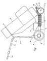
- the golf cart shown in the drawing consists of essentially from a chassis 10, a drive unit 12 and a steering device 14.
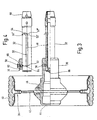
- the chassis 10 comprises a rear chassis part 16, one Longitudinal center piece 18 and a front part 20 existing elongated chassis 22, two on the chassis part 16 protruding in the direction of travel, one adjustable in length Telescopic legs 24 forming the telescopic axis and two at the free ends of the telescopic legs 24 attached side wheels 26 and one on the front part 20 of the chassis 22 pivotally arranged as Twin wheel running support wheel 28 (Fig. 2).
- Each of the telescopic legs 24 is through an outer Axle tube 30 and a telescopic axle shaft 32 formed and by a bellows 34 against penetration protected from dirt and water.
- the free ends are to enable disassembly the telescopic shafts 32 via a lockable plug connection 36 releasably connected to the chassis part 16.
- the side wheels 26 a multi-part flatbed rim 38 on the one profiled solid rubber tire 40 is mounted. to is rotationally fixed connection with the telescopic leg 24 a circular rim rim 42 of the flatbed rim 38 through a hub cover 44 penetrating fastening screws on the face of one the wheel hub forming flange 46 of the axle tube 30 rotatably screwed.
- the telescopic legs 24 have a thrust guide 50 to prevent rotation of the axle tube 30 the axle shaft 32.
- This consists of three over the The circumference of the axle shaft 32 arranged raceway grooves 48, which extends over an end point in FIG. 4 52, 52 'marked section of the axle shaft 32 in its extend in the axial direction.
- One of the ends of the slide guide 50 also closes helical guideway over part the circumference of the axle shaft 32 between end points 52 ' and 52 "running rotary guide 54, their function will be explained below.
- Each acts as a rolling element a ball 56 mounted on the axle tube side in the Raceway grooves 48 a.
- a locking mechanism is provided, which from a on the axle tube 30 by means of the retaining screw 58 and spring 60 there is preloaded locking ball 62, each in a correspondingly arranged Locking recess 64,64 'snaps into the casing of the axle tube 32. In this way, the track width of the side wheels 26 by exerting an axial thrust without adjust further aids.
- the for releasable attachment of the telescopic leg 24 provided connector 36 consists of a on the Axle shaft 32 formed tapered end journal 66, the in a complementary bore 68 of an axle receptacle 70 is insertable. Securing the connector is distributed over three in the circumferential direction arranged, guided in radial bores of the front journal 66 Balls 76, which are in the locking position in bores 78 engage the axle holder 70.
- a trigger mechanism is provided, the one inside the axle shaft designed as a hollow shaft 32 guided trigger plunger 80 includes. This owns at its end projecting into the end journal 66 cylindrical thrust piece provided with an annular groove 82 84, which supports the balls 76 radially inwards.
- the trigger plunger 80 is in the locking position on the axle tube side Front end of the axle shaft 32 with an end section 86 over (Fig. 3).
- the end section 86 abuts in the park position of the telescopic leg 24 on the end face to the facing inner surface of the hub cover 44 on.
- the lifting movement can be done by a Torque triggered on the side gear 26, wherein the rotary guide 54 due to its slope for one appropriate stroke implementation ensures.
- the axle mounts 70 are 72.74 via deep groove ball bearings about a common axis of rotation on the chassis part 16 rotatably mounted. Because of the coaxial alignment can the telescopic legs 24 over a common Drive the drive shaft 88, which on their Front ends in each case when the drive shaft rotates 88 in the drive direction blocking freewheel 90 with the facing ends of the axle receptacles 70 connected is. As the drive unit 12 is on the chassis part 16 arranged electric motor 92 is provided, the is fed from a battery 94 and via a transmission 96 and a belt drive, not shown, with the Drive shaft 88 is coupled.
- front connector 100 of the extension rods 98 rigidly connected front part 20 of the Chassis 22 has a pivot bearing 108 in which an elbow guiding the front wheel 28 as an impeller 110 is pivotable.
- the swivel axis intersects one Footprint 112 in the direction of travel before the contact point of the front wheel 28, which makes the straight running is automatically stabilized.
- the steering device 14 consists of one Folding hinge 114 foldable, against the direction of travel angled drawbar-like handlebar 116, which rigidly connected to the Chassis part 16 of the chassis 22 is connectable and which has a rotary handle 120 for motor control at its free end having.
- the Pocket bottom on the front part 20 of the chassis 22 is supported.
- One attached to handlebar 116 Bracket 124 engages around the top pocket section and ensures a favorable for the removal of the golf clubs Inclination of the golf bag 122.
- the dolly for other goods to be used advantageously, for example for small loads in production facilities.
Landscapes
- Engineering & Computer Science (AREA)
- Mechanical Engineering (AREA)
- Chemical & Material Sciences (AREA)
- Combustion & Propulsion (AREA)
- Transportation (AREA)
- Handcart (AREA)
Description
- Fig. 1
- einen Golfwagen mit einer daran befestigten Golftasche in einer Seitenansicht;
- Fig. 2
- das Fahrwerk des Golfwagens nach Fig. 1 in einer teilweise geschnittenen Draufsicht;
- Fig. 3
- eine Schnittdarstellung eines Teleskopschenkels des Fahrwerks nach Fig. 2;
- Fig. 4
- eine Teleskopwelle des Teleskopschenkels nach Fig. 3 in einer um 90° gedrehten Lage, und
- Fig. 5
- einen vergrößerten Ausschnitt der fahrgestellseitigen Lagerung des Teleskopschenkels nach Fig. 3.
Claims (21)
- Transportwagen für Kleinlasten, insbesondere Golfwagen, mit einem ein insbesondere langgestrecktes Fahrgestell (22) und zwei an den quer zur Fahrtrichtung weisenden Längsseiten des Fahrgestells (22) gleichachsig angeordnete, vorzugsweise angetriebene Seitenräder (26) aufweisenden Fahrwerk (10) und einer an ihren freien Enden die Seitenräder (26) tragenden, unter Änderung von deren Spurweite teleskopisch längenverstellbaren Teleskopachse (24), die zwei an den Längsseiten des Fahrgestells (22) quer abstehende, jeweils eines der Seitenräder (26) führende Teleskopschenkel (24) aufweist, dadurch gekennzeichnet, daß die Teleskopschenkel (24) über eine verrastbare Steckverbindung (36) lösbar mit dem Fahrgestell (22) verbindbar sind.
- Transportwagen nach Anspruch 1, dadurch gekennzeichnet, daß die Teleskopschenkel (24) durch ein äußeres Achsrohr (30) und eine in das Achsrohr eintauchende, fahrgestellseitig gelagerte Achswelle (32) gebildet sind.
- Transportwagen nach Anspruch 2, dadurch gekennzeichnet, daß das Achsrohr (30) ein die Radnabe bildendes Flanschstück (46) aufweist, an dessen Stirnseite das Seitenrad (26) drehfest angeschraubt ist.
- Transportwagen nach Anspruch 2 oder 3, gekennzeichnet durch Mittel (50) zur drehfesten Verbindung des Achsrohrs (30) und der Achswelle (32) der Teleskopschenkel (24) zumindest in einer fahrgestellfernen Fahrstellung und einer fahrgestellnahen Parkstellung der Seitenräder (26).
- Transportwagen nach einem der Ansprüche 1 bis 4, dadurch gekennzeichnet, daß die Teleskopachse (24) eine axial verlaufende Schubführung (50) aufweist.
- Transportwagen nach Anspruch 5, dadurch gekennzeichnet, daß die als Wälzführung ausgeführte Schubführung (50) durch mehrere, vorzugsweise drei über den Umfang der Achswelle (32) verteilte Laufbahnrillen (48) und jeweils einen achsrohrseitig gelagerten, vorzugsweise als Kugel ausgebildeten Wälzkörper (56) gebildet ist.
- Transportwagen nach Anspruch 5, dadurch gekennzeichnet, daß die Schubführung (50) eine längs der Achswelle (32) verlaufende Führungsnut und einen in der Führungsnut geführten, mit dem Achsrohr (30) fest verbundenen Gleitstein aufweist.
- Transportwagen nach einem der Ansprüche 1 bis 7, gekennzeichnet durch eine Sperrvorrichtung (62,64,64'), insbesondere ein Rastgesperre zur Sicherung einer fahrgestellfernen Fahrstellung und einer fahrgestellnahen Parkstellung der Seitenräder (26). 8
- Transportwagen nach Anspruch 8, dadurch gekennzeichnet, daß die Sperrvorrichtung eine an dem Achsrohr (30) gefedert gelagerte, vorzugsweise über eine Halteschraube (58) abgestützte Rastkugel (62) aufweist, welche in der Fahr- und Parkstellung in jeweils eine entsprechend angeordnete Rastausnehmung (64,64') im Mantel der Achswelle (32) selbsttätig einrastet.
- Transportwagen nach einem der Ansprüche 2 bis 9, dadurch gekennzeichnet, daß die Achswellen (32) einen kegeligen Stirnzapfen (66) aufweisen, der in eine kegelige Bohrung (68) einer an dem Fahrgestell (22) vorzugsweise über Rillenkugellager (72,74) drehbar gelagerten Achsaufnahme (70) einsteckbar ist.
- Transportwagen nach einem der Ansprüche 2 bis 10, dadurch gekennzeichnet, daß die Achswellen (32) fahrgestellseitig einrastbare Rastmittel (76) und einen Auslösemechanismus (80,84) zum Auslösen der Rastmittel aus ihrer Raststellung aufweisen.
- Transportwagen nach Anspruch 11, dadurch gekennzeichnet, daß die Achswellen als Hohlwellen (32) ausgebildet sind, und daß der Auslösemechanismus einen im Inneren der Hohlwelle (32) geführten Auslösestößel (80) aufweist, der durch Verschiebung des Achsrohres (30) in eine Hubbewegung versetzbar ist und dabei auf die Rastmittel (76) einwirkt.
- Transportwagen nach einem der Ansprüche 4 bis 12, gekennzeichnet durch eine an das fahrgestellnahe Ende der Schubführung (50) anschließende, schraubenlinienförmig über einen Teil des Umfangs der Achswelle (32) verlaufende Drehführung (54), und einen bei Bewegung des Achsrohres (30) entlang der Drehführung (54) den Auslösestößel (80) in eine Hubbewegung versetzenden Anschlag (44).
- Transportwagen nach Anspruch 12 oder 13, dadurch gekennzeichnet, daß der Auslösestößel (80) an seinem in den Stirnzapfen (66) eingreifenden Ende ein mit einer Ringnut (82) versehenes zylindrisches Druckstück (84) aufweist, das mindestens eine den Mantel des Stirnzapfens (66) durchgreifende, als Rastmittel bestimmte Kugel (76) in Abhängigkeit von der Hublage des Auslösestößels (80) mit einer Nutflanke oder dem Nutgrund der Ringnut (82) radial abstützt.
- Transportwagen nach einem der Ansprüche 1 bis 14, dadurch gekennzeichnet, daß die mit gemeinsamer Drehachse angeordneten Teleskopschenkel (24) über jeweils einen Freilauf (90) mit den freien Enden einer gemeinsamen Antriebswelle (88) verbunden sind.
- Transportwagen nach Anspruch 15, dadurch gekennzeichnet, daß auf dem Fahrgestell (22) ein vorzugsweise über einen Riementrieb mit der Antriebswelle (88) gekoppelter, aus einer Batterie (94) gespeister Elektromotor (92) angeordnet ist.
- Transportwagen nach einem der Ansprüche 1 bis 16, dadurch gekennzeichnet, daß das Fahrwerk (10) ein in Fahrtrichtung im Abstand vorzugsweise vor den Seitenrädern (26) angeordnetes, insbesondere als Zwillingsrad ausgebildetes Stützrad (28) aufweist.
- Transportwagen nach Anspruch 17, dadurch gekennzeichnet, daß das Stützrad (28) als Führungsrad unter Einhaltung eines Nachlaufs frei schwenkbar an einem Vorderteil (20) des Fahrgestells (22) aufgehängt ist.
- Transportwagen nach Anspruch 17 oder 18, gekennzeichnet durch mindestens eine, vorzugsweise zwei zueinander parallele Verlängerungsstangen (98), die ein Längsmittelstück des Fahrgestells (22) bilden und unter Verkürzung des Radstandes in ein die Teleskopschenkel (24) tragendes hinteres Chassisteil (16) des Fahrgestells (22) einschiebbar sind.
- Transportwagen nach einem der Ansprüche 1 bis 19, gekennzeichnet durch eine mit dem Fahrgestell (22) lösbar starr verbindbare, teilbar oder faltbare deichselartige Lenkvorrichtung (14).
- Transportwagen nach Anspruch 20, dadurch gekennzeichnet, daß an der Lenkvorrichtung (14) eine Halterung (124) für eine Golftasche (122) angeordnet ist.
Applications Claiming Priority (3)
| Application Number | Priority Date | Filing Date | Title |
|---|---|---|---|
| DE19714374 | 1997-04-08 | ||
| DE19714374 | 1997-04-08 | ||
| PCT/EP1998/002047 WO1998045154A1 (de) | 1997-04-08 | 1998-04-08 | Transportwagen für kleinlasten, insbesondere golfwagen |
Publications (2)
| Publication Number | Publication Date |
|---|---|
| EP1131237A1 EP1131237A1 (de) | 2001-09-12 |
| EP1131237B1 true EP1131237B1 (de) | 2003-07-02 |
Family
ID=7825728
Family Applications (1)
| Application Number | Title | Priority Date | Filing Date |
|---|---|---|---|
| EP98922668A Expired - Lifetime EP1131237B1 (de) | 1997-04-08 | 1998-04-08 | Transportwagen für kleinlasten, insbesondere golfwagen |
Country Status (4)
| Country | Link |
|---|---|
| EP (1) | EP1131237B1 (de) |
| AT (1) | ATE244176T1 (de) |
| DE (2) | DE19815813A1 (de) |
| WO (1) | WO1998045154A1 (de) |
Families Citing this family (9)
| Publication number | Priority date | Publication date | Assignee | Title |
|---|---|---|---|---|
| DE20305294U1 (de) | 2003-04-01 | 2003-08-14 | Hupfer Metallwerke Gmbh & Co, 48653 Coesfeld | Transportwagen mit lenkbeweglichen, lenkfixierbaren Laufrollen |
| US20140107868A1 (en) * | 2012-10-15 | 2014-04-17 | Mirko DiGiacomcantonio | Self-propelled luggage |
| DK179047B1 (en) * | 2015-07-10 | 2017-09-18 | Carryon Golftrolley Aps | Golf cart cabin- |
| CA2997160C (en) | 2015-10-16 | 2023-10-03 | Lemmings LLC | Robotic golf caddy |
| US10197999B2 (en) | 2015-10-16 | 2019-02-05 | Lemmings, Llc | Robotic golf caddy |
| CN206499832U (zh) | 2016-12-31 | 2017-09-19 | 广州宝名机电有限公司 | 一种高尔夫球袋手推车及其驱动组件 |
| EP3651998A4 (de) | 2017-07-12 | 2021-03-31 | AxleTech International IP Holdings, LLC | Einstellbare achsanordnung für ein fahrzeug |
| CN112706817B (zh) * | 2021-01-26 | 2022-03-11 | 衢州学院 | 一种方便安装且稳定的购物车万向轮 |
| US20250262893A1 (en) * | 2024-02-15 | 2025-08-21 | Honda Motor Co., Ltd. | Removable wheel assembly and method |
Family Cites Families (5)
| Publication number | Priority date | Publication date | Assignee | Title |
|---|---|---|---|---|
| US4570731A (en) * | 1983-09-09 | 1986-02-18 | Del Oaks | Controllable golf bag cart |
| FR2597036B1 (fr) * | 1986-04-11 | 1991-04-12 | Laguilharre Pierre | Groupe moto-propulseur pour vehicule porteur de charge tel que chariot de golf et vehicule porteur de charge equipe de ce groupe moto-propulseur |
| US4681341A (en) * | 1986-07-14 | 1987-07-21 | Winston Lai | Collapsible golf cart with one-step folding operation |
| US4834409A (en) * | 1987-10-13 | 1989-05-30 | Kramer Duwayne E | Personal mobility vehicle with expansible wheel base and wheel track |
| DE4407627C2 (de) * | 1994-03-08 | 1996-04-18 | Wolfgang Will | Golfwagen |
-
1998
- 1998-04-08 DE DE19815813A patent/DE19815813A1/de not_active Withdrawn
- 1998-04-08 WO PCT/EP1998/002047 patent/WO1998045154A1/de not_active Ceased
- 1998-04-08 AT AT98922668T patent/ATE244176T1/de not_active IP Right Cessation
- 1998-04-08 EP EP98922668A patent/EP1131237B1/de not_active Expired - Lifetime
- 1998-04-08 DE DE59808932T patent/DE59808932D1/de not_active Expired - Fee Related
Also Published As
| Publication number | Publication date |
|---|---|
| WO1998045154A1 (de) | 1998-10-15 |
| EP1131237A1 (de) | 2001-09-12 |
| DE59808932D1 (de) | 2003-08-07 |
| ATE244176T1 (de) | 2003-07-15 |
| DE19815813A1 (de) | 1998-10-15 |
Similar Documents
| Publication | Publication Date | Title |
|---|---|---|
| DE69119237T2 (de) | Kraftfahrzeug | |
| DE3918001C2 (de) | Behindertenfahrzeug mit einem zweiteiligen Grundrahmen | |
| DE69016255T2 (de) | Motorisierter Rollstuhl. | |
| EP3145800B1 (de) | Einspuriger tretroller | |
| EP1267657A1 (de) | Gepäckstück mit rollen | |
| DE19534974A1 (de) | Zusammenlegbare Karre | |
| DE4237558A1 (de) | ||
| EP2954938A1 (de) | Klappbarer trettroller mit gepäckträger | |
| WO2014009143A1 (de) | Motorisiertes dreirädriges golf-trolley | |
| EP1131237B1 (de) | Transportwagen für kleinlasten, insbesondere golfwagen | |
| DE3511461A1 (de) | Golfwagen mit batteriebetriebenem hilfsantrieb | |
| DE202017102137U1 (de) | Fahrbare Gehhilfe | |
| WO2004031016A1 (de) | Trolley mit einem motorisch antreibbaren laufwerk | |
| DE10158201B4 (de) | Elektrisch angetriebenes Kleinfahrzeug | |
| DE29503741U1 (de) | Golfwagen | |
| DE102008019688A1 (de) | Fahrzeug zum Überwinden von Stufen | |
| EP4426598B1 (de) | Fahrzeug mit einer antriebseinheit und einer damit lösbar verbindbaren applikation | |
| EP2724914B1 (de) | Vorrichtung zum Befördern von Gütern und/oder einer Person | |
| DE102022124205B3 (de) | Zusammenfaltbares Fahrzeug sowie System aus einem derartigen Fahrzeug und einer Tasche | |
| EP1448073A1 (de) | Transportvorrichtung für gepäckstücke od.dgl. | |
| EP2623391A2 (de) | Transportgerät zum Transport einer Golftasche und wenigstens einer Person | |
| DE3840114A1 (de) | Sturzkonstante radaufhaengung | |
| DE102020119267A1 (de) | Fahrwerk für einen Schubwagen und Schubwagen | |
| DE3110687A1 (de) | Rollstuhl | |
| DE4232464A1 (de) | Fahrbares Rollengestell für Fahrräder und Mofas |
Legal Events
| Date | Code | Title | Description |
|---|---|---|---|
| PUAI | Public reference made under article 153(3) epc to a published international application that has entered the european phase |
Free format text: ORIGINAL CODE: 0009012 |
|
| 17P | Request for examination filed |
Effective date: 19991228 |
|
| AK | Designated contracting states |
Kind code of ref document: A1 Designated state(s): AT CH DE FR GB IE IT LI |
|
| GRAH | Despatch of communication of intention to grant a patent |
Free format text: ORIGINAL CODE: EPIDOS IGRA |
|
| GRAH | Despatch of communication of intention to grant a patent |
Free format text: ORIGINAL CODE: EPIDOS IGRA |
|
| RAP1 | Party data changed (applicant data changed or rights of an application transferred) |
Owner name: WEBER, GERHARD |
|
| RIN1 | Information on inventor provided before grant (corrected) |
Inventor name: WEBER, GERHARD |
|
| GRAA | (expected) grant |
Free format text: ORIGINAL CODE: 0009210 |
|
| AK | Designated contracting states |
Designated state(s): AT CH DE FR GB IE IT LI |
|
| PG25 | Lapsed in a contracting state [announced via postgrant information from national office to epo] |
Ref country code: IT Free format text: LAPSE BECAUSE OF FAILURE TO SUBMIT A TRANSLATION OF THE DESCRIPTION OR TO PAY THE FEE WITHIN THE PRESCRIBED TIME-LIMIT;WARNING: LAPSES OF ITALIAN PATENTS WITH EFFECTIVE DATE BEFORE 2007 MAY HAVE OCCURRED AT ANY TIME BEFORE 2007. THE CORRECT EFFECTIVE DATE MAY BE DIFFERENT FROM THE ONE RECORDED. Effective date: 20030702 Ref country code: IE Free format text: LAPSE BECAUSE OF FAILURE TO SUBMIT A TRANSLATION OF THE DESCRIPTION OR TO PAY THE FEE WITHIN THE PRESCRIBED TIME-LIMIT Effective date: 20030702 |
|
| REG | Reference to a national code |
Ref country code: GB Ref legal event code: FG4D Free format text: NOT ENGLISH |
|
| REG | Reference to a national code |
Ref country code: CH Ref legal event code: EP |
|
| REG | Reference to a national code |
Ref country code: IE Ref legal event code: FG4D Free format text: GERMAN |
|
| REF | Corresponds to: |
Ref document number: 59808932 Country of ref document: DE Date of ref document: 20030807 Kind code of ref document: P |
|
| GBT | Gb: translation of ep patent filed (gb section 77(6)(a)/1977) |
Effective date: 20031105 |
|
| REG | Reference to a national code |
Ref country code: IE Ref legal event code: FD4D |
|
| PG25 | Lapsed in a contracting state [announced via postgrant information from national office to epo] |
Ref country code: GB Free format text: LAPSE BECAUSE OF NON-PAYMENT OF DUE FEES Effective date: 20040408 |
|
| ET | Fr: translation filed | ||
| PLBE | No opposition filed within time limit |
Free format text: ORIGINAL CODE: 0009261 |
|
| STAA | Information on the status of an ep patent application or granted ep patent |
Free format text: STATUS: NO OPPOSITION FILED WITHIN TIME LIMIT |
|
| 26N | No opposition filed |
Effective date: 20040405 |
|
| PGFP | Annual fee paid to national office [announced via postgrant information from national office to epo] |
Ref country code: DE Payment date: 20040924 Year of fee payment: 7 |
|
| PGFP | Annual fee paid to national office [announced via postgrant information from national office to epo] |
Ref country code: AT Payment date: 20041007 Year of fee payment: 7 |
|
| PGFP | Annual fee paid to national office [announced via postgrant information from national office to epo] |
Ref country code: FR Payment date: 20041010 Year of fee payment: 7 |
|
| PGFP | Annual fee paid to national office [announced via postgrant information from national office to epo] |
Ref country code: CH Payment date: 20041018 Year of fee payment: 7 |
|
| GBPC | Gb: european patent ceased through non-payment of renewal fee |
Effective date: 20040408 |
|
| PG25 | Lapsed in a contracting state [announced via postgrant information from national office to epo] |
Ref country code: AT Free format text: LAPSE BECAUSE OF NON-PAYMENT OF DUE FEES Effective date: 20050408 |
|
| PG25 | Lapsed in a contracting state [announced via postgrant information from national office to epo] |
Ref country code: LI Free format text: LAPSE BECAUSE OF NON-PAYMENT OF DUE FEES Effective date: 20050430 Ref country code: CH Free format text: LAPSE BECAUSE OF NON-PAYMENT OF DUE FEES Effective date: 20050430 |
|
| PG25 | Lapsed in a contracting state [announced via postgrant information from national office to epo] |
Ref country code: DE Free format text: LAPSE BECAUSE OF NON-PAYMENT OF DUE FEES Effective date: 20051101 |
|
| REG | Reference to a national code |
Ref country code: CH Ref legal event code: PL |
|
| PG25 | Lapsed in a contracting state [announced via postgrant information from national office to epo] |
Ref country code: FR Free format text: LAPSE BECAUSE OF NON-PAYMENT OF DUE FEES Effective date: 20051230 |
|
| REG | Reference to a national code |
Ref country code: FR Ref legal event code: ST Effective date: 20051230 |