EP1130828B1 - Optical transmission system with dispersion compensation - Google Patents
Optical transmission system with dispersion compensation Download PDFInfo
- Publication number
- EP1130828B1 EP1130828B1 EP01102716A EP01102716A EP1130828B1 EP 1130828 B1 EP1130828 B1 EP 1130828B1 EP 01102716 A EP01102716 A EP 01102716A EP 01102716 A EP01102716 A EP 01102716A EP 1130828 B1 EP1130828 B1 EP 1130828B1
- Authority
- EP
- European Patent Office
- Prior art keywords
- dispersion
- optical transmission
- fiber
- optical
- wavelength
- Prior art date
- Legal status (The legal status is an assumption and is not a legal conclusion. Google has not performed a legal analysis and makes no representation as to the accuracy of the status listed.)
- Expired - Lifetime
Links
- 239000006185 dispersion Substances 0.000 title claims description 134
- 230000003287 optical effect Effects 0.000 title claims description 85
- 230000005540 biological transmission Effects 0.000 title claims description 82
- 239000013307 optical fiber Substances 0.000 claims description 53
- 239000000835 fiber Substances 0.000 claims description 43
- 230000008054 signal transmission Effects 0.000 claims description 2
- 230000000052 comparative effect Effects 0.000 description 10
- 230000001186 cumulative effect Effects 0.000 description 9
- 238000004891 communication Methods 0.000 description 4
- 238000012423 maintenance Methods 0.000 description 3
- VYPSYNLAJGMNEJ-UHFFFAOYSA-N Silicium dioxide Chemical compound O=[Si]=O VYPSYNLAJGMNEJ-UHFFFAOYSA-N 0.000 description 2
- 238000009434 installation Methods 0.000 description 2
- 238000000034 method Methods 0.000 description 2
- AFCARXCZXQIEQB-UHFFFAOYSA-N N-[3-oxo-3-(2,4,6,7-tetrahydrotriazolo[4,5-c]pyridin-5-yl)propyl]-2-[[3-(trifluoromethoxy)phenyl]methylamino]pyrimidine-5-carboxamide Chemical compound O=C(CCNC(=O)C=1C=NC(=NC=1)NCC1=CC(=CC=C1)OC(F)(F)F)N1CC2=C(CC1)NN=N2 AFCARXCZXQIEQB-UHFFFAOYSA-N 0.000 description 1
- 230000015556 catabolic process Effects 0.000 description 1
- 230000003247 decreasing effect Effects 0.000 description 1
- 238000006731 degradation reaction Methods 0.000 description 1
- 238000013461 design Methods 0.000 description 1
- 230000006866 deterioration Effects 0.000 description 1
- 238000010586 diagram Methods 0.000 description 1
- 238000005516 engineering process Methods 0.000 description 1
- 238000002474 experimental method Methods 0.000 description 1
- 239000011521 glass Substances 0.000 description 1
- 239000000377 silicon dioxide Substances 0.000 description 1
Images

Classifications
-
- H—ELECTRICITY
- H04—ELECTRIC COMMUNICATION TECHNIQUE
- H04B—TRANSMISSION
- H04B10/00—Transmission systems employing electromagnetic waves other than radio-waves, e.g. infrared, visible or ultraviolet light, or employing corpuscular radiation, e.g. quantum communication
- H04B10/25—Arrangements specific to fibre transmission
- H04B10/2507—Arrangements specific to fibre transmission for the reduction or elimination of distortion or dispersion
- H04B10/2513—Arrangements specific to fibre transmission for the reduction or elimination of distortion or dispersion due to chromatic dispersion
- H04B10/2525—Arrangements specific to fibre transmission for the reduction or elimination of distortion or dispersion due to chromatic dispersion using dispersion-compensating fibres
- H04B10/25253—Arrangements specific to fibre transmission for the reduction or elimination of distortion or dispersion due to chromatic dispersion using dispersion-compensating fibres with dispersion management, i.e. using a combination of different kind of fibres in the transmission system
Definitions
- the present invention relates to an optical transmission line that transmits signal light, and to an optical transmission system having the optical transmission line.
- an optical transmission system it is desirable to lessen the absolute value of cumulative chromatic dispersion of the optical transmission line at a signal light wavelength in order to restrain the waveform degradation of the signal light.
- WDM Wavelength Division Multiplexing
- the absolute value of cumulative chromatic dispersion of the optical transmission line be small in a wide wavelength range so that optical communication can be performed in a volume as large as possible by multiplexing the signal light as much as possible. Therefore, generally by connecting various kinds of optical fibers or by providing a dispersion compensation module to compensate for the dispersion of an optical fiber, the absolute value of the cumulative chromatic dispersion is made small in a wide wavelength range.
- Literature 1 M. Murakami, et al., "Long-haul 16x10 WDM Transmission Experiment Using Higher Order Fiber Dispersion Management Technique", ECOC'98, pp.313 - 314 (1998 ) as well as Literature 2: F. M. Madani, et al, "Performance Limit of Long-distance WDM Dispersion-managed Transmission System Using Higher Order Dispersion Compensation Fibers", IEEE Photon. Technol. Lett., Vol.11, No.5, pp.
- the absolute value of cumulative chromatic dispersion is made small by connecting a standard 1.3 ⁇ m band zero dispersion optical fiber which has a zero dispersion wavelength near the 1310 nm wavelength, and in which both the chromatic dispersion and the dispersion slope are positive at the 1550 nm wavelength, with a dispersion compensating optical fiber in which both the chromatic dispersion and the dispersion slope are negative at the 1550 nm wavelength.
- the dispersion compensating optical fiber is, in some cases, installed in a relay section together with the 1.3 ⁇ m band zero dispersion optical fiber, and in other cases, it is rolled up in a coil as a dispersion compensation module to be put in a repeater or a receiver.
- Literature 3 Y. Yokoyama, et al., "Practically Feasible Dispersion Flattened Fibers Produced by VAD Technique", ECOC'98, pp.131-132 (1998 ) discloses a positive dispersion optical fiber and a negative dispersion optical fiber: the former has a positive chromatic dispersion and a small absolute value of dispersion slope at the 1550 nm wavelength, whereas in the latter the chromatic dispersion is negative and the absolute value of the dispersion slope is small. When these two optical fibers are connected, the absolute value of cumulative chromatic dispersion of the optical transmission line diminishes in a wide wavelength range.
- the installation and maintenance are easy.
- the transmission loss of the dispersion compensating optical fiber used in the dispersion compensation module is greater than that of other optical fibers.
- the longer the length of the 1.3 ⁇ m band zero dispersion optical fiber the longer the dispersion compensating optical fiber must be in the dispersion compensation module. Accordingly, the transmission loss of the optical transmission line becomes greater as a whole.
- US 5995694 discloses a wavelength division multiplex communication link for optical transmissions, which is able to provide a ultra high bit-rate wavelength division multiplex communication at a 1550 nm wavelength band using the existing 1300 nm band zero dispersion of a single mode fiber network.
- a dispersion compensating fiber DCF having a negative dispersion value at a 1550 nm wavelength band is connected to a single mode fiber SMF of the existing 1300 nm band zero dispersion of a single mode fiber network with a line length which compensates the dispersion slope of the single mode fiber to zero.
- a dispersion flat fiber which makes the dispersion slope zero is further connected, with a line length which makes the remaining dispersion value zero, to the terminal end of a connection link of the single mode fiber SMF and dispersion compensating fiber DCF, whereby both the dispersion slope of a single mode fiber and dispersion value thereof can be adjusted to be zero at the terminal end of the dispersion flat fiber DFF.
- an optical transmission line comprising: a relay section comprised by an optical transmission fiber for transmission of signal light between a transmitter and a receiver, and at least one repeater coupled to the optical transmission fiber, characterized in that: the optical transmission fiber has a chromatic dispersion of +4 to +10 ps ⁇ nm -1 ⁇ km -1 and a dispersion slope of 0 to +0.04 ps ⁇ nm-2 ⁇ km -1 at the 1550 nm wavelength that: the at least one repeater includes a module comprising a coil of dispersion compensating optical fiber having a chromatic dispersion of -40 ps ⁇ nm -1 ⁇ km -1 or less and a dispersion slope of -0.10 ps ⁇ nm -2 ⁇ km -1 or less at the 1550 nm wavelength, for the compensation of chromatic dispersion in the signal light generated during transmission in the optical transmission fiber, and wherein said dispersion compensating optical fiber has a length that is sufficient
- An optical transmission system is also provided, which incorporates the optical transmission line, a transmitter and a receiver.
- the optical transmission fiber has a dispersion slope of +0.01 to +0.03 ps ⁇ nm -2 ⁇ km -1 , and an effective area equal to or more than 45 ⁇ m 2 .
- the dispersion compensating optical fiber may have a chromatic dispersion of -80 ps ⁇ nm -1 ⁇ km -1 or less, more preferably, -100 ps ⁇ nm -1 ⁇ km -1 or less, and a dispersion slope of -0.20 ps ⁇ nm -2 ⁇ km -1 or less.
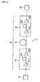
- the optical transmission system 1 shown in Figure 1 is equipped, as an optical transmission line 2, with a repeater 31, an optical transmission fiber 41, and a repeater 32, at least in a part of the transmission path of signal light that extends from a transmitter 10 to a receiver 20.
- the repeater 31 comprises an optical amplifier 311, a dispersion compensating optical fiber 313, and an optical amplifier 312.
- the repeater 32 has an optical amplifier 321, a dispersion compensating optical fiber 323, and an optical amplifier 322.
- the transmitter 10 sends out signal light of plural wavelengths in the 1.55 ⁇ m wavelength band after multiplexing the wavelengths.
- the signal light propagates the optical transmission line 2 to the receiver 20.
- the receiver 20 receives the signal light, demultiplexing it to each wavelength.
- the optical transmission fiber 41 exhibits a chromatic dispersion of +4 to +10 ps ⁇ nm -1 ⁇ km -1 , and a dispersion slope of 0 to +0.04 ps ⁇ nm -2 ⁇ km -1 at the 1550 nm wavelength. It is installed in the relay section from the repeater 31 to the repeater 32.
- Each of the dispersion compensating optical fibers 313, 323 has a chromatic dispersion of -40 ps ⁇ nm -1 ⁇ km -1 or less at the 1550 nm wavelength, and a dispersion slope of -0.10 ps ⁇ nm -2 ⁇ km -1 or less. It is rolled up in a coil as a module to be provided within the repeaters 31, 32.
- the optical transmission fiber 41 and the dispersion compensating optical fibers, 313, 323 are made of silica-based glass, and it is possible to design and produce a refractive index profile appropriately so as to give the above-mentioned characteristics of chromatic dispersion and dispersion slope, respectively.
- Each of the optical amplifiers 311, 312, 321, and 322 amplifies the signal light of plural wavelengths altogether.
- An amplifier using an Er-doped optical fiber in which Er element is added to the light path region is preferable.
- the optical amplifier 311 is positioned in the first part of the dispersion compensating optical fiber 313 in the repeater 31, and the optical amplifier 312 is provided in the latter part of the dispersion compensating optical fiber 313.
- the optical amplifier 321 is positioned in the first part of the compensating optical fiber 323 in the repeater 32, and the optical amplifier 322 is provided in the latter part of the dispersion compensating optical fiber 323.
- the sign of the chromatic dispersion of the optical transmission fiber 41 and that of each of the dispersion compensating optical fibers 313, 323 differ from each other.
- the sign of the chromatic dispersion slope of optical transmission fiber 41 and that of each of the dispersion compensating optical fibers 313, 323 are different from each other. Consequently, the absolute value of cumulative chromatic dispersion of the optical transmission line 2 can be made small in a wide wavelength range by setting an appropriate ratio between the length of the optical transmission fiber 41 and each length of the dispersion compensating optical fibers 313, 323. Therefore, a broad bandwidth WDM transmission as well as a high bit rate transmission becomes possible.
- the optical transmission fiber 41 exhibit a dispersion slope of +0.01 to +0.03 ps ⁇ nm -2 ⁇ km -1 at the 1550 nm wavelength.
- the length of the dispersion compensating optical fibers 313, 323 that is necessary for compensating the chromatic dispersion and the dispersion slope can be short because the chromatic dispersion and the dispersion slope of the optical transmission fiber 41 are small at the 1550 nm wavelength. Therefore, the loss of signal light in the dispersion compensating optical fibers 313, 323 is small. Accordingly, the loss of signal light in the optical transmission line 2 is also small as a whole.
- the dispersion compensating optical fibers 313, 323 preferably have a chromatic dispersion of -80 ps ⁇ nm -1 ⁇ km -1 or less, and a dispersion slope of -0.20 ps ⁇ nm -2 ⁇ km -1 or less at the 1550 nm wavelength, and more preferably, a chromatic dispersion of -100 ps ⁇ nm -1 ⁇ km -1 or less at the 1550 nm wavelength.
- the optical transmission fiber 41 preferably has an effective area equal to or more than 45 ⁇ m 2 in the 1550 nm wavelength.
- this dispersion compensation module is easy because the dispersion compensating optical fibers 313, 323 are not laid but are rolled up in a coil as a module and are provided inside the repeaters 31, 32.
- the optical transmission fiber has a length of 80 km, and the dispersion compensating optical fiber has a length that is sufficient to compensate the chromatic dispersion of the optical transmission fiber at the 1550 nm wavelength.
- the optical transmission fiber of the comparative example is a 1.3 ⁇ m band zero dispersion optical fiber. Each characteristic is a value at 1550 nm.
- each implementation example is as follows.
- the length of the dispersion compensating optical fibers the comparative example is 12.4 km, whereas that of each implementation examples 1 and 2 is 4.2 km, and implementation examples 3 and 4 is 8.7 km, respectively; thus, each implementation example is shorter than the comparative example.
- the comparative example is 7.6 dB, whereas that of each implementation examples 1 and 2 is 2.6 dB, and that of each implementation examples 3 and 4 is 2.8 dB; thus, each implementation example is smaller than the comparative example by about 5 dB. Therefore, in each implementation example, the S/N ratio improves by about 5 dB as compared with the comparative example. Also, it is possible to restrain the occurrence of the nonlinear optical phenomenon by decreasing the power of signal light because the deterioration of the S/N ratio of signal light in the dispersion compensating optical fiber is small.
- a comparison between implementation examples 1 and 2, and implementation examples 3 and 4, show that as to the length of the dispersion compensating optical fiber the former is 4.2 km, and the latter is 8.7 km, whereas they are almost the same with respect to the loss of signal light in the dispersion compensating optical fibers. This is because the latter is smaller than the former with respect to the transmission loss of the dispersion compensating optical fibers per unit length.
- the average chromatic dispersion of the whole optical transmission line in which an optical transmission fiber and a dispersion compensating optical fiber are connected is zero at the 1550 nm wavelength in each implementation example.
- the average dispersion slope of the whole optical transmission line in which an optical transmission fiber and a dispersion compensating optical fiber are connected is small at the 1550 nm wavelength in each implementation example. Consequently, the absolute value of cumulative chromatic dispersion of the optical transmission line is small in a broad bandwidth in each implementation example, and broad bandwidth WDM transmission and high bit rate transmission are possible.
Landscapes
- Physics & Mathematics (AREA)
- Electromagnetism (AREA)
- Engineering & Computer Science (AREA)
- Computer Networks & Wireless Communication (AREA)
- Signal Processing (AREA)
- Optical Communication System (AREA)
- Optical Fibers, Optical Fiber Cores, And Optical Fiber Bundles (AREA)
Applications Claiming Priority (2)
| Application Number | Priority Date | Filing Date | Title |
|---|---|---|---|
| JP2000029230A JP2001215346A (ja) | 2000-02-07 | 2000-02-07 | 光伝送路および光伝送システム |
| JP2000029230 | 2000-02-07 |
Publications (3)
| Publication Number | Publication Date |
|---|---|
| EP1130828A2 EP1130828A2 (en) | 2001-09-05 |
| EP1130828A3 EP1130828A3 (en) | 2004-09-29 |
| EP1130828B1 true EP1130828B1 (en) | 2011-08-03 |
Family
ID=18554520
Family Applications (1)
| Application Number | Title | Priority Date | Filing Date |
|---|---|---|---|
| EP01102716A Expired - Lifetime EP1130828B1 (en) | 2000-02-07 | 2001-02-06 | Optical transmission system with dispersion compensation |
Country Status (3)
| Country | Link |
|---|---|
| US (1) | US6865326B2 (enExample) |
| EP (1) | EP1130828B1 (enExample) |
| JP (1) | JP2001215346A (enExample) |
Families Citing this family (6)
| Publication number | Priority date | Publication date | Assignee | Title |
|---|---|---|---|---|
| WO2003001257A1 (en) * | 2001-04-12 | 2003-01-03 | Corning Incorporated | Dispersion managed cable for wdm systems |
| JP2003066262A (ja) * | 2001-08-29 | 2003-03-05 | Sumitomo Electric Ind Ltd | 光伝送路および光通信システム |
| JP3937141B2 (ja) * | 2002-02-01 | 2007-06-27 | 日本電気株式会社 | 波長分割多重光伝送システム、及び光通信方法 |
| FR2851100B1 (fr) * | 2003-02-07 | 2005-05-27 | France Telecom | Dispositif et procede de transmission optique a tres haut debit, utilisation de ce dispositif et de ce procede |
| KR100786647B1 (ko) * | 2005-03-09 | 2007-12-21 | 한국과학기술연구원 | 광통신 시스템용 가변 분산 및 분산기울기 보상기 |
| US11982833B2 (en) * | 2021-03-30 | 2024-05-14 | Corning Incorporated | Dispersion compensation fiber and dispersion compensation module |
Family Cites Families (5)
| Publication number | Priority date | Publication date | Assignee | Title |
|---|---|---|---|---|
| US5361319A (en) | 1992-02-04 | 1994-11-01 | Corning Incorporated | Dispersion compensating devices and systems |
| GB2299473A (en) | 1995-03-27 | 1996-10-02 | Hitachi Cable | Broadband long-distance optical fibre communications |
| US5995694A (en) * | 1996-06-21 | 1999-11-30 | The Furukawa Electric Co., Ltd. | Wavelength division multiplex communication link for optical transmission |
| US5905838A (en) * | 1998-02-18 | 1999-05-18 | Lucent Technologies Inc. | Dual window WDM optical fiber communication |
| FR2795828B1 (fr) * | 1999-06-29 | 2001-10-05 | Cit Alcatel | Fibre optique pour la compensation de la dispersion chromatique d'une fibre optique a dispersion chromatique positive |
-
2000
- 2000-02-07 JP JP2000029230A patent/JP2001215346A/ja active Pending
-
2001
- 2001-02-06 EP EP01102716A patent/EP1130828B1/en not_active Expired - Lifetime
- 2001-02-06 US US09/776,720 patent/US6865326B2/en not_active Expired - Lifetime
Also Published As
| Publication number | Publication date |
|---|---|
| EP1130828A3 (en) | 2004-09-29 |
| EP1130828A2 (en) | 2001-09-05 |
| US20010017969A1 (en) | 2001-08-30 |
| US6865326B2 (en) | 2005-03-08 |
| JP2001215346A (ja) | 2001-08-10 |
Similar Documents
| Publication | Publication Date | Title |
|---|---|---|
| KR100437750B1 (ko) | 광섬유통신시스템및방법 | |
| EP0903877B1 (en) | Optical fiber dispersion compensation | |
| EP0626768B1 (en) | High capacity optical fiber network and fiber | |
| US7200333B2 (en) | Optical communication apparatus, system, and method that properly compensate for chromatic dispersion | |
| US6684016B2 (en) | Optical fiber for wavelength division multiplexing optical transmission system using densely spaced optical channels | |
| US6681082B1 (en) | Wavelength division multiplexing optical transmission system, optical amplifier and dispersion compensator | |
| AU3194700A (en) | WDM optical communication system | |
| US7164829B2 (en) | Optical fiber, optical transmission line and optical communications system | |
| EP1130828B1 (en) | Optical transmission system with dispersion compensation | |
| US7254342B2 (en) | Method and system for transmitting information in an optical communication system with low signal distortion | |
| US6856738B2 (en) | Optical fiber and optical transmission system | |
| JP4259186B2 (ja) | 光伝送システム | |
| US6778748B2 (en) | Optical fiber, dispersion compensator using the same, and optical transmission system | |
| US20020122646A1 (en) | Optical fiber, and dispersion compensator using same, optical transmission line using same and optical transmission system using same | |
| CA2357234C (en) | Optical amplifier and optical transmission system having one or more fibers with different dispersion characteristics | |
| Mukasa et al. | Dispersion-managed transmission lines with reverse-dispersion fiber | |
| US6823123B2 (en) | Method and apparatus for providing dispersion compensation | |
| US20030044146A1 (en) | Optical transmission line and optical communication system | |
| EP1267504A2 (en) | Optical communication link | |
| AU6480200A (en) | Fiber optic cable for increased transmission capacity and wavelength division multiplexing optical transmission system using the same | |
| US7046433B2 (en) | Optical fiber, and optical module and Raman amplifier using the optical fiber | |
| Yang et al. | Design options for terabits/second WDM systems | |
| SUZUKI et al. | Dispersion managed optical transmission lines and fibers | |
| Izadpanah et al. | System applications of dispersion-compensation techniques in upgrading interoffice 1310 nm-optimized fiber networks | |
| AU753237B2 (en) | Optical telecommunications system |
Legal Events
| Date | Code | Title | Description |
|---|---|---|---|
| PUAI | Public reference made under article 153(3) epc to a published international application that has entered the european phase |
Free format text: ORIGINAL CODE: 0009012 |
|
| AK | Designated contracting states |
Kind code of ref document: A2 Designated state(s): AT BE CH CY DE DK ES FI FR GB GR IE IT LI LU MC NL PT SE TR |
|
| AX | Request for extension of the european patent |
Free format text: AL;LT;LV;MK;RO;SI |
|
| PUAL | Search report despatched |
Free format text: ORIGINAL CODE: 0009013 |
|
| AK | Designated contracting states |
Kind code of ref document: A3 Designated state(s): AT BE CH CY DE DK ES FI FR GB GR IE IT LI LU MC NL PT SE TR |
|
| AX | Request for extension of the european patent |
Extension state: AL LT LV MK RO SI |
|
| 17P | Request for examination filed |
Effective date: 20041110 |
|
| AKX | Designation fees paid |
Designated state(s): DE FR GB IT |
|
| 17Q | First examination report despatched |
Effective date: 20061218 |
|
| GRAP | Despatch of communication of intention to grant a patent |
Free format text: ORIGINAL CODE: EPIDOSNIGR1 |
|
| RTI1 | Title (correction) |
Free format text: OPTICAL TRANSMISSION SYSTEM WITH DISPERSION COMPENSATION |
|
| GRAS | Grant fee paid |
Free format text: ORIGINAL CODE: EPIDOSNIGR3 |
|
| GRAA | (expected) grant |
Free format text: ORIGINAL CODE: 0009210 |
|
| AK | Designated contracting states |
Kind code of ref document: B1 Designated state(s): DE FR GB IT |
|
| REG | Reference to a national code |
Ref country code: GB Ref legal event code: FG4D |
|
| REG | Reference to a national code |
Ref country code: DE Ref legal event code: R096 Ref document number: 60145059 Country of ref document: DE Effective date: 20110929 |
|
| PG25 | Lapsed in a contracting state [announced via postgrant information from national office to epo] |
Ref country code: IT Free format text: LAPSE BECAUSE OF FAILURE TO SUBMIT A TRANSLATION OF THE DESCRIPTION OR TO PAY THE FEE WITHIN THE PRESCRIBED TIME-LIMIT Effective date: 20110803 |
|
| PLBE | No opposition filed within time limit |
Free format text: ORIGINAL CODE: 0009261 |
|
| STAA | Information on the status of an ep patent application or granted ep patent |
Free format text: STATUS: NO OPPOSITION FILED WITHIN TIME LIMIT |
|
| 26N | No opposition filed |
Effective date: 20120504 |
|
| REG | Reference to a national code |
Ref country code: DE Ref legal event code: R097 Ref document number: 60145059 Country of ref document: DE Effective date: 20120504 |
|
| GBPC | Gb: european patent ceased through non-payment of renewal fee |
Effective date: 20120206 |
|
| REG | Reference to a national code |
Ref country code: DE Ref legal event code: R119 Ref document number: 60145059 Country of ref document: DE Effective date: 20120901 |
|
| PG25 | Lapsed in a contracting state [announced via postgrant information from national office to epo] |
Ref country code: GB Free format text: LAPSE BECAUSE OF NON-PAYMENT OF DUE FEES Effective date: 20120206 |
|
| PG25 | Lapsed in a contracting state [announced via postgrant information from national office to epo] |
Ref country code: DE Free format text: LAPSE BECAUSE OF NON-PAYMENT OF DUE FEES Effective date: 20120901 |
|
| REG | Reference to a national code |
Ref country code: FR Ref legal event code: PLFP Year of fee payment: 16 |
|
| REG | Reference to a national code |
Ref country code: FR Ref legal event code: PLFP Year of fee payment: 17 |
|
| REG | Reference to a national code |
Ref country code: FR Ref legal event code: PLFP Year of fee payment: 18 |
|
| PGFP | Annual fee paid to national office [announced via postgrant information from national office to epo] |
Ref country code: FR Payment date: 20200113 Year of fee payment: 20 |