EP1130687B1 - Electrical flat cable with folded electrically conductive paths - Google Patents
Electrical flat cable with folded electrically conductive paths Download PDFInfo
- Publication number
- EP1130687B1 EP1130687B1 EP01104347A EP01104347A EP1130687B1 EP 1130687 B1 EP1130687 B1 EP 1130687B1 EP 01104347 A EP01104347 A EP 01104347A EP 01104347 A EP01104347 A EP 01104347A EP 1130687 B1 EP1130687 B1 EP 1130687B1
- Authority
- EP
- European Patent Office
- Prior art keywords
- connector
- conductor
- ribbon cable
- plug
- folded
- Prior art date
- Legal status (The legal status is an assumption and is not a legal conclusion. Google has not performed a legal analysis and makes no representation as to the accuracy of the status listed.)
- Expired - Lifetime
Links
Images


Classifications
-
- H—ELECTRICITY
- H01—ELECTRIC ELEMENTS
- H01R—ELECTRICALLY-CONDUCTIVE CONNECTIONS; STRUCTURAL ASSOCIATIONS OF A PLURALITY OF MUTUALLY-INSULATED ELECTRICAL CONNECTING ELEMENTS; COUPLING DEVICES; CURRENT COLLECTORS
- H01R12/00—Structural associations of a plurality of mutually-insulated electrical connecting elements, specially adapted for printed circuits, e.g. printed circuit boards [PCB], flat or ribbon cables, or like generally planar structures, e.g. terminal strips, terminal blocks; Coupling devices specially adapted for printed circuits, flat or ribbon cables, or like generally planar structures; Terminals specially adapted for contact with, or insertion into, printed circuits, flat or ribbon cables, or like generally planar structures
- H01R12/50—Fixed connections
- H01R12/59—Fixed connections for flexible printed circuits, flat or ribbon cables or like structures
- H01R12/592—Fixed connections for flexible printed circuits, flat or ribbon cables or like structures connections to contact elements
-
- H—ELECTRICITY
- H01—ELECTRIC ELEMENTS
- H01R—ELECTRICALLY-CONDUCTIVE CONNECTIONS; STRUCTURAL ASSOCIATIONS OF A PLURALITY OF MUTUALLY-INSULATED ELECTRICAL CONNECTING ELEMENTS; COUPLING DEVICES; CURRENT COLLECTORS
- H01R4/00—Electrically-conductive connections between two or more conductive members in direct contact, i.e. touching one another; Means for effecting or maintaining such contact; Electrically-conductive connections having two or more spaced connecting locations for conductors and using contact members penetrating insulation
- H01R4/10—Electrically-conductive connections between two or more conductive members in direct contact, i.e. touching one another; Means for effecting or maintaining such contact; Electrically-conductive connections having two or more spaced connecting locations for conductors and using contact members penetrating insulation effected solely by twisting, wrapping, bending, crimping, or other permanent deformation
- H01R4/18—Electrically-conductive connections between two or more conductive members in direct contact, i.e. touching one another; Means for effecting or maintaining such contact; Electrically-conductive connections having two or more spaced connecting locations for conductors and using contact members penetrating insulation effected solely by twisting, wrapping, bending, crimping, or other permanent deformation by crimping
- H01R4/183—Electrically-conductive connections between two or more conductive members in direct contact, i.e. touching one another; Means for effecting or maintaining such contact; Electrically-conductive connections having two or more spaced connecting locations for conductors and using contact members penetrating insulation effected solely by twisting, wrapping, bending, crimping, or other permanent deformation by crimping for cylindrical elongated bodies, e.g. cables having circular cross-section
- H01R4/184—Electrically-conductive connections between two or more conductive members in direct contact, i.e. touching one another; Means for effecting or maintaining such contact; Electrically-conductive connections having two or more spaced connecting locations for conductors and using contact members penetrating insulation effected solely by twisting, wrapping, bending, crimping, or other permanent deformation by crimping for cylindrical elongated bodies, e.g. cables having circular cross-section comprising a U-shaped wire-receiving portion
- H01R4/185—Electrically-conductive connections between two or more conductive members in direct contact, i.e. touching one another; Means for effecting or maintaining such contact; Electrically-conductive connections having two or more spaced connecting locations for conductors and using contact members penetrating insulation effected solely by twisting, wrapping, bending, crimping, or other permanent deformation by crimping for cylindrical elongated bodies, e.g. cables having circular cross-section comprising a U-shaped wire-receiving portion combined with a U-shaped insulation-receiving portion
Definitions
- the invention relates to an electrical ribbon cable with at least one arranged on a support, in particular a carrier film, flat electrical conductor track according to the features of the preamble of claim 1.
- Such electrical ribbon cables are known and are used where not enough space for conventional round cable is available, which also have a higher weight compared to ribbon cable.
- the conductor is soldered to the connector.
- a strain relief is additionally provided in the form that a arranged on the connector tab is at least partially placed around the conductor around and on a way is mechanically deformed, that this tab pierces the conductor track.
- the arrangement of the connector by crimping takes place only in an area to the left of the dividing line, wherein after crimping the ribbon cable along the dividing line is folded, which can be seen in Figure 5.
- This means that the exposed portion of the track for crimping the connector is only partially exposed and retains its original shape both before and after crimping. Because only after the connector has been crimped to the partially exposed end or region of the ribbon cable, the refolding of the ribbon cable, without affecting the contact region of the connector or its conductor is effected.
- the invention is therefore an object of the invention to provide an electrical ribbon cable with a connector available, with which the above-described disadvantages are avoided, and improves the contacting of an electrical conductor of a ribbon cable to a crimp.
- the conductor is fully electrically conductive exposed at one end and folded over at least once, wherein the exposed and folded end with a connector, in particular a plug or a socket is connected and the connector has a crimp contact, wherein the exposed and folded End of the conductor is determined by mechanical deformation of the crimp contact in this.
- This increases the otherwise very thin cross-section of the conductor, so that a higher current flow is possible due to the increased line cross section, at the same time due to the enlarged cross section and a higher mechanical stability for contacting with the Connector is available.
- this soldering or similar processes can be avoided, so that the conductor is connected only by mechanical deformation of a part of the connector.
- the folding over of the conductor track in the contact area moreover has the further advantage that the superimposed conductor track sections are protected against external influences, in particular against moisture and temperature influences, so that the contact reliability is thereby improved.
- the mechanical deformation of the crimp contacts Due to the mechanical deformation of the crimp contacts, on the one hand there is a strain relief so that further means for a strain relief can be omitted, but need not.
- the mechanical deformation is carried out in such a manner that the area of the folded conductor track sections (where in particular even carrier and / or cover sheets may intervene) of the crimp contact (or more) are compressed, whereby the contact reliability increases further.
- the area of the folded conductor track sections is enclosed by the crimp contact, so that a contact area is formed, which is protected from external influences, in particular moisture and temperature influences. Depending on the configuration of the crimp contact can also be achieved that this contact area is completed completely gas-tight.
- the exposed end of the conductor is folded several times.
- the line cross section increases in the contact region with the connector, thereby further improving the contact reliability.
- the multiple folding has the advantage that overall due to the otherwise fairly thin conductor tracks, a thicker end of the ribbon cable is available, which leads to a simplification in handling, especially when contacting the connector.
- a plurality of interconnects are connected to the connector.
- a flat-ribbon cable which has a plurality of interconnects arranged parallel to one another to connect two or more interconnects to a single connector.
- the track is exposed on both sides.
- the ribbon cable consists of a plurality of mutually parallel conductor tracks, which are arranged on the one hand on a carrier film and on the other hand protected by a cover sheet, advantageously the end portions of one or more tracks both from the carrier film and from before folding and contacting the connector the cover sheet freed, so that only the fully conductive electrically conductive area of the conductor comes to the contact.
- a conductor track is in each case connected to a plug connector, so that a plurality of mutually parallel connectors are available after the connection of the folded conductor tracks to the connector at one end of the ribbon cable.
- These can be plugged into an associated contact, and it can be provided to improve the handling and to avoid contact with the individual connectors means that keep the parallel connectors at a distance.
- This can be done in particular by the fact that a plurality of connectors, in particular all the connectors which are connected to the conductor tracks, are surrounded by a housing.
- This housing may for example consist of two halves, wherein the connectors are inserted into the one half of the housing and fixed by the second housing half.
- the individual connectors are fixed in position to each other and then encapsulated in plastic.
- the connector has wings which define the conductor track on the connector after the mechanical forming, without piercing the conductor track.
- a further strain relief is provided, which relieves the contact area of the crimp contact from tensile and compressive forces without mechanically damaging the conductor track.
- a method for contacting at least one printed circuit of a ribbon cable with a plug connector, in which the electrically conductive exposed region of the printed conductor is at least once folded over and connected to a plug connector.
- This connection takes place in particular by mechanical deformation of a crimp contact on the Connector, wherein the package of the folded conductor track sections is compressed, whereby an increased contact safety and a strain relief is given.
- FIG. 1 shows the various operations required to provide a ribbon cable with a connector in the manner of the present invention.
- a ribbon cable 1 has at least one printed conductor 2, wherein a plurality of printed conductors 2 are generally arranged parallel to one another and form the flat-ribbon cable 1.
- These interconnects 2 are on the one hand covered by a cover sheet 3 and on the other hand are on a carrier film 4, wherein the cover film 3 and the carrier film 4 may consist of different or the same material and are the same or different thickness.
- a connector 5, which is to be contacted with the thus prepared conductor track end for example, consists of a contact pin 6 and is provided with a barb 7, which prevents the connector 5 after insertion into a housing (not shown here) are pulled out of this can.
- the connector 5 has a crimp contact 8, in the region of which the folded end of the conductor 2 is inserted. The contacting in this area of the crimp contact 8 will be described with reference to FIGS. 3 and 4.
- Another, shown in Figure 1 bottom right connector 5 may additionally have a strain relief 9, which is placed by mechanical deformation around the end portion of the ribbon cable 1 with cover sheet 3 and carrier film 4 in order to realize a further strain relief without the ribbon cable. 1 is mechanically damaged.
- Such a strain relief 9 may, but need not be provided on the connector 5.
- Figure 2 shows in the upper and in the middle third each a ribbon cable 1, in which the conductor is freed from its cover sheet 3, the carrier film 4, however, is still present.
- the carrier film 4 is still present.
- the connector 5 is again shown, with which the folded portion of the conductor 2 is to be connected.
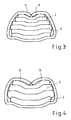
- Figures 3 and 4 show a section through the region of the crimp contact 8 after contacting.
- the layers of a conductor track 2 and a carrier foil 4 alternate (FIG. 3) or identical layers are superimposed (see FIG. 4), this being the double-layered cross section 11 according to the middle illustration of FIG equivalent.
- the crimp contact 8 was open prior to contacting up and has two wing-like embodiments, being used before contacting the folded end portion of the conductor 2 in the region of the wing-like embodiments and these wing-like embodiments in the shown manner are mechanically transformed, so that ultimately the crimp contact 8 defines the conductor track package and contacted electrically. Due to the configuration of the crimp contact 8, the conductor track sections (and optionally the intervening films) are compressed, resulting in a gas-tight and contact-secure connection.
- FIG. 5 shows, in addition to a first ribbon cable 1, a further ribbon cable 13, which likewise has at least one conductor track 14 as well as corresponding cover foils 15 and carrier foils 16.
- the correspondingly prepared ends of the tracks 2 and 14 are folded together (as shown in Figure 5) or individually folded and then into a contact area 17, d. H. within the crimp contact 8, inserted. Thereafter, as already described, the mechanical deformation of the crimp contact takes place, so that the conductor tracks 2 and 14 are mechanically and electrically connected to one another in the contact region 17.
Abstract
Description
Die Erfindung betrifft ein elektrisches Flachbandkabel mit zumindest einer auf einem Träger, insbesondere eine Trägerfolie, angeordneten flachen elektrischen Leiterbahn gemäß den Merkmalen des Oberbegriffes des Patentanspruchs 1.The invention relates to an electrical ribbon cable with at least one arranged on a support, in particular a carrier film, flat electrical conductor track according to the features of the preamble of
Solche elektrischen Flachbandkabel sind bekannt und kommen dort zum Einsatz, wo nicht genügend Bauraum für übliche Rundkabel zur Verfügung steht, die darüber hinaus auch ein höheres Gewicht gegenüber Flachbandkabel haben. Zur Kontaktierung von solchen Flachbandkabeln mit weiteren Flachbandkabeln oder auch mit elektrischen, elektronischen oder dergleichen Geräte oder Module ist es erforderlich, das Flachbandkabel mit einem Steckverbinder zu versehen. Für die Kontaktierung der Leiterbahnen mit einem Steckverbinder ist es bekannt, daß die Leiterbahn mit dem Steckverbinder verlötet wird. Da auf das Flachbandkabel, insbesondere beim Einsatz unter rauhen Umgebungsbedingungen, auch Zug- bzw. Druckkräfte auf die Leiterbahn wirken, wird zusätzlich noch eine Zugentlastung in der Gestalt vorgesehen, daß eine an dem Steckverbinder angeordnete Lasche zumindest teilweise um die Leiterbahn herum gelegt wird und auf eine Art und Weise mechanisch verformt wird, daß diese Lasche die Leiterbahn durchstößt. Dadurch wird jedoch die Leiterbahn geschwächt, so daß die Gefahr besteht, daß die Leiterbahn bei Beanspruchung, insbesondere hervorgerufen durch Vibrationen, an dieser Stelle abreißt. Damit sind dann Fehlfunktionen der angeschlossenen Geräte oder Module verbunden, die je nach Art der Wirkung sicherheitskritische Folgen haben können.Such electrical ribbon cables are known and are used where not enough space for conventional round cable is available, which also have a higher weight compared to ribbon cable. For contacting such ribbon cables with other ribbon cables or with electrical, electronic or similar devices or modules, it is necessary to provide the ribbon cable with a connector. For contacting the printed conductors with a connector, it is known that the conductor is soldered to the connector. As act on the ribbon cable, especially when used in harsh environmental conditions, tensile or compressive forces on the conductor, a strain relief is additionally provided in the form that a arranged on the connector tab is at least partially placed around the conductor around and on a way is mechanically deformed, that this tab pierces the conductor track. As a result, however, the conductor is weakened, so that there is a risk that the conductor under stress, in particular caused by vibrations, tears off at this point. This then malfunctions of the connected devices or modules are connected, which can have safety-critical consequences depending on the nature of the effect.
Aus der US 3,727,168 ist eine Vorrichtung bekannt, bei der zwei Flachbandkabel mit Steckverbindern versehen werden, umgebogen werden und zusammen in jeweils einem Steckergehäuse die Steckverbinder festgelegt werden. Die elektrischen Flachbandkabel weisen eine Vielzahl von in etwa parallel verlaufenden flachen elektrischen Leiterbahnen auf, die auf einer Trägerfolie angeordnet sind. Am Ende bzw. im Mittenbereich des Flachbandkabels wird eine Deckfolie über der jeweiligen elektrischen Leiterbahn entfernt und dort mittels einer Crimpverbindung ein Steckverbinder angeordnet. Die Details hierzu sind der Figur 4 der US 3,727,168 zu entnehmen. Entlang einer Linie (Bezugsziffer 34), an der das Flachbandkabel gefaltet wird, werden die elektrischen Leiterbahnen teilweise freigelegt. Die Anordnung des Steckverbinders durch Crimpen erfolgt nur in einem Bereich links der Trennlinie, wobei nach dem Ancrimpen das Flachbandkabel entlang der Trennlinie gefaltet wird, was in Figur 5 erkennbar ist. Das bedeutet, dass der freigelegte Bereich der Leiterbahn zum Ancrimpen des Steckverbinders nur teilweise freigelegt wird und seine ursprüngliche Form sowohl vor als auch nach dem Ancrimpen beibehält. Denn erst nachdem der Steckverbinder an dem teilweise freigelegten Ende oder Bereich des Flachbandkabels angecrimpt worden ist, erfolgt die Umfaltung des Flachbandkabels, ohne dass davon der Kontaktbereich des Steckverbinders oder dessen Leiterbahn betroffen ist.From US 3,727,168 a device is known in which two ribbon cables are provided with connectors, are bent and the connectors are set together in each case a connector housing. The electrical ribbon cables have a plurality of approximately parallel flat electrical conductor tracks, which are arranged on a carrier foil. At the end or in the middle region of the ribbon cable is a Cover film over the respective electrical conductor track removed and arranged there by means of a crimp connection a connector. The details of this can be found in FIG. 4 of US Pat. No. 3,727,168. Along a line (reference numeral 34) at which the ribbon cable is folded, the electrical traces are partially exposed. The arrangement of the connector by crimping takes place only in an area to the left of the dividing line, wherein after crimping the ribbon cable along the dividing line is folded, which can be seen in Figure 5. This means that the exposed portion of the track for crimping the connector is only partially exposed and retains its original shape both before and after crimping. Because only after the connector has been crimped to the partially exposed end or region of the ribbon cable, the refolding of the ribbon cable, without affecting the contact region of the connector or its conductor is effected.
Aus der US 5,040,997 geht ein Steckverbinder für eine Flachbandleitung als bekannt hervor, bei dem eine Flachbandleitung in ihrem Endbereich umgebogen und in ein Steckverbindergehäuse eingelegt und dort elektrisch kontaktiert wird. Hierbei handelt es sich nicht um eine Kontaktierung mittels eines Crimpkontaktes.From US Pat. No. 5,040,997, a connector for a ribbon cable is known, in which a ribbon cable is bent over in its end region and inserted into a connector housing where it is electrically contacted. This is not a contact by means of a crimp contact.
Der Erfindung liegt daher die Aufgabe zugrunde, ein elektrisches Flachbandkabel mit einem Steckverbinder zur Verfügung zu stellen, mit dem die eingangs geschilderten Nachteile vermieden werden, und das die Kontaktierung einer elektrischen Leiterbahn eines Flachbandkabels an einem Crimpkontakt verbessert.The invention is therefore an object of the invention to provide an electrical ribbon cable with a connector available, with which the above-described disadvantages are avoided, and improves the contacting of an electrical conductor of a ribbon cable to a crimp.
Diese Aufgabe ist durch die Merkmale des Patentanspruchs 1 gelöst.This object is solved by the features of
Erfindungsgemäß ist vorgesehen, daß die Leiterbahn an einem Ende vollständig elektrisch leitend freigelegt und zumindest einmal umgefaltet wird, wobei das freigelegte und umgefaltete Ende mit einem Steckverbinder, insbesondere einem Stecker oder einer Buchse verbunden wird und der Steckverbinder einen Crimpkontakt aufweist, wobei das freigelegte und umgefaltete Ende der Leiterbahn durch mechanische Umformung des Crimpkontaktes in diesem festgelegt wird. Dadurch erhöht sich der ansonsten recht dünne Querschnitt der Leiterbahn, so daß aufgrund des erhöhten Leitungsquerschnittes ein höherer Stromfluß möglich ist, wobei gleichzeitig aufgrund des vergrößerten Querschnittes auch eine höhere mechanische Stabilität für die Kontaktierung mit dem Steckverbinder zur Verfügung steht. In vorteilhafter Weise können dadurch Löt- oder ähnliche Vorgänge vermieden werden, so daß die Leiterbahn lediglich durch mechanische Umformung eines Teils des Steckverbinders verbunden wird. Das Umfalten der Leiterbahn im Kontaktbereich hat darüber hinaus noch den Vorteil, daß die übereinanderliegenden Leiterbahnabschnitte vor äußeren Einflüssen, insbesondere vor Feuchtigkeits-und Temperatureinflüssen, geschützt sind, so daß dadurch die Kontaktsicherheit verbessert wird.According to the invention it is provided that the conductor is fully electrically conductive exposed at one end and folded over at least once, wherein the exposed and folded end with a connector, in particular a plug or a socket is connected and the connector has a crimp contact, wherein the exposed and folded End of the conductor is determined by mechanical deformation of the crimp contact in this. This increases the otherwise very thin cross-section of the conductor, so that a higher current flow is possible due to the increased line cross section, at the same time due to the enlarged cross section and a higher mechanical stability for contacting with the Connector is available. Advantageously, this soldering or similar processes can be avoided, so that the conductor is connected only by mechanical deformation of a part of the connector. The folding over of the conductor track in the contact area moreover has the further advantage that the superimposed conductor track sections are protected against external influences, in particular against moisture and temperature influences, so that the contact reliability is thereby improved.
Aufgrund der mechanischen Umformung des Crimpkontakte ist zum einen eine Zugentlastung gegeben, so daß weitere Mittel für eine Zugentlastung enfallen können, aber nicht müssen. Außerdem erfolgt die mechanische Umformung in einer solchen Weise, daß der Bereich der umgefalteten Leiterbahnabschnitte (wo insbesondere auch noch Träger- und/oder Deckfolien dazwischenliegen können) von dem Crimpkontakt (oder mehreren) zusammengedrückt werden, wodurch sich die Kontaktsicherheit weiter erhöht. Außerdem wird der Bereich der umgefalteten Leiterbahnabschnitte durch den Crimpkontakt umschlossen, so daß ein Kontaktbereich entsteht, der vor äußeren Einflüssen, insbesondere Feuchtigkeits- und Temperatureinflüssen, geschützt ist. Je nach Ausgestaltung des Crimpkontaktes kann auch erreicht werden, daß dieser Kontaktbereich vollständig gasdicht abgeschlossen ist.Due to the mechanical deformation of the crimp contacts, on the one hand there is a strain relief so that further means for a strain relief can be omitted, but need not. In addition, the mechanical deformation is carried out in such a manner that the area of the folded conductor track sections (where in particular even carrier and / or cover sheets may intervene) of the crimp contact (or more) are compressed, whereby the contact reliability increases further. In addition, the area of the folded conductor track sections is enclosed by the crimp contact, so that a contact area is formed, which is protected from external influences, in particular moisture and temperature influences. Depending on the configuration of the crimp contact can also be achieved that this contact area is completed completely gas-tight.
In Weiterbildung der Erfindung wird das freigelegte Ende der Leiterbahn mehrfach umgefaltet. Dadurch erhöht sich der Leitungsquerschnitt im Kontaktbereich mit dem Steckverbinder, so daß dadurch die Kontaktsicherheit weiter verbessert wird. Außerdem hat das mehrfache Umfalten den Vorteil, daß insgesamt aufgrund der ansonsten recht dünnen Leiterbahnen ein dickeres Ende des Flachbandkabels zur Verfügung steht, welches bei der Handhabung, insbesondere bei der Kontaktierung mit dem Steckverbinder, zu einer Vereinfachung führt.In a further development of the invention, the exposed end of the conductor is folded several times. As a result, the line cross section increases in the contact region with the connector, thereby further improving the contact reliability. In addition, the multiple folding has the advantage that overall due to the otherwise fairly thin conductor tracks, a thicker end of the ribbon cable is available, which leads to a simplification in handling, especially when contacting the connector.
In Weiterbildung der Erfindung werden mehrere Leiterbahnen mit dem Steckverbinder verbunden. So ist es zum einen möglich, daß bei einem Flachbandkabel, welches mehrere parallel zueinander angeordnete Leiterbahnen aufweist, zwei oder mehr Leiterbahnen mit einem einzigen Steckverbinder zu verbinden. Alternativ oder ergänzend dazu ist es auch möglich, jeweils eine oder mehrere Leiterbahnen eines Flachbandkabels mit jeweils einer Leiterbahn oder mehrerer Leiterbahnen zumindest eines weiteren Flachbandkabels zu verbinden. Dies kommt immer dann in Frage, wenn mehrere elektrische oder elektronische Module (wie beispielsweise Sensoren, Aktuatoren oder Steuereinheiten) mit ein und demselben Signal, welches über die Leiterbahn übertragen wird, versorgt werden sollen.In the invention, a plurality of interconnects are connected to the connector. Thus, it is possible for a flat-ribbon cable which has a plurality of interconnects arranged parallel to one another to connect two or more interconnects to a single connector. Alternatively or additionally, it is also possible in each case to connect one or more conductor tracks of a ribbon cable with in each case one conductor track or several conductor tracks of at least one further ribbon cable. This is always possible when multiple electrical or electronic modules (such as sensors, actuators or Control units) with one and the same signal, which is transmitted via the conductor to be supplied.
Gemäß der Erfindung wird die Leiterbahn auf beiden Seiten freigelegt. Besteht das Flachbandkabel aus mehreren parallel zueinander angeordneten Leiterbahnen, die einerseits auf einer Trägerfolie angeordnet sind und andererseits von einer Deckfolie geschützt sind, werden in vorteilhafterweise vor dem Umfalten und dem Kontaktieren mit dem Steckverbinder die Endbereiche einer oder mehrerer Leiterbahnen sowohl von der Trägerfolie als auch von der Deckfolie befreit, damit nur noch der volständige elektrisch leitende Bereich der Leiterbahn zur Kontaktierung kommt.According to the invention, the track is exposed on both sides. If the ribbon cable consists of a plurality of mutually parallel conductor tracks, which are arranged on the one hand on a carrier film and on the other hand protected by a cover sheet, advantageously the end portions of one or more tracks both from the carrier film and from before folding and contacting the connector the cover sheet freed, so that only the fully conductive electrically conductive area of the conductor comes to the contact.
In Weiterbildung der Erfindung ist jeweils eine Leiterbahn mit einem Steckverbinder verbunden, so daß nach der Verbindung der umgefalteten Leiterbahnen mit dem Steckverbinder an einem Ende des Flachbandkabels mehrere parallel zueinander angeordnete Steckverbinder zur Verfügung stehen. Diese können in einen zugehörigen Kontaktpartner eingesteckt werden, wobei es zur Verbesserung der Handhabung und zur Vermeidung von Berührungen der einzelnen Steckverbinder Mittel vorgesehen werden können, die die parallel zueinander liegenden Steckverbinder auf Distanz halten. Dies kann insbesondere dadurch geschehen, daß mehrere Steckverbinder, insbesondere alle Steckverbinder, die mit den Leiterbahnen verbunden sind, von einem Gehäuse umgeben werden. Dieses Gehäuse kann beispielsweise aus zwei Hälften bestehen, wobei die Steckverbinder in die eine Gehäusehälfte eingelegt und durch die zweite Gehäusehälfte festgelegt werden. Alternativ ist es auch denkbar, daß die einzelnen Steckverbinder in ihrer Lage zueinander fixiert und anschließend mit Kunststoff umspritzt werden.In a further development of the invention, a conductor track is in each case connected to a plug connector, so that a plurality of mutually parallel connectors are available after the connection of the folded conductor tracks to the connector at one end of the ribbon cable. These can be plugged into an associated contact, and it can be provided to improve the handling and to avoid contact with the individual connectors means that keep the parallel connectors at a distance. This can be done in particular by the fact that a plurality of connectors, in particular all the connectors which are connected to the conductor tracks, are surrounded by a housing. This housing may for example consist of two halves, wherein the connectors are inserted into the one half of the housing and fixed by the second housing half. Alternatively, it is also conceivable that the individual connectors are fixed in position to each other and then encapsulated in plastic.
In Weiterbildung der Erfindung weist der Steckverbinder Flügel auf, die nach dem mechanischen Umformen die Leiterbahn an dem Steckverbinder festlegen, ohne die Leiterbahn zu durchstoßen. Dadurch ist zusätzlich zu dem Crimpkontakt eine weitere Zugentlastung gegeben, die den Kontaktbereich des Crimpkontaktes vor Zug- und Druckkräften entlastet, ohne die Leiterbahn mechanisch zu beschädigen.In a further development of the invention, the connector has wings which define the conductor track on the connector after the mechanical forming, without piercing the conductor track. As a result, in addition to the crimp contact, a further strain relief is provided, which relieves the contact area of the crimp contact from tensile and compressive forces without mechanically damaging the conductor track.
Aufgrund der vorbeschriebenen Möglichkeiten steht also ein Verfahren zur Kontaktierung zumindest einer Leiterbahn eines Flachbandkabels mit einem Steckverbinder zur Verfügung, bei dem der elektrisch leitende freigelegte Bereich der Leiterbahn zumindest einmal umgefaltet wird und mit einem Steckverbinder verbunden wird. Diese Verbindung erfolgt insbesondere durch mechanische Umformung eines Crimpkontaktes an dem Steckverbinder, wobei das Paket der umgefalteten Leiterbahnabschnitte zusammengedrückt wird, wodurch eine erhöhte Kontaktsicherheit und eine Zugentlastung gegeben ist.Due to the possibilities described above, a method is therefore available for contacting at least one printed circuit of a ribbon cable with a plug connector, in which the electrically conductive exposed region of the printed conductor is at least once folded over and connected to a plug connector. This connection takes place in particular by mechanical deformation of a crimp contact on the Connector, wherein the package of the folded conductor track sections is compressed, whereby an increased contact safety and a strain relief is given.
Verschiedene Ausgestaltungen der Erfindung, auf die diese jedoch nicht beschränkt ist, sind im Folgenden beschrieben und anhand der Figuren erläutert.Various embodiments of the invention, to which this is not limited, are described below and explained with reference to the figures.
Es zeigen:
Figur 1- die verschiedenen Arbeitsschritte für die Verbindung der Leiterbahn mit dem Steckverbinder,
Figur 2- verschiedene Varianten der Umfaltung der Leiterbahn,
Figuren 3 und 4- Querschnitt durch den Bereich eines Crimpkontaktes,
Figur 5- die Verbindung mehrerer Leiterbahnen mit einem Steckverbinder.
- FIG. 1
- the various steps for connecting the track to the connector,
- FIG. 2
- different variants of the refolding of the conductor track,
- FIGS. 3 and 4
- Cross section through the area of a crimp contact,
- FIG. 5
- the connection of several tracks with a connector.
Figur 1 zeigt die verschiedenen Arbeitsschritte, die erforderlich sind, um ein Flachbandkabel mit einem Steckverbinder in der erfindungsgemäßen Art und Weise zu versehen. Ein Flachbandkabel 1 weist zumindest eine Leiterbahn 2 auf, wobei in der Regel mehrere Leiterbahnen 2 parallel zueinander angeordnet sind und das Flachbandkabel 1 bilden. Diese Leiterbahnen 2 werden einerseits von einer Deckfolie 3 abgedeckt und befinden sich andererseits auf einer Trägerfolie 4, wobei die Deckfolie 3 und die Trägerfolie 4 aus unterschiedlichem oder gleichem Material bestehen können und gleich oder unterschiedlich dick sind.Figure 1 shows the various operations required to provide a ribbon cable with a connector in the manner of the present invention. A
In einem ersten Arbeitsschritt wird die Leiterbahn 2 auf beiden Seiten sowohl von der Deckfolie 3 als auch von der Trägerfolie 4 befreit. Im zweiten Arbeitsschritt wird das freigelegte Ende der Leiterbahn 2 einmal umgefaltet und in einem dritten Arbeitsschritt der Endbereich der einmal umgefalteten Leiterbahn nochmals umgefaltet. Im vierten Arbeitsschritt wird das äußerste Leiterbahnpaket noch einmal umgefaltet, so daß ein Ende der Leiterbahn 2 zur Verfügung steht, welches nun aus fünf übereinandergelegten Leiterbahnabschnitten besteht.In a first step, the
Ein Steckverbinder 5, der mit dem derart vorbereiteten Leiterbahnende kontaktiert werden soll, besteht beispielsweise aus einem Kontaktstift 6 und ist mit einem Widerhaken 7 versehen, welcher verhindert, daß der Steckverbinder 5 nach dem Einsetzen in ein Gehäuse (hier nicht gezeigt) aus diesem herausgezogen werden kann. Weiterhin weist der Steckverbinder 5 einen Crimpkontakt 8 auf, in dessen Bereich das gefaltete Ende der Leiterbahn 2 eingelegt wird. Die Kontaktierung in diesem Bereich des Crimpkontaktes 8 wird zu Figur 3 und 4 noch beschrieben. Ein weiterer, in Figur 1 unten rechts gezeigter Steckverbinder 5 kann noch zusätzliche eine Zugentlastung 9 aufweisen, die durch mechanische Umformung um den Endbereich des Flachbandkabels 1 mit Deckfolie 3 und Trägerfolie 4 gelegt wird, um eine weitere Zugentlastung zu realisieren, ohne daß das Flachbandkabel 1 mechanisch beschädigt wird. Eine solche Zugentlastung 9 kann, muß aber nicht an dem Steckverbinder 5 vorgesehen sein.A
Figur 2 zeigt im oberen und im mittleren Drittel jeweils ein Flachbandkabel 1, bei dem die Leiterbahn von ihrer Deckfolie 3 befreit ist, die Trägerfolie 4 jedoch noch vorhanden ist. Je nach Anzahl und Art der Umfaltvorgänge ergibt sich ein vierlagiger Querschnitt 10 oder ein doppellagiger Querschnitt 11 des Endbereiches der Leiterbahn 2, wobei auch noch mehr als ein- oder zweifache Umfaltvorgänge und auch andere Umfaltvorgänge, als sie in Figur 1 und 2 beschrieben sind, denkbar sind. Im unteren Drittel der Figur 2 ist nochmals der Steckverbinder 5 gezeigt, mit dem der umgefaltete Bereich der Leiterbahn 2 verbunden werden soll.Figure 2 shows in the upper and in the middle third each a
Die Figuren 3 und 4 zeigen einen Schnitt durch den Bereich des Crimpkontaktes 8 nach der Kontaktierung. Je nach Art der Umfaltung ist zu erkennen, daß sich die Schichten einer Leiterbahn 2 und einer Trägerfolie 4 abwechseln (Figur 3) oder aber gleiche Schichten übereinanderliegen (s. Figur 4), wobei dies dem doppellagigen Querschnitt 11 gemäß der mittleren Abbildung der Figur 2 entspricht.Figures 3 and 4 show a section through the region of the
In diesen Figuren 3 und 4 ist erkennbar, daß der Crimpkontakt 8 vor der Kontaktierung nach oben offen war und zwei flügelartige Ausgestaltungen aufweist, wobei vor der Kontaktierung der umgefaltete Endbereich der Leiterbahn 2 in den Bereich der flügelartigen Ausgestaltungen eingesetzt wird und diese flügelartigen Ausgestaltungen in der gezeigten Art und Weise mechanisch umgeformt werden, so daß letztendlich der Crimpkontakt 8 das Leiterbahnpaket festlegt und elektrisch kontaktiert. Aufgrund der Ausgestaltung des Crimpkontaktes 8 werden die Leiterbahnabschnitte (und gegebenenfalls die dazwischen liegenden Folien) zusammengedrückt, wodurch sich eine gasdichte und kontaktsichere Verbindung ergibt.In these Figures 3 and 4 it can be seen that the
Figur 5 zeigt neben einem ersten Flachbandkabel 1 ein weiteres Flachbandkabel 13, welches ebenfalls mindestens eine Leiterbahn 14 sowie entsprechende Deckfolien 15 und Trägerfolien 16 aufweist. Die entsprechend vorbereiteten Enden der Leiterbahnen 2 und 14 werden zusammen umgefaltet (wie in Figur 5 gezeigt) oder einzeln umgefaltet und dann in einen Kontaktbereich 17, d. h. innerhalb des Crimpkontaktes 8, eingelegt. Danach erfolgt- wie schon beschrieben - die mechanische Umformung des Crimpkontaktes, so daß die Leiterbahnen 2 und 14 im Kontaktbereich 17 mechanisch und elektrisch miteinander verbunden werden. Anschließend wird zumindest der Steckverbinder 5, insbesondere aber auch die Enden der beiden Flachbandkabel 1 und 13, mit einem Gehäuse 18 umgeben, so daß dadurch eine kontaktsichere Steckverbindung realisiert ist, die vor äußeren Einflüssen, wie Temperatur und Feuchtigkeit und Verschmutzung durch elektrisch leitende Partikel wirksam geschützt ist.FIG. 5 shows, in addition to a
Claims (6)
- Electrical flat ribbon cable (1, 13) having at least one flat electrical conductor track (2, 14) arranged on a carrier, in particular a carrier film (4, 16), characterized in that the conductor track (2, 14) is completely electrically conductively exposed and folded over at least once at one end, the exposed and folded-over end being connected to a plug-in connector (5), in particular a plug or a socket, the plug-in connector (5) having a crimping contact (8), and the exposed and folded-over end of the conductor track (2, 14) being fixed in the crimping contact (8) in a gas-tight manner owing to mechanical deformation of said crimping contact (8).
- Electrical flat ribbon cable (1, 13) according to Claim 1, characterized in that the exposed end of the conductor track (2, 14) is folded over a plurality of times.
- Electrical flat ribbon cable (1, 13) according to either of Claims 1 and 2, characterized in that a plurality of conductor tracks (2, 14) are connected to the plug-in connector (5).
- Electrical flat ribbon cable (1, 13) according to one of the preceding claims, characterized in that in each case one conductor track (2, 14) is connected to a plug-in connector (5).
- Electrical flat ribbon cable (1, 13) according to one of the preceding claims, characterized in that a plurality of plug-in connectors (5), in particular all of the plug-in connectors (5) which are connected to the conductor tracks (2, 14), can be surrounded by a housing (18).
- Electrical flat ribbon cable (1, 13) according to one of the preceding claims, characterized in that the plug-in connector (5) has a strain-relief device (9), the strain-relief device (9) fixing the conductor track (2, 14) on the plug-in connector (5) once it has been mechanically deformed without passing through the conductor track (2, 14).
Applications Claiming Priority (4)
| Application Number | Priority Date | Filing Date | Title |
|---|---|---|---|
| DE10016260 | 2000-03-03 | ||
| DE10016260 | 2000-03-03 | ||
| DE10104354A DE10104354A1 (en) | 2000-03-03 | 2001-02-01 | Electrical ribbon cable with folded electrical conductor tracks |
| DE10104354 | 2001-02-01 |
Publications (3)
| Publication Number | Publication Date |
|---|---|
| EP1130687A2 EP1130687A2 (en) | 2001-09-05 |
| EP1130687A3 EP1130687A3 (en) | 2004-10-13 |
| EP1130687B1 true EP1130687B1 (en) | 2006-05-03 |
Family
ID=26005139
Family Applications (1)
| Application Number | Title | Priority Date | Filing Date |
|---|---|---|---|
| EP01104347A Expired - Lifetime EP1130687B1 (en) | 2000-03-03 | 2001-02-23 | Electrical flat cable with folded electrically conductive paths |
Country Status (4)
| Country | Link |
|---|---|
| EP (1) | EP1130687B1 (en) |
| AT (1) | ATE325444T1 (en) |
| DE (2) | DE10104354A1 (en) |
| ES (1) | ES2263521T3 (en) |
Families Citing this family (5)
| Publication number | Priority date | Publication date | Assignee | Title |
|---|---|---|---|---|
| DE10213757A1 (en) * | 2001-04-07 | 2003-01-30 | Wet Automotive Systems Ag | Cable and manufacturing process |
| JP4376682B2 (en) * | 2004-04-09 | 2009-12-02 | 矢崎総業株式会社 | Wire end caulking structure |
| EP2339592A3 (en) * | 2009-12-23 | 2011-12-14 | Hitachi-LG Data Storage Korea, Inc. | Cable, cable connector and cable assembly |
| DE102010005021A1 (en) * | 2010-01-19 | 2011-07-21 | Continental Automotive GmbH, 30165 | Flat conductor device and electrical energy storage |
| JP5824368B2 (en) * | 2012-01-18 | 2015-11-25 | 矢崎総業株式会社 | Flat circuit body with terminals |
Family Cites Families (3)
| Publication number | Priority date | Publication date | Assignee | Title |
|---|---|---|---|---|
| BE791001A (en) * | 1971-11-08 | 1973-05-07 | Amp Inc | FLAT ELECTRIC CABLE |
| US5040997A (en) * | 1990-06-08 | 1991-08-20 | The Foxboro Company | Flex circuit connector assembly and method for manufacturing the same |
| DE9414307U1 (en) * | 1994-08-23 | 1994-12-08 | Thomas & Betts Corp | Flat / round cable connection device |
-
2001
- 2001-02-01 DE DE10104354A patent/DE10104354A1/en not_active Withdrawn
- 2001-02-23 AT AT01104347T patent/ATE325444T1/en not_active IP Right Cessation
- 2001-02-23 DE DE50109660T patent/DE50109660D1/en not_active Expired - Lifetime
- 2001-02-23 EP EP01104347A patent/EP1130687B1/en not_active Expired - Lifetime
- 2001-02-23 ES ES01104347T patent/ES2263521T3/en not_active Expired - Lifetime
Also Published As
| Publication number | Publication date |
|---|---|
| DE50109660D1 (en) | 2006-06-08 |
| EP1130687A2 (en) | 2001-09-05 |
| EP1130687A3 (en) | 2004-10-13 |
| ES2263521T3 (en) | 2006-12-16 |
| DE10104354A1 (en) | 2001-09-06 |
| ATE325444T1 (en) | 2006-06-15 |
Similar Documents
| Publication | Publication Date | Title |
|---|---|---|
| DE102010031416B4 (en) | Card edge connector and method for its production | |
| DE60211880T2 (en) | METHOD AND DEVICE FOR USING A CONNECTOR FOR FLEXIBLE FLAT CABLES | |
| EP2728982A1 (en) | Circuit board module for a control device, control device for a motor vehicle and signal processing assembly | |
| DE2800006A1 (en) | UNIVERSALLY PROGRAMMABLE SHORT CIRCUIT PLUG FOR A SOCKET OF AN INTEGRATED CIRCUIT | |
| EP3476010B1 (en) | Electrical conductor connection | |
| EP2728983A1 (en) | Circuit board module for a control device, control device for a motor vehicle and signal processing assembly | |
| DE69931591T2 (en) | Circuit board for modular plug | |
| DE102021117180A1 (en) | Electrical connection for flexible flat cables | |
| DE102006011262A1 (en) | Electrical connector and method of making the same | |
| EP1130687B1 (en) | Electrical flat cable with folded electrically conductive paths | |
| EP0980322B1 (en) | Sensor circuit for automobiles | |
| EP3698438B1 (en) | Electric contacting device | |
| DE102012218433A1 (en) | Contact element for contact arrangement, has shoulder portion arranged between contact portion and insertion portion, which is protruded laterally to contact portion and is adapted to introduce pressing force into insertion portion | |
| EP2367202B1 (en) | Method for producing an electrically conductive connection between a contact and a counter contact | |
| DE3937089C2 (en) | Electrical connection for foil conductors | |
| DE102021117178A1 (en) | Electrical connection for flexible flat cables | |
| DE19632817A1 (en) | Electrical cable tree for multi-port electrical device | |
| DE102021117179A1 (en) | Electrical connection for flexible flat cables | |
| DE3024643A1 (en) | FLAT ELECTRIC MULTI-WIRE CONNECTION SYSTEM | |
| EP1083627B1 (en) | Electrical connector assembly | |
| EP3740050A1 (en) | Printed circuit board with a connector | |
| DE19738588B4 (en) | Electrical component with a sheath and with a connection area arranged in the sheath and method for producing such an electrical component | |
| DE10353162B4 (en) | Flat cable connector and method of attaching the flat cable to the connector | |
| EP1162694B1 (en) | Apparatus for connecting electrical wires | |
| WO2017178007A1 (en) | Plug connector with a conductive rubber element |
Legal Events
| Date | Code | Title | Description |
|---|---|---|---|
| PUAI | Public reference made under article 153(3) epc to a published international application that has entered the european phase |
Free format text: ORIGINAL CODE: 0009012 |
|
| AK | Designated contracting states |
Kind code of ref document: A2 Designated state(s): AT BE CH CY DE DK ES FI FR GB GR IE IT LI LU MC NL PT SE TR |
|
| AX | Request for extension of the european patent |
Free format text: AL;LT;LV;MK;RO;SI |
|
| RAP1 | Party data changed (applicant data changed or rights of an application transferred) |
Owner name: HIRSCHMANN AUTOMOTIVE GMBH |
|
| PUAL | Search report despatched |
Free format text: ORIGINAL CODE: 0009013 |
|
| AK | Designated contracting states |
Kind code of ref document: A3 Designated state(s): AT BE CH CY DE DK ES FI FR GB GR IE IT LI LU MC NL PT SE TR |
|
| AX | Request for extension of the european patent |
Extension state: AL LT LV MK RO SI |
|
| 17P | Request for examination filed |
Effective date: 20050108 |
|
| 17Q | First examination report despatched |
Effective date: 20050519 |
|
| AKX | Designation fees paid |
Designated state(s): AT DE ES FR GB IT |
|
| GRAP | Despatch of communication of intention to grant a patent |
Free format text: ORIGINAL CODE: EPIDOSNIGR1 |
|
| GRAS | Grant fee paid |
Free format text: ORIGINAL CODE: EPIDOSNIGR3 |
|
| GRAA | (expected) grant |
Free format text: ORIGINAL CODE: 0009210 |
|
| AK | Designated contracting states |
Kind code of ref document: B1 Designated state(s): AT DE ES FR GB IT |
|
| PG25 | Lapsed in a contracting state [announced via postgrant information from national office to epo] |
Ref country code: IT Free format text: LAPSE BECAUSE OF FAILURE TO SUBMIT A TRANSLATION OF THE DESCRIPTION OR TO PAY THE FEE WITHIN THE PRESCRIBED TIME-LIMIT;WARNING: LAPSES OF ITALIAN PATENTS WITH EFFECTIVE DATE BEFORE 2007 MAY HAVE OCCURRED AT ANY TIME BEFORE 2007. THE CORRECT EFFECTIVE DATE MAY BE DIFFERENT FROM THE ONE RECORDED. Effective date: 20060503 Ref country code: GB Free format text: LAPSE BECAUSE OF FAILURE TO SUBMIT A TRANSLATION OF THE DESCRIPTION OR TO PAY THE FEE WITHIN THE PRESCRIBED TIME-LIMIT Effective date: 20060503 |
|
| REG | Reference to a national code |
Ref country code: GB Ref legal event code: FG4D Free format text: NOT ENGLISH |
|
| REF | Corresponds to: |
Ref document number: 50109660 Country of ref document: DE Date of ref document: 20060608 Kind code of ref document: P |
|
| ET | Fr: translation filed | ||
| GBV | Gb: ep patent (uk) treated as always having been void in accordance with gb section 77(7)/1977 [no translation filed] |
Effective date: 20060503 |
|
| REG | Reference to a national code |
Ref country code: ES Ref legal event code: FG2A Ref document number: 2263521 Country of ref document: ES Kind code of ref document: T3 |
|
| PLBE | No opposition filed within time limit |
Free format text: ORIGINAL CODE: 0009261 |
|
| STAA | Information on the status of an ep patent application or granted ep patent |
Free format text: STATUS: NO OPPOSITION FILED WITHIN TIME LIMIT |
|
| 26N | No opposition filed |
Effective date: 20070206 |
|
| PG25 | Lapsed in a contracting state [announced via postgrant information from national office to epo] |
Ref country code: AT Free format text: LAPSE BECAUSE OF NON-PAYMENT OF DUE FEES Effective date: 20070223 |
|
| REG | Reference to a national code |
Ref country code: FR Ref legal event code: PLFP Year of fee payment: 16 |
|
| REG | Reference to a national code |
Ref country code: FR Ref legal event code: PLFP Year of fee payment: 17 |
|
| PGFP | Annual fee paid to national office [announced via postgrant information from national office to epo] |
Ref country code: DE Payment date: 20170217 Year of fee payment: 17 Ref country code: FR Payment date: 20170217 Year of fee payment: 17 |
|
| PGFP | Annual fee paid to national office [announced via postgrant information from national office to epo] |
Ref country code: ES Payment date: 20170213 Year of fee payment: 17 Ref country code: IT Payment date: 20170221 Year of fee payment: 17 |
|
| REG | Reference to a national code |
Ref country code: DE Ref legal event code: R119 Ref document number: 50109660 Country of ref document: DE |
|
| REG | Reference to a national code |
Ref country code: FR Ref legal event code: ST Effective date: 20181031 |
|
| PG25 | Lapsed in a contracting state [announced via postgrant information from national office to epo] |
Ref country code: DE Free format text: LAPSE BECAUSE OF NON-PAYMENT OF DUE FEES Effective date: 20180901 |
|
| PG25 | Lapsed in a contracting state [announced via postgrant information from national office to epo] |
Ref country code: FR Free format text: LAPSE BECAUSE OF NON-PAYMENT OF DUE FEES Effective date: 20180228 Ref country code: IT Free format text: LAPSE BECAUSE OF NON-PAYMENT OF DUE FEES Effective date: 20180223 |
|
| REG | Reference to a national code |
Ref country code: ES Ref legal event code: FD2A Effective date: 20190801 |
|
| PG25 | Lapsed in a contracting state [announced via postgrant information from national office to epo] |
Ref country code: ES Free format text: LAPSE BECAUSE OF NON-PAYMENT OF DUE FEES Effective date: 20180224 |