EP1130329A2 - Durchlauf-Wasserheizgerät - Google Patents
Durchlauf-Wasserheizgerät Download PDFInfo
- Publication number
- EP1130329A2 EP1130329A2 EP01102103A EP01102103A EP1130329A2 EP 1130329 A2 EP1130329 A2 EP 1130329A2 EP 01102103 A EP01102103 A EP 01102103A EP 01102103 A EP01102103 A EP 01102103A EP 1130329 A2 EP1130329 A2 EP 1130329A2
- Authority
- EP
- European Patent Office
- Prior art keywords
- water heater
- temperature
- target value
- logic
- line
- Prior art date
- Legal status (The legal status is an assumption and is not a legal conclusion. Google has not performed a legal analysis and makes no representation as to the accuracy of the status listed.)
- Granted
Links
Images

Classifications
-
- F—MECHANICAL ENGINEERING; LIGHTING; HEATING; WEAPONS; BLASTING
- F24—HEATING; RANGES; VENTILATING
- F24D—DOMESTIC- OR SPACE-HEATING SYSTEMS, e.g. CENTRAL HEATING SYSTEMS; DOMESTIC HOT-WATER SUPPLY SYSTEMS; ELEMENTS OR COMPONENTS THEREFOR
- F24D19/00—Details
- F24D19/10—Arrangement or mounting of control or safety devices
- F24D19/1006—Arrangement or mounting of control or safety devices for water heating systems
- F24D19/1066—Arrangement or mounting of control or safety devices for water heating systems for the combination of central heating and domestic hot water
- F24D19/1069—Arrangement or mounting of control or safety devices for water heating systems for the combination of central heating and domestic hot water regulation in function of the temperature of the domestic hot water
-
- F—MECHANICAL ENGINEERING; LIGHTING; HEATING; WEAPONS; BLASTING
- F24—HEATING; RANGES; VENTILATING
- F24H—FLUID HEATERS, e.g. WATER OR AIR HEATERS, HAVING HEAT-GENERATING MEANS, e.g. HEAT PUMPS, IN GENERAL
- F24H15/00—Control of fluid heaters
- F24H15/20—Control of fluid heaters characterised by control inputs
- F24H15/212—Temperature of the water
-
- F—MECHANICAL ENGINEERING; LIGHTING; HEATING; WEAPONS; BLASTING
- F24—HEATING; RANGES; VENTILATING
- F24H—FLUID HEATERS, e.g. WATER OR AIR HEATERS, HAVING HEAT-GENERATING MEANS, e.g. HEAT PUMPS, IN GENERAL
- F24H15/00—Control of fluid heaters
- F24H15/20—Control of fluid heaters characterised by control inputs
- F24H15/212—Temperature of the water
- F24H15/219—Temperature of the water after heating
-
- F—MECHANICAL ENGINEERING; LIGHTING; HEATING; WEAPONS; BLASTING
- F24—HEATING; RANGES; VENTILATING
- F24H—FLUID HEATERS, e.g. WATER OR AIR HEATERS, HAVING HEAT-GENERATING MEANS, e.g. HEAT PUMPS, IN GENERAL
- F24H15/00—Control of fluid heaters
- F24H15/30—Control of fluid heaters characterised by control outputs; characterised by the components to be controlled
- F24H15/355—Control of heat-generating means in heaters
- F24H15/36—Control of heat-generating means in heaters of burners
Definitions
- the invention relates to a once-through water heater according to the preamble of claim 1.
- a "warm start” function in which one in the water heater arranged small memory is kept at an adjustable temperature in order to Tap hot water very quickly to provide hot water at the tap can.
- the aim of the invention is to avoid these disadvantages and a once-through water heater to propose the type mentioned, which is simple in structure and easy to use distinguished.
- the proposed measures result in a significantly simplified operation of the Device. This means that both the outlet temperature and the Storage temperature can be set. It also ensures that there are none inconsistent settings of the setpoints comes.
- the features of claim 2 have the advantage that also on a switch for on and Switching off the "warm start” function can be dispensed with. This function can be done by the two Target value transmitters are taken over in connection with the flip-flop.
- one of the threshold switches e.g. switch through when 90% of the setting range is exceeded and the other threshold switch if the value falls below 10% of the maximum setting switch through, whereby the flip-flop is set or reset.
- FIG. 1 shows a circulating water heater 30 which is heated by a burner 31 Has heat exchanger 32.
- the heat exchanger 32 is provided with a pump 33
- Return line 34 fed with water, which after heating by the heat exchanger of one with a temperature sensor 35 provided flow line 36 is discharged.
- the line 36 leads to one Collective heating system, not shown, branches off from it a line 37 leading to a heating water / process water heat exchanger 38 leads to a via a heat exchanger return line 39
- Changeover valve 40 leads, which is connected via a line section 41 to the pump 33 on the return side.
- the temperature sensor 35 is connected to a regulating / control device 43 via a measuring line 42, which is connected via a line 44 to an electromagnet 45 of a gas valve 46, which in A gas line 47 to the burner 31 is arranged.
- a control device 43 With the control device 43 is about a line 48 connects a motor 49 to the pump 33.
- Another line 50 leads to one Electromagnet 51, which influences the switching valve 40 via a lever 52, which on the Line section 41 facing away via a line 53 with the previously mentioned heating system connected is.
- the heating water / process water heat exchanger 38 is penetrated by a tap 54 which can be closed with a nozzle 55.
- the nozzle 54 is connected to the pipe coil with a Cold water network 56 connected.
- a Temperature sensor. 57 is provided, which is connected to the control and regulating device 43 via a measurement line 58 connected is.
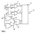
- a setpoint generator is provided, which is in the form of a variable resistance is executed.
- the center connection 21 of the target value transmitter 15 is each an input of two comparators 4, 6 connected via connecting lines 22, 23.
- the second input of the comparator 4 is not connected via a connecting line 8 to one shown, the temperature of the hot water sensor and the second input of the Comparator 6 is via a connecting line 10 with a temperature, also not shown, the temperature connected in a small memory sensor.
- the connecting line 23 is connected to a further connecting line 24 via which one Connection of the center connection 21 of the setpoint generator 15 to the inputs of two Threshold switches 17 and 18 is made.
- the threshold switch 17 turns on when the set target value is more than 90% of the maximum possible target value.
- the Threshold switch 18 switches through when the target value set with the target value transmitter 15 is less than 10% of the maximum possible target value.
- the outputs of the comparators 4 and 6 are via connecting lines 5 and 7 with a logic 13 connected. This is also the output Q of a flip-flop 16 via a connecting line 12 connected. The inputs of the flip-flop 16 are connected to the outputs via connecting lines 19 and 20 the threshold switch 17 or 18 connected.
- the logic is via a control line 14 with auxiliary units, not shown, for a burner, such as Gas valve, blower and the like connected
- the setpoint generator 15 If the setpoint generator 15 is set to over 90% of the maximum possible value during operation, then gives the threshold switch 17 a signal and sets the flip-flop 16, whereby the logic 13 in the Operating mode "warm start” is set.
- the logic ensures that the burner is not tapped Process water is kept or put into operation so far that the temperature in the Small memory is kept at a value corresponding to the set target value. It has to are not necessarily the setpoint specified for the hot water temperature, but it can be a value derived from this according to a specific algorithm act.
- the threshold switch 18 outputs a signal to the flip-flop 16 and resets it, whereby the operating mode "warm start” is switched off.
- the operating mode "warm start” is activated by a, even if only briefly Exceeding 90% of the maximum possible setpoint when setting the setpoint.
- the setpoint generator 15 can be used to switch the "warm start” operating mode on and off, as well as the specification of the setpoints for the temperature of the hot water and the small storage tank respectively.
Landscapes
- Engineering & Computer Science (AREA)
- Thermal Sciences (AREA)
- Chemical & Material Sciences (AREA)
- Combustion & Propulsion (AREA)
- Mechanical Engineering (AREA)
- General Engineering & Computer Science (AREA)
- Physics & Mathematics (AREA)
- Control Of Combustion (AREA)
- Domestic Hot-Water Supply Systems And Details Of Heating Systems (AREA)
- Resistance Heating (AREA)
- Rear-View Mirror Devices That Are Mounted On The Exterior Of The Vehicle (AREA)
- Heat-Pump Type And Storage Water Heaters (AREA)
- Massaging Devices (AREA)
- Steam Or Hot-Water Central Heating Systems (AREA)
- Instantaneous Water Boilers, Portable Hot-Water Supply Apparatuses, And Control Of Portable Hot-Water Supply Apparatuses (AREA)
- Cookers (AREA)
- Percussion Or Vibration Massage (AREA)
Abstract
Description
- Fig. 1
- zeigt einen Umlaufwasserheizer und
- Fig. 2
- zeigt die schematische Steuerung eines erfindungsgemäßen Umlaufwasserheizers.
Claims (3)
- Durchlauf-Wasserheizgerät mit einem eingebauten Kleinspeicher und einer Steuerung für mindestens eine Wärmequelle zur Beaufschlagung des Wasserheizers und des Kleinspeichers, wobei mindestens ein Sollwert-Geber (15) vorgesehen ist, dadurch gekennzeichnet, daß lediglich ein Sollwertgeber (15) zur Einstellung der Auslauftemperatur des Wasserheizers vorgesehen ist, der über je einen mit einem die Auslauftemperatur erfassenden Temperaturfühler und einen mit einem im Kleinspeicher angeordneten Temperaturfühler verbundenen Vergleichern (4, 6) mit einer einen Brenner steuernden Logik (13) verbunden ist.
- Durchlauf-Wasserheizer nach Anspruch 1, dadurch gekennzeichnet, daß der Soll-Wertgeber (15) weiters über zwei parallel geschaltete Schwellwertschalter (17, 18) deren Ausgänge mit einem Flip-Flop (16) verbunden sind, dessen Ausgang ebenfalls mit der Logik (13) verbunden ist.
- Durchlauf-Wasserheizer nach Anspruch 2, dadurch gekennzeichnet, daß einer der beiden Schwellwertschalter (17, 18) bei Überschreiten eines hohen Soll-Wertpegels der Auslauftemperatur ein Ausgangssignal liefert und der andere Schwellwertschalter (18) bei Unterschreiten eines niedrigen Soll-Wertpegels der Auslauftemperatur ein Ausgangssignal liefert.
Priority Applications (1)
| Application Number | Priority Date | Filing Date | Title |
|---|---|---|---|
| AT01102103T ATE321982T1 (de) | 2000-02-02 | 2001-01-31 | Durchlauf-wasserheizgerät |
Applications Claiming Priority (2)
| Application Number | Priority Date | Filing Date | Title |
|---|---|---|---|
| AT0015400A AT412907B (de) | 2000-02-02 | 2000-02-02 | Durchlauf-wasserheizer |
| AT1542000 | 2000-02-02 |
Publications (3)
| Publication Number | Publication Date |
|---|---|
| EP1130329A2 true EP1130329A2 (de) | 2001-09-05 |
| EP1130329A3 EP1130329A3 (de) | 2003-01-02 |
| EP1130329B1 EP1130329B1 (de) | 2006-03-29 |
Family
ID=3647925
Family Applications (1)
| Application Number | Title | Priority Date | Filing Date |
|---|---|---|---|
| EP01102103A Expired - Lifetime EP1130329B1 (de) | 2000-02-02 | 2001-01-31 | Durchlauf-Wasserheizgerät |
Country Status (6)
| Country | Link |
|---|---|
| EP (1) | EP1130329B1 (de) |
| AT (2) | AT412907B (de) |
| DE (2) | DE50109341D1 (de) |
| DK (1) | DK1130329T3 (de) |
| ES (1) | ES2261280T3 (de) |
| PT (1) | PT1130329E (de) |
Family Cites Families (10)
| Publication number | Priority date | Publication date | Assignee | Title |
|---|---|---|---|---|
| DE3019318A1 (de) * | 1980-05-21 | 1981-11-26 | Solar Wärmetechnik GmbH, 7980 Ravensburg | Heizungs- und warmwasserbereitungsanlage |
| DE3311127C2 (de) * | 1983-03-26 | 1994-02-24 | Fa. Rud. Otto Meyer, 2000 Hamburg | Verfahren zur Regelung von im Verbund geschalteten, mit einem Pufferspeicher verbundenen Wärmeerzeugern und Anordnung zur Durchführung des Verfahrens |
| DE3507137A1 (de) * | 1985-02-28 | 1986-08-28 | Happel GmbH & Co, 4690 Herne | Heizgeraet |
| WO1992006336A1 (en) * | 1990-09-27 | 1992-04-16 | Gledhill (Water Storage) Limited | Improvements relating to central boiler systems |
| GB2250334B (en) * | 1990-11-21 | 1994-09-07 | Imi Range Ltd | Waterheating apparatus |
| US5325822A (en) * | 1991-10-22 | 1994-07-05 | Fernandez Guillermo N | Electrtic, modular tankless fluids heater |
| AT405449B (de) * | 1992-09-21 | 1999-08-25 | Vaillant Gmbh | Verfahren zum steuern einer heizungsanlage und vorrichtung zur durchführung des verfahrens |
| EP0617240B1 (de) * | 1993-03-22 | 1997-10-29 | Joh. Vaillant GmbH u. Co. | Kombinierter Wasserheizer |
| US5504306A (en) * | 1994-07-25 | 1996-04-02 | Chronomite Laboratories, Inc. | Microprocessor controlled tankless water heater system |
| GB2298723B (en) * | 1995-02-20 | 1998-10-28 | Simatelex Manuf Co | Thermopots |
-
2000
- 2000-02-02 AT AT0015400A patent/AT412907B/de not_active IP Right Cessation
-
2001
- 2001-01-31 DK DK01102103T patent/DK1130329T3/da active
- 2001-01-31 PT PT01102103T patent/PT1130329E/pt unknown
- 2001-01-31 DE DE50109341T patent/DE50109341D1/de not_active Expired - Lifetime
- 2001-01-31 EP EP01102103A patent/EP1130329B1/de not_active Expired - Lifetime
- 2001-01-31 ES ES01102103T patent/ES2261280T3/es not_active Expired - Lifetime
- 2001-01-31 DE DE10104230A patent/DE10104230A1/de not_active Withdrawn
- 2001-01-31 AT AT01102103T patent/ATE321982T1/de active
Also Published As
| Publication number | Publication date |
|---|---|
| AT412907B (de) | 2005-08-25 |
| ATE321982T1 (de) | 2006-04-15 |
| EP1130329B1 (de) | 2006-03-29 |
| DE50109341D1 (de) | 2006-05-18 |
| ATA1542000A (de) | 2005-01-15 |
| ES2261280T3 (es) | 2006-11-16 |
| EP1130329A3 (de) | 2003-01-02 |
| PT1130329E (pt) | 2006-08-31 |
| DK1130329T3 (da) | 2006-08-07 |
| DE10104230A1 (de) | 2001-09-06 |
Similar Documents
| Publication | Publication Date | Title |
|---|---|---|
| DE4035115C2 (de) | Anordnung zum aufheizen und zum bereitstellen von warmem oder heissem brauchwasser von trinkwasserqualitaet | |
| AT394771B (de) | Verfahren und einrichtung zur durchfuehrung des verfahrens zum sofortigen zapfen von warmem brauchwasser | |
| DE19530000C2 (de) | Warmwasserbereitungsanlage | |
| EP0098450A2 (de) | Brennstoffbeheizte Wärmequelle | |
| AT402662B (de) | Heizanlage mit einem brennerbeheizten heizanlage mit einem brennerbeheizten primärwärmetauscher primärwärmetauscher | |
| DE10104230A1 (de) | Durchlauf-Wasserheizgerät | |
| DE19517250A1 (de) | Gasheizgerät | |
| AT402575B (de) | Verfahren zur steuerung eines volumenstrombegrenzers | |
| DE2217221A1 (de) | Gasbeheizter wassererhitzer | |
| AT405465B (de) | Wasserheizungsanlage | |
| DE2217148A1 (de) | Temperatur-regeleinrichtung fuer insbesondere gasbeheizte umlaufwassererhitzer | |
| EP2820359B1 (de) | Armatur für einen durchlauf-wassererhitzer | |
| EP1146970B1 (de) | Hochdruckreinigungsgerät | |
| DE19706506B4 (de) | Schichtenspeicheranordnung | |
| DE3714062A1 (de) | Elektrisch beheizter durchlauferhitzer | |
| DE3923030A1 (de) | Steuerung eines umlaufwasserheizers | |
| DE3322612A1 (de) | Brennstoffbeheizte waermequelle | |
| AT409575B (de) | Verfahren zum betrieb eines warmwasserspeichers | |
| AT406519B (de) | Wasserheizer | |
| WO2001084026A1 (de) | Drei-wege ventil mit integriertem by-pass-ventil | |
| EP0351716B1 (de) | Steuerung eines Umlaufwasserheizers | |
| WO2021037311A1 (de) | Verfahren zum betrieb eines heizgeräts | |
| AT395652B (de) | Heizungsanlage | |
| EP1691138A2 (de) | Kombiniertes Heizgerät zur Raumheizung und Warmwasserbereitung sowie Verfahren zum Betreiben desselben | |
| DE3216009A1 (de) | Backofen |
Legal Events
| Date | Code | Title | Description |
|---|---|---|---|
| PUAI | Public reference made under article 153(3) epc to a published international application that has entered the european phase |
Free format text: ORIGINAL CODE: 0009012 |
|
| AK | Designated contracting states |
Kind code of ref document: A2 Designated state(s): AT BE CH CY DE DK ES FI FR GB GR IE IT LI LU MC NL PT SE TR |
|
| AX | Request for extension of the european patent |
Free format text: AL;LT;LV;MK;RO;SI |
|
| PUAL | Search report despatched |
Free format text: ORIGINAL CODE: 0009013 |
|
| AK | Designated contracting states |
Kind code of ref document: A3 Designated state(s): AT BE CH CY DE DK ES FI FR GB GR IE IT LI LU MC NL PT SE TR |
|
| AX | Request for extension of the european patent |
Free format text: AL;LT;LV;MK;RO;SI |
|
| 17P | Request for examination filed |
Effective date: 20030612 |
|
| AKX | Designation fees paid |
Designated state(s): AT BE CH CY DE DK ES FI FR GB GR IE IT LI LU MC NL PT SE TR |
|
| GRAP | Despatch of communication of intention to grant a patent |
Free format text: ORIGINAL CODE: EPIDOSNIGR1 |
|
| GRAS | Grant fee paid |
Free format text: ORIGINAL CODE: EPIDOSNIGR3 |
|
| GRAA | (expected) grant |
Free format text: ORIGINAL CODE: 0009210 |
|
| AK | Designated contracting states |
Kind code of ref document: B1 Designated state(s): AT BE CH CY DE DK ES FI FR GB GR IE IT LI LU MC NL PT SE TR |
|
| PG25 | Lapsed in a contracting state [announced via postgrant information from national office to epo] |
Ref country code: IE Free format text: LAPSE BECAUSE OF FAILURE TO SUBMIT A TRANSLATION OF THE DESCRIPTION OR TO PAY THE FEE WITHIN THE PRESCRIBED TIME-LIMIT Effective date: 20060329 Ref country code: IT Free format text: LAPSE BECAUSE OF FAILURE TO SUBMIT A TRANSLATION OF THE DESCRIPTION OR TO PAY THE FEE WITHIN THE PRESCRIBED TIME-LIMIT;WARNING: LAPSES OF ITALIAN PATENTS WITH EFFECTIVE DATE BEFORE 2007 MAY HAVE OCCURRED AT ANY TIME BEFORE 2007. THE CORRECT EFFECTIVE DATE MAY BE DIFFERENT FROM THE ONE RECORDED. Effective date: 20060329 |
|
| REG | Reference to a national code |
Ref country code: GB Ref legal event code: FG4D Free format text: NOT ENGLISH |
|
| REG | Reference to a national code |
Ref country code: CH Ref legal event code: EP |
|
| REG | Reference to a national code |
Ref country code: IE Ref legal event code: FG4D Free format text: LANGUAGE OF EP DOCUMENT: GERMAN |
|
| REF | Corresponds to: |
Ref document number: 50109341 Country of ref document: DE Date of ref document: 20060518 Kind code of ref document: P |
|
| PG25 | Lapsed in a contracting state [announced via postgrant information from national office to epo] |
Ref country code: SE Free format text: LAPSE BECAUSE OF FAILURE TO SUBMIT A TRANSLATION OF THE DESCRIPTION OR TO PAY THE FEE WITHIN THE PRESCRIBED TIME-LIMIT Effective date: 20060629 |
|
| REG | Reference to a national code |
Ref country code: DK Ref legal event code: T3 |
|
| GBT | Gb: translation of ep patent filed (gb section 77(6)(a)/1977) |
Effective date: 20060713 |
|
| REG | Reference to a national code |
Ref country code: PT Ref legal event code: SC4A Effective date: 20060616 |
|
| ET | Fr: translation filed | ||
| REG | Reference to a national code |
Ref country code: IE Ref legal event code: FD4D |
|
| REG | Reference to a national code |
Ref country code: ES Ref legal event code: FG2A Ref document number: 2261280 Country of ref document: ES Kind code of ref document: T3 |
|
| PG25 | Lapsed in a contracting state [announced via postgrant information from national office to epo] |
Ref country code: MC Free format text: LAPSE BECAUSE OF NON-PAYMENT OF DUE FEES Effective date: 20070131 |
|
| PLBE | No opposition filed within time limit |
Free format text: ORIGINAL CODE: 0009261 |
|
| STAA | Information on the status of an ep patent application or granted ep patent |
Free format text: STATUS: NO OPPOSITION FILED WITHIN TIME LIMIT |
|
| 26N | No opposition filed |
Effective date: 20070102 |
|
| PG25 | Lapsed in a contracting state [announced via postgrant information from national office to epo] |
Ref country code: GR Free format text: LAPSE BECAUSE OF FAILURE TO SUBMIT A TRANSLATION OF THE DESCRIPTION OR TO PAY THE FEE WITHIN THE PRESCRIBED TIME-LIMIT Effective date: 20060630 |
|
| PG25 | Lapsed in a contracting state [announced via postgrant information from national office to epo] |
Ref country code: FI Free format text: LAPSE BECAUSE OF FAILURE TO SUBMIT A TRANSLATION OF THE DESCRIPTION OR TO PAY THE FEE WITHIN THE PRESCRIBED TIME-LIMIT Effective date: 20060329 |
|
| PG25 | Lapsed in a contracting state [announced via postgrant information from national office to epo] |
Ref country code: LU Free format text: LAPSE BECAUSE OF NON-PAYMENT OF DUE FEES Effective date: 20070131 Ref country code: CY Free format text: LAPSE BECAUSE OF FAILURE TO SUBMIT A TRANSLATION OF THE DESCRIPTION OR TO PAY THE FEE WITHIN THE PRESCRIBED TIME-LIMIT Effective date: 20060329 |
|
| PG25 | Lapsed in a contracting state [announced via postgrant information from national office to epo] |
Ref country code: TR Free format text: LAPSE BECAUSE OF FAILURE TO SUBMIT A TRANSLATION OF THE DESCRIPTION OR TO PAY THE FEE WITHIN THE PRESCRIBED TIME-LIMIT Effective date: 20060329 |
|
| REG | Reference to a national code |
Ref country code: FR Ref legal event code: PLFP Year of fee payment: 16 |
|
| REG | Reference to a national code |
Ref country code: FR Ref legal event code: PLFP Year of fee payment: 17 |
|
| REG | Reference to a national code |
Ref country code: FR Ref legal event code: PLFP Year of fee payment: 18 |
|
| PGFP | Annual fee paid to national office [announced via postgrant information from national office to epo] |
Ref country code: NL Payment date: 20171211 Year of fee payment: 18 Ref country code: DK Payment date: 20171220 Year of fee payment: 18 |
|
| PGFP | Annual fee paid to national office [announced via postgrant information from national office to epo] |
Ref country code: GB Payment date: 20171211 Year of fee payment: 18 Ref country code: CH Payment date: 20171220 Year of fee payment: 18 Ref country code: PT Payment date: 20171222 Year of fee payment: 18 Ref country code: BE Payment date: 20171218 Year of fee payment: 18 |
|
| PGFP | Annual fee paid to national office [announced via postgrant information from national office to epo] |
Ref country code: ES Payment date: 20180213 Year of fee payment: 18 Ref country code: DE Payment date: 20171218 Year of fee payment: 18 |
|
| PGFP | Annual fee paid to national office [announced via postgrant information from national office to epo] |
Ref country code: FR Payment date: 20180122 Year of fee payment: 18 Ref country code: IT Payment date: 20180131 Year of fee payment: 18 Ref country code: AT Payment date: 20171218 Year of fee payment: 18 |
|
| REG | Reference to a national code |
Ref country code: DE Ref legal event code: R119 Ref document number: 50109341 Country of ref document: DE |
|
| REG | Reference to a national code |
Ref country code: DK Ref legal event code: EBP Effective date: 20190131 |
|
| REG | Reference to a national code |
Ref country code: CH Ref legal event code: PL |
|
| REG | Reference to a national code |
Ref country code: NL Ref legal event code: MM Effective date: 20190201 |
|
| REG | Reference to a national code |
Ref country code: AT Ref legal event code: MM01 Ref document number: 321982 Country of ref document: AT Kind code of ref document: T Effective date: 20190131 |
|
| GBPC | Gb: european patent ceased through non-payment of renewal fee |
Effective date: 20190131 |
|
| REG | Reference to a national code |
Ref country code: BE Ref legal event code: MM Effective date: 20190131 |
|
| PG25 | Lapsed in a contracting state [announced via postgrant information from national office to epo] |
Ref country code: NL Free format text: LAPSE BECAUSE OF NON-PAYMENT OF DUE FEES Effective date: 20190201 Ref country code: PT Free format text: LAPSE BECAUSE OF NON-PAYMENT OF DUE FEES Effective date: 20190731 Ref country code: FR Free format text: LAPSE BECAUSE OF NON-PAYMENT OF DUE FEES Effective date: 20190131 Ref country code: DE Free format text: LAPSE BECAUSE OF NON-PAYMENT OF DUE FEES Effective date: 20190801 |
|
| PG25 | Lapsed in a contracting state [announced via postgrant information from national office to epo] |
Ref country code: BE Free format text: LAPSE BECAUSE OF NON-PAYMENT OF DUE FEES Effective date: 20190131 |
|
| PG25 | Lapsed in a contracting state [announced via postgrant information from national office to epo] |
Ref country code: LI Free format text: LAPSE BECAUSE OF NON-PAYMENT OF DUE FEES Effective date: 20190131 Ref country code: GB Free format text: LAPSE BECAUSE OF NON-PAYMENT OF DUE FEES Effective date: 20190131 Ref country code: CH Free format text: LAPSE BECAUSE OF NON-PAYMENT OF DUE FEES Effective date: 20190131 Ref country code: AT Free format text: LAPSE BECAUSE OF NON-PAYMENT OF DUE FEES Effective date: 20190131 |
|
| PG25 | Lapsed in a contracting state [announced via postgrant information from national office to epo] |
Ref country code: DK Free format text: LAPSE BECAUSE OF NON-PAYMENT OF DUE FEES Effective date: 20190131 |
|
| PG25 | Lapsed in a contracting state [announced via postgrant information from national office to epo] |
Ref country code: IT Free format text: LAPSE BECAUSE OF NON-PAYMENT OF DUE FEES Effective date: 20190131 |
|
| REG | Reference to a national code |
Ref country code: ES Ref legal event code: FD2A Effective date: 20200310 |
|
| PG25 | Lapsed in a contracting state [announced via postgrant information from national office to epo] |
Ref country code: ES Free format text: LAPSE BECAUSE OF NON-PAYMENT OF DUE FEES Effective date: 20190201 |