EP1130225A1 - Breather chamber structure of internal combustion engine - Google Patents
Breather chamber structure of internal combustion engine Download PDFInfo
- Publication number
- EP1130225A1 EP1130225A1 EP00956869A EP00956869A EP1130225A1 EP 1130225 A1 EP1130225 A1 EP 1130225A1 EP 00956869 A EP00956869 A EP 00956869A EP 00956869 A EP00956869 A EP 00956869A EP 1130225 A1 EP1130225 A1 EP 1130225A1
- Authority
- EP
- European Patent Office
- Prior art keywords
- breather chamber
- auxiliary machinery
- cooling water
- bracket
- cylinder block
- Prior art date
- Legal status (The legal status is an assumption and is not a legal conclusion. Google has not performed a legal analysis and makes no representation as to the accuracy of the status listed.)
- Granted
Links
- 238000002485 combustion reaction Methods 0.000 title claims abstract description 20
- 239000000498 cooling water Substances 0.000 claims abstract description 53
- 230000008961 swelling Effects 0.000 claims abstract description 6
- XLYOFNOQVPJJNP-UHFFFAOYSA-N water Substances O XLYOFNOQVPJJNP-UHFFFAOYSA-N 0.000 claims description 23
- 238000011084 recovery Methods 0.000 claims description 11
- 238000009833 condensation Methods 0.000 abstract description 6
- 230000005494 condensation Effects 0.000 abstract description 6
- 238000010276 construction Methods 0.000 description 4
- 239000007788 liquid Substances 0.000 description 3
- 230000006866 deterioration Effects 0.000 description 2
- 238000012856 packing Methods 0.000 description 2
- 238000007789 sealing Methods 0.000 description 2
- 238000005452 bending Methods 0.000 description 1
- 230000006835 compression Effects 0.000 description 1
- 238000007906 compression Methods 0.000 description 1
- 238000007599 discharging Methods 0.000 description 1
- 230000000694 effects Effects 0.000 description 1
- 238000010438 heat treatment Methods 0.000 description 1
- 230000000149 penetrating effect Effects 0.000 description 1
- 230000002787 reinforcement Effects 0.000 description 1
- 238000000926 separation method Methods 0.000 description 1
- 239000010802 sludge Substances 0.000 description 1
- 239000002966 varnish Substances 0.000 description 1
Images





Classifications
-
- F—MECHANICAL ENGINEERING; LIGHTING; HEATING; WEAPONS; BLASTING
- F01—MACHINES OR ENGINES IN GENERAL; ENGINE PLANTS IN GENERAL; STEAM ENGINES
- F01M—LUBRICATING OF MACHINES OR ENGINES IN GENERAL; LUBRICATING INTERNAL COMBUSTION ENGINES; CRANKCASE VENTILATING
- F01M13/00—Crankcase ventilating or breathing
- F01M13/04—Crankcase ventilating or breathing having means for purifying air before leaving crankcase, e.g. removing oil
-
- F—MECHANICAL ENGINEERING; LIGHTING; HEATING; WEAPONS; BLASTING
- F01—MACHINES OR ENGINES IN GENERAL; ENGINE PLANTS IN GENERAL; STEAM ENGINES
- F01M—LUBRICATING OF MACHINES OR ENGINES IN GENERAL; LUBRICATING INTERNAL COMBUSTION ENGINES; CRANKCASE VENTILATING
- F01M5/00—Heating, cooling, or controlling temperature of lubricant; Lubrication means facilitating engine starting
- F01M5/02—Conditioning lubricant for aiding engine starting, e.g. heating
- F01M5/021—Conditioning lubricant for aiding engine starting, e.g. heating by heating
-
- F—MECHANICAL ENGINEERING; LIGHTING; HEATING; WEAPONS; BLASTING
- F01—MACHINES OR ENGINES IN GENERAL; ENGINE PLANTS IN GENERAL; STEAM ENGINES
- F01M—LUBRICATING OF MACHINES OR ENGINES IN GENERAL; LUBRICATING INTERNAL COMBUSTION ENGINES; CRANKCASE VENTILATING
- F01M13/00—Crankcase ventilating or breathing
- F01M13/0011—Breather valves
- F01M2013/0027—Breather valves with a de-icing or defrosting system
-
- F—MECHANICAL ENGINEERING; LIGHTING; HEATING; WEAPONS; BLASTING
- F01—MACHINES OR ENGINES IN GENERAL; ENGINE PLANTS IN GENERAL; STEAM ENGINES
- F01M—LUBRICATING OF MACHINES OR ENGINES IN GENERAL; LUBRICATING INTERNAL COMBUSTION ENGINES; CRANKCASE VENTILATING
- F01M13/00—Crankcase ventilating or breathing
- F01M13/04—Crankcase ventilating or breathing having means for purifying air before leaving crankcase, e.g. removing oil
- F01M2013/0455—Crankcase ventilating or breathing having means for purifying air before leaving crankcase, e.g. removing oil with a de-icing or defrosting system
-
- F—MECHANICAL ENGINEERING; LIGHTING; HEATING; WEAPONS; BLASTING
- F01—MACHINES OR ENGINES IN GENERAL; ENGINE PLANTS IN GENERAL; STEAM ENGINES
- F01M—LUBRICATING OF MACHINES OR ENGINES IN GENERAL; LUBRICATING INTERNAL COMBUSTION ENGINES; CRANKCASE VENTILATING
- F01M13/00—Crankcase ventilating or breathing
- F01M13/04—Crankcase ventilating or breathing having means for purifying air before leaving crankcase, e.g. removing oil
- F01M2013/0472—Crankcase ventilating or breathing having means for purifying air before leaving crankcase, e.g. removing oil using heating means
Definitions
- the present invention relates to a breather chamber structure of an internal combustion engine.
- An internal combustion engine has a blow-by gas return apparatus for returning blow-by gas leaking in a crank chamber at a compression stroke to a suction system to prevent the blow-gas from being discharged to the atmosphere.
- the blow-by gas return apparatus includes a breather chamber for separating gas and liquid each other. Oil separated in the breather chamber is taken out and the blow-by gas including remaining not separated oil is sent to the suction system to be burned again.
- a breather chamber disposed on a side wall of a cylinder block is disclosed in Japanese Laid-Open Patent Publication Hei 4-342864.
- This breather chamber is provided on the cylinder block side wall utilizing a relatively large space formed between the cylinder block and a surge tank.
- the breather chamber When the engine runs normally, the breather chamber is warmed by heat of the cylinder block so that interior of the breather chamber is not dewed, but in course of warming-up immediately after starting of the engine, especially in the cold season, the breather chamber is not warmed soon so that vapor in the blow-by gas condenses within the breather chamber and it is feared that the condensed water is mixed in the separated oil to be recovered.
- the water mixed in the oil hasten deterioration of oil and causes generation of sludge varnish.
- the breather chamber is formed by covering a breather hollow on the cylinder block side wall with a lid plate, or the breather chamber is formed integrally with the cylinder block side wall, or a side wall of the surge tank is used as the lid plate.
- the breather chamber formed by covering with the lid plate requires many parts, the breather chamber formed integrally with the cylinder block side wall is complicated in working and forming, and the breather chamber using the side wall of the surge tank as the lid plate is troublesome in assembling work and injures universality of the surge tank.
- the present invention has been accomplished in view of the foregoing, and an object of the invention is to provide a breather chamber structure of an internal combustion engine in which condensation of vapor within the breather chamber is prevented, the number of required parts is small, the space efficiency is superior and enlargement of the whole engine can be avoided.
- the present invention provides a breather chamber structure of an internal combustion engine having auxiliary machinery attached to a side wall of a cylinder block by means of an auxiliary machinery bracket, comprising a breather chamber formed by the side wall of the cylinder block and the auxiliary machinery bracket between the side wall and the bracket, and a cooling water passage formed on at least one of the side wall of the cylinder block and the auxiliary machinery bracket swelling in the breather chamber.
- the breather chamber On warming-up immediately after starting of the engine when temperature of the breather chamber is very low, the breather chamber can be warmed easily by circulating cooling water through the cooling water passage to prevent condensation of vapor in the breather chamber and it can be avoided that water is mixed in recovered oil.
- the breather chamber When the engine is in warming-up operation, the breather chamber can be warmed quickly by letting cooling water warmed by the engine flow through the cooling water passage swelling in the breather chamber and condensation of vapor in the breather chamber can be prevented easily.
- the breather chamber is formed between the auxiliary machinery bracket and the cylinder block side wall utilizing the auxiliary machinery bracket, and the cooling water passage is provided in the breather chamber, a space between the cylinder block and the auxiliary machinery is utilized to improve space efficiency, enlarging of the whole engine can be avoided, the number of parts can be reduced and the assembling work can be facilitated.
- the cooling water passage may be formed on the auxiliary machinery bracket, and a water pump may be attached to the auxiliary machinery bracket for circulating cooling water through the cooling water passage. Since the auxiliary machinery bracket constituting the breather chamber is utilized to attach the water pump, the cooling water passage can be formed in the breather chamber easily, the number of parts can be reduced and assembling can be carried out easily.
- a suction side cooling water passage connected to a suction side of the water pump and a discharge side cooling water passage connected to a discharge side of the water pump may be formed on a breather chamber portion of the auxiliary machinery bracket. Since both the suction side cooling water passage and the discharge side cooling water passage are formed in the breather chamber, the breather chamber can be warmed efficiently to prevent condensation of vapor when the engine is started.
- a blow-by gas passage connecting an interior of a crankcase with the breather chamber may be formed in the side wall of the cylinder block, and an oil recovery passage for recovering oil separated from the blow-by gas in the breather chamber into an oil pan may be formed in a lower part of the side wall of the cylinder block. Since both the blow-by gas passage and the oil recovering passage are formed in the side wall of the cylinder block, it is unnecessary that such passages communicating with the interior of the crankcase and the interior of the oil pan are formed in the auxiliary machinery bracket to bring out a complicated construction and an attachment for sealing. Therefore, the construction can be simplified and the cost can be lowered.
- the auxiliary machinery bracket may be a synthetic bracket for attaching more than two auxiliary machines.
- a plurality of auxiliary machines can be attached intensively with a few parts, enlarging of the whole engine can be prevented, the assembling work is easy and the cost can be reduced.
- An internal combustion engine 1 is a water-cooled 4-cycle 4-cylinder straight-type internal combustion engine as shown in Figs. 1 to 3.
- the engine 1 is mounted on a vehicle with a crankshaft 7 directed in right-left direction.
- a cylinder block 3, a cylinder head 4 and a cylinder head cover 5 are piled in order on a crankcase 2 and tightened together.
- An oil pan is connected to a lower face of the crankcase 2.
- suction pipes 8 corresponding to respective cylinders project from a front face of the cylinder head 4 forward gathering to the left (right in figs. 2 to 4) and extend bending downward.
- a pipe length changing control valve 9 for adjusting length of the suction pipes 8.
- auxiliary machines such as an oil pressure pump 11, an AC generator 12, a compressor 13 and a water pump 14 by means of an auxiliary machinery bracket.
- a projecting rectangular enclosing wall 21 having a bottom wall 22.
- This enclosing wall 21 forms a half part of a breather chamber 20.
- An end of the enclosing wall forms a flat contact face 21a having three bolt holes 21b.
- a right portion of the enclosing wall 21 is bent inside and there is formed a cylindrical wall 23 constituting a cooling water passage.
- the discharging side cooling water passage 24 within the cylindrical wall 23 penetrates the wall of the cylinder block 3 to communicate with a water jacket 25 formed around a cylinder bore (see Fig. 9).
- a portion having the bottom wall 22 surrounded by the enclosing wall 21 and the cylindrical wall 23 (a portion shown by cross hatches in Fig. 4) form the breather chamber 20.
- a blow-by gas introducing port 26a communicating with the breather chamber 20.
- the blow-by gas introducing port 26a is an opening at a downstream end of a blow-gas introducing passage 26 which penetrates walls of the cylinder block 3 and the crankcase 2 vertically to communicate with the crankcase 2 (Fig. 4).
- an oil recovery port 27a As shown in Fig. 4, at a right (left in Fig. 2) lower corner portion of the bottom wall 22 is provided an oil recovery port 27a, and a oil recovery passage 27 extends from the oil recovery port 27a toward the right (left in Fig. 2) widening downward.
- the oil recovery passage 27 communicates with a cam chain chamber 28a covered with a chain case 28 provided on a right side portion (left side in Fig. 2) of the internal combustion engine 1.
- a lower side of the enclosing wall 27 is inclined so as to descend toward the right, therefore the oil recovery port 27a is positioned at the lowest point of the breather chamber 20.
- the oil recovery port 27a communicates with the cam chain chamber 28a through the oil recovery passage 27 widening downward, and the cam chain chamber 28a communicates with the oil pan 6 positioned below.
- auxiliary machinery bracket 10 is attached to the walls of the cylinder block 3 and the crankcase 2 elongating up and down.
- This auxiliary machinery bracket 10 is a synthetic bracket for supporting a plurality of auxiliary machines by a single bracket.
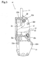
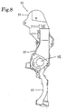
- Figs. 5 to 9 show the auxiliary machinery bracket 10.
- the auxiliary machinery bracket 10 is formed so as to be long vertically and can be sectioned into upper, middle and lower portions roughly.
- the upper portion is a flat plate 31 perpendicular to right-left direction having an arcuate upper edge.
- the middle and lower portions form walls 32, 33 perpendicular to front-rear direction.
- the middle wall 32 and the lower wall 33 jointly present a front view of a vertically long rectangular (Fig. 5)
- an oil pressure pump 11 for power steering On the right side of the upper flat plate 31 is attached an oil pressure pump 11 for power steering, on a front face of the middle wall 32 is attached an AC generator 12 and on a curved front face of the lower wall 33 is attached a compressor 13.
- a right end face of the middle wall 32 constitutes a contact face for attaching a water pump 14.
- an enclosing wall 35 and a cylindrical wall 36 corresponding to the enclosing wall 21 and the cylindrical wall 23 on the front wall of the cylinder block 3 (Fig. 6).
- End faces of the walls 35, 36 constitutes a contact face 35a to be connected with the enclosing wall 21 and the cylindrical wall 23 of the cylinder block 3 through a packing 37.
- a portion surrounded by the enclosing wall 35 and the cylindrical wall 36 constitutes the breather chamber 20, and the interior of the cylindrical wall 36 constitutes the discharge side cooling water passage 24 together with the interior of the cylindrical wall 23 on the side of the cylinder block 3.
- a gas outlet port 38a opening to the breather chamber 20
- a gas outlet hole 38 communicating with the gas outlet port 38a extends forward penetrating the middle wall 32
- a PCV valve 39 is fitted in the gas outlet hole 38 (Fig. 9).
- a circular suction side cooling water passage 40 penetrates a lower part of the middle wall 32 in right-left direction horizontally.
- a discharge side cooling water passage 41 is drilled from the right end face of the wall 32 to communicate with the discharge side cooling water passage 24 in the cylindrical wall 36.
- the suction side cooling water passage 40 is a circular hole extending in right-left direction
- the discharge side cooling water passage 41 has a right end opening elongated vertically and the sectional area of the passage 41 becomes gradually smaller toward the cylindrical wall 36 where the passage 41 is connected with the passage 24.
- a driven pulley 14b is projected from the pump case 14a.
- nuts 46 are screwed onto respective exposed ends of the stud bolts 46, and the upper three positions (attachment holes 35b, bolt holes 21b) and lower two positions (attachment holes 33a, bolt holes 2a) are tightened by bolts 47.
- Fig. 2 shows the engine attached with the auxiliary machinery bracket 10 in the manner as mentioned above.
- the water pump 14 On the right end face of the auxiliary machinery bracket 10 is attached the water pump 14 as shown by the dot-dash line.
- the oil pressure pump 11 is attached to the upper flat plate 31, the AC generator 12 is attached to the front face of the middle wall 32 and the compressor 13 is attached to the front face of the curved lower wall 33, as shown in Fig. 1.
- An endless belt 51 is wound round a drive pulley 7a fitted to the crankshaft, an idler pulley 50, a driven pulley 11a of the oil pressure pump 11, a driven pulley 12a of the AC generator 12, a driven pulley 14b of the water pump 14 and a driven pulley 13a of the compressor 13 so that the pulleys are driven altogether.
- the breather chamber 20 formed by attaching the auxiliary machinery bracket 10 on the wall of the cylinder block 3 communicates with the interior of the crankcase 2 through the blow-by gas introducing passage 26 formed on side of the cylinder block 3, so that blow-by gas leaking in the crank chamber is introduced into the breather chamber 20 through the blow-by gas introducing passage 26 together with fresh air (Fig. 4).
- Fig. 9 is a sectional view of the engine attached with the auxiliary machinery bracket 10 in which the part shown by cross hatches is the breather chamber 20.
- blow-by gas is separated into vapor and liquid, and separated oil component flows out into the cam chain chamber 28a through the oil recovery passage 27 opening at the lowest point of the breather chamber 20 to be recovered within the oil pan 6.
- the blow-by gas from which the oil component has been separated is guided from the gas outlet hole 38 to an outlet pipe (not shown) with a flow rate adjusted by the PCV valve 38, and sent to a suction chamber at downstream side of a throttle valve to be burned again.
- both the blow-by gas introducing passage 26 connecting the breather chamber 20 to the interior of the crankcase 2 and the oil recovery passage 27 connecting the breather chamber 20 to the interior of the oil pan 6 are formed in the wall of the cylinder block 3, it is possible to simplify the construction and reduce the cost. If the above-mentioned passages are formed in the auxiliary machinery bracket 10, the construction to connect the passages to the crankcase and the oil pan is complicated and a special attachment is necessary for sealing.
- the left side opening of the suction side cooling water passage 40 is connected with a cooling water circulation passage so as to communicating with a passage communicating with the radiator or a return passage from the engine by switching over a thermostat valve, Cooling water is introduced to the suction side cooling water passage 40 by the water pump 14.
- the cooling water sucked in the water pump 14 from the right end opening of the suction side cooling water passage 40 is discharged to the right end opening of the discharge side cooling water passage 41 and introduced into the water jacket 25 of the of the cylinder block 3 through the discharge side cooling water passage 41 and the discharge side cooling water passage 24 (Fig. 9).
- the aforementioned thermostat valve opens a bypass passage so that cooling water heated by the engine is sent directly to the suction side cooling water passage 40 neighboring the breather chamber 20 Therefore, the breather chamber 20 can be warmed and condensation of vapor in the breather chamber 20 can be prevented.
- suction side cooling water passage 40 and the discharge side cooling water passages 41, 24 are formed swelling in the breather chamber 20, heating effect is high and the breather chamber 20 can be warmed efficiently and quickly.
- cooling water cooled by the radiator is sent to the suction side cooling water passage 40 and the discharge side cooling water passages 41, 24 to cool the breather chamber 20 for hastening vapor-liquid separation of blow-by gas.
- the breather chamber 20 is formed between the cylinder block 3 and the auxiliary machinery bracket 10 utilizing the bracket 10 and the suction side cooling water passage 40 and the discharge side cooling water passages 41, 24 are formed integrally with the breather chamber 20, high space efficiency is obtained by utilizing a space between the cylinder block 3 and the auxiliary machinery, and enlargement of the whole internal combustion engine 1 can be avoided.
- cooling water passages can be formed in the breather chamber easily, and it is possible to reduce the number of parts and facilitate the assembling.
- the auxiliary machinery bracket 10 is a synthetic bracket which supports the oil pressure pump 11, the AC generator 12, the compressor 13 and the water pump 14 collectively, so that the auxiliary machines can be attached with a small number of attachment parts, enlargement of the whole international combustion engine can be prevented, the assembling work is easy and the cost can be reduced.
- the present invention can be applied to an internal combustion engine having auxiliary machinery attached to a side wall of a cylinder block by means of a reinforcement bracket.
Landscapes
- Engineering & Computer Science (AREA)
- Mechanical Engineering (AREA)
- General Engineering & Computer Science (AREA)
- Lubrication Details And Ventilation Of Internal Combustion Engines (AREA)
- Cylinder Crankcases Of Internal Combustion Engines (AREA)
Abstract
Description
Claims (5)
- A breather chamber structure of an internal combustion engine having auxiliary machinery attached to a side wall of a cylinder block by means of an auxiliary machinery bracket, comprising:a breather chamber formed by said side wall of the cylinder block and said auxiliary machinery bracket between said side wall and said bracket; anda cooling water passage formed on at least one of said side wall of the cylinder block and said auxiliary machinery bracket swelling in said breather chamber.
- A breather chamber structure of an internal combustion engine as claimed in claim 1, wherein said cooling water passage is formed on said auxiliary machinery bracket, and a water pump is attached to said auxiliary machinery bracket for circulating cooling water through said cooling water passage.
- A breather chamber structure of an internal combustion engine as claimed in claim 2, wherein a suction side cooling water passage connected to a suction side of said water pump and a discharge side cooling water passage connected to a discharge side of said water pump are formed on a breather chamber portion of said auxiliary machinery bracket.
- A breather chamber structure of an internal combustion engine as claimed in claim 1, 2 or 3, wherein a blow-by gas passage connecting an interior of a crankcase with said breather chamber is formed in said wall of the cylinder block, and an oil recovery passage for recovering oil separated from the blow-by gas in said breather chamber into an oil pan is formed in a lower part of said side wall of said cylinder block.
- A breather chamber structure of an internal combustion engine as claimed in claim 1, 2 3 or 4, wherein said auxiliary machinery bracket is a synthetic bracket for attaching more than two auxiliary machines.
Applications Claiming Priority (3)
| Application Number | Priority Date | Filing Date | Title |
|---|---|---|---|
| JP25077899A JP3423649B2 (en) | 1999-09-03 | 1999-09-03 | Breather chamber structure of internal combustion engine |
| JP25077899 | 1999-09-03 | ||
| PCT/JP2000/005948 WO2001018364A1 (en) | 1999-09-03 | 2000-09-01 | Breather chamber structure of internal combustion engine |
Publications (3)
| Publication Number | Publication Date |
|---|---|
| EP1130225A1 true EP1130225A1 (en) | 2001-09-05 |
| EP1130225A4 EP1130225A4 (en) | 2004-06-16 |
| EP1130225B1 EP1130225B1 (en) | 2007-08-15 |
Family
ID=17212914
Family Applications (1)
| Application Number | Title | Priority Date | Filing Date |
|---|---|---|---|
| EP00956869A Expired - Lifetime EP1130225B1 (en) | 1999-09-03 | 2000-09-01 | Breather chamber structure of internal combustion engine |
Country Status (10)
| Country | Link |
|---|---|
| US (1) | US6415778B1 (en) |
| EP (1) | EP1130225B1 (en) |
| JP (1) | JP3423649B2 (en) |
| CN (1) | CN1110618C (en) |
| AU (1) | AU762920B2 (en) |
| BR (1) | BR0007191B1 (en) |
| CA (1) | CA2350244C (en) |
| DE (1) | DE60035950T2 (en) |
| TW (1) | TW544488B (en) |
| WO (1) | WO2001018364A1 (en) |
Cited By (8)
| Publication number | Priority date | Publication date | Assignee | Title |
|---|---|---|---|---|
| US7185615B2 (en) | 2002-04-17 | 2007-03-06 | Honda Giken Kogyo Kabushiki Kaisha | Variable stroke engine |
| FR2913249A1 (en) * | 2007-03-01 | 2008-09-05 | Peugeot Citroen Automobiles Sa | METHOD AND DEVICE FOR REHAUTING CARTER GAS AND DECANTATION CHAMBER FOR CARTER GAS |
| WO2009081260A1 (en) * | 2007-12-21 | 2009-07-02 | Toyota Jidosha Kabushiki Kaisha | Oil separation device |
| FR2973071A1 (en) * | 2011-03-21 | 2012-09-28 | Renault Sas | Oil decanter for separating liquid and gas phases of blow-by gas in e.g. positive-ignition engine, has casing internally defining cooling channel for passage of coolant, where channel is hermetically isolated from decantation chamber |
| FR2989994A1 (en) * | 2012-04-27 | 2013-11-01 | Peugeot Citroen Automobiles Sa | Accessory support for supporting e.g. alternator, by combustion engine in power plant, has channel intended to be connected to lubrication circuit of engine, where channel includes bend for orientation of oil pressure sensor along engine |
| FR2991377A1 (en) * | 2012-06-04 | 2013-12-06 | Peugeot Citroen Automobiles Sa | Thermal engine for car, has engine support insert fixed to one end of cylinder casing, and gas passage connecting lower volume of casing to upper volume of cylinder head, where gas passage extends partly in engine support insert |
| EP2865934A1 (en) * | 2013-10-28 | 2015-04-29 | Aisin Seiki Kabushiki Kaisha | Internal combustion engine and separator structure thereof |
| DE102013021983A1 (en) * | 2013-12-20 | 2015-06-25 | Mtu Friedrichshafen Gmbh | A method for improving the cold start performance of an internal combustion engine and crankcase ventilation device thereto |
Families Citing this family (7)
| Publication number | Priority date | Publication date | Assignee | Title |
|---|---|---|---|---|
| JP6299298B2 (en) * | 2013-11-07 | 2018-03-28 | アイシン精機株式会社 | Internal combustion engine and internal combustion engine separator structure |
| JP6206086B2 (en) * | 2013-10-28 | 2017-10-04 | アイシン精機株式会社 | Internal combustion engine |
| JP6252144B2 (en) | 2013-12-06 | 2017-12-27 | スズキ株式会社 | Blow-by gas processing device for internal combustion engine |
| JP6329802B2 (en) * | 2014-03-31 | 2018-05-23 | ダイハツ工業株式会社 | Internal combustion engine |
| JP6678543B2 (en) * | 2016-09-02 | 2020-04-08 | 株式会社クボタ | Blow-by gas heating device |
| JP6315045B2 (en) | 2016-09-06 | 2018-04-25 | マツダ株式会社 | Water-reduction structure for vehicle engines |
| JP7363350B2 (en) * | 2019-10-17 | 2023-10-18 | スズキ株式会社 | Engine auxiliary equipment mounting structure |
Family Cites Families (12)
| Publication number | Priority date | Publication date | Assignee | Title |
|---|---|---|---|---|
| JPS57181912A (en) * | 1981-05-02 | 1982-11-09 | Honda Motor Co Ltd | Heater for lubricating oil of internal combustion engine |
| US4541399A (en) * | 1983-03-03 | 1985-09-17 | Mazda Motor Corporation | Breather arrangement for internal combustion engine |
| JPH041031Y2 (en) * | 1984-12-18 | 1992-01-14 | ||
| JPS63160309U (en) * | 1987-04-09 | 1988-10-20 | ||
| JPH0627779Y2 (en) * | 1987-12-22 | 1994-07-27 | 本田技研工業株式会社 | Oil mist separation device in blow-by gas extraction device for multi-cylinder engine |
| JP2690968B2 (en) * | 1988-09-30 | 1997-12-17 | ヤマハ発動機株式会社 | V-type engine cooling system |
| JPH0299212U (en) * | 1989-01-25 | 1990-08-07 | ||
| JP2888383B2 (en) | 1991-05-17 | 1999-05-10 | ヤマハ発動機株式会社 | Breather chamber arrangement structure of internal combustion engine |
| JP3069273B2 (en) * | 1995-08-09 | 2000-07-24 | ダイハツ工業株式会社 | Auxiliary equipment for internal combustion engine |
| DE19541374C2 (en) * | 1995-11-07 | 1999-08-05 | Man Nutzfahrzeuge Ag | Vent valve for a crankcase of an internal combustion engine |
| DE19736039B4 (en) * | 1997-08-20 | 2018-01-11 | Man Truck & Bus Ag | Internal combustion engine with an oil module |
| US5937837A (en) * | 1997-12-09 | 1999-08-17 | Caterpillar Inc. | Crankcase blowby disposal system |
-
1999
- 1999-09-03 JP JP25077899A patent/JP3423649B2/en not_active Expired - Fee Related
-
2000
- 2000-09-01 WO PCT/JP2000/005948 patent/WO2001018364A1/en not_active Ceased
- 2000-09-01 CA CA002350244A patent/CA2350244C/en not_active Expired - Fee Related
- 2000-09-01 DE DE60035950T patent/DE60035950T2/en not_active Expired - Lifetime
- 2000-09-01 US US09/807,957 patent/US6415778B1/en not_active Expired - Lifetime
- 2000-09-01 CN CN00801883A patent/CN1110618C/en not_active Expired - Fee Related
- 2000-09-01 AU AU68678/00A patent/AU762920B2/en not_active Ceased
- 2000-09-01 BR BRPI0007191-9A patent/BR0007191B1/en not_active IP Right Cessation
- 2000-09-01 EP EP00956869A patent/EP1130225B1/en not_active Expired - Lifetime
- 2000-09-02 TW TW089118013A patent/TW544488B/en not_active IP Right Cessation
Cited By (12)
| Publication number | Priority date | Publication date | Assignee | Title |
|---|---|---|---|---|
| US7185615B2 (en) | 2002-04-17 | 2007-03-06 | Honda Giken Kogyo Kabushiki Kaisha | Variable stroke engine |
| FR2913249A1 (en) * | 2007-03-01 | 2008-09-05 | Peugeot Citroen Automobiles Sa | METHOD AND DEVICE FOR REHAUTING CARTER GAS AND DECANTATION CHAMBER FOR CARTER GAS |
| EP1965045A3 (en) * | 2007-03-01 | 2010-10-13 | Peugeot Citroën Automobiles Sa | Method and device for reheating crankcase emissions and gravity collector designed for crankcase emissions |
| WO2009081260A1 (en) * | 2007-12-21 | 2009-07-02 | Toyota Jidosha Kabushiki Kaisha | Oil separation device |
| FR2973071A1 (en) * | 2011-03-21 | 2012-09-28 | Renault Sas | Oil decanter for separating liquid and gas phases of blow-by gas in e.g. positive-ignition engine, has casing internally defining cooling channel for passage of coolant, where channel is hermetically isolated from decantation chamber |
| FR2989994A1 (en) * | 2012-04-27 | 2013-11-01 | Peugeot Citroen Automobiles Sa | Accessory support for supporting e.g. alternator, by combustion engine in power plant, has channel intended to be connected to lubrication circuit of engine, where channel includes bend for orientation of oil pressure sensor along engine |
| FR2991377A1 (en) * | 2012-06-04 | 2013-12-06 | Peugeot Citroen Automobiles Sa | Thermal engine for car, has engine support insert fixed to one end of cylinder casing, and gas passage connecting lower volume of casing to upper volume of cylinder head, where gas passage extends partly in engine support insert |
| EP2865934A1 (en) * | 2013-10-28 | 2015-04-29 | Aisin Seiki Kabushiki Kaisha | Internal combustion engine and separator structure thereof |
| US9581061B2 (en) | 2013-10-28 | 2017-02-28 | Aisin Seiki Kabushiki Kaisha | Internal combustion engine and separator structure thereof |
| DE102013021983A1 (en) * | 2013-12-20 | 2015-06-25 | Mtu Friedrichshafen Gmbh | A method for improving the cold start performance of an internal combustion engine and crankcase ventilation device thereto |
| DE102013021983B4 (en) * | 2013-12-20 | 2016-03-24 | Mtu Friedrichshafen Gmbh | A method for improving the cold start property of an internal combustion engine and crankcase ventilation device thereto |
| US10184444B2 (en) | 2013-12-20 | 2019-01-22 | Mtu Friedrichshafen Gmbh | Method for improving the cold start capacity of an internal combustion engine, and crankcase ventilating device for this purpose |
Also Published As
| Publication number | Publication date |
|---|---|
| EP1130225B1 (en) | 2007-08-15 |
| EP1130225A4 (en) | 2004-06-16 |
| CA2350244C (en) | 2005-05-17 |
| AU762920B2 (en) | 2003-07-10 |
| DE60035950D1 (en) | 2007-09-27 |
| AU6867800A (en) | 2001-04-10 |
| US6415778B1 (en) | 2002-07-09 |
| JP3423649B2 (en) | 2003-07-07 |
| BR0007191A (en) | 2001-08-21 |
| TW544488B (en) | 2003-08-01 |
| BR0007191B1 (en) | 2009-05-05 |
| CA2350244A1 (en) | 2001-03-15 |
| DE60035950T2 (en) | 2008-05-08 |
| WO2001018364A1 (en) | 2001-03-15 |
| CN1321217A (en) | 2001-11-07 |
| JP2001073738A (en) | 2001-03-21 |
| CN1110618C (en) | 2003-06-04 |
Similar Documents
| Publication | Publication Date | Title |
|---|---|---|
| CA2350244C (en) | Breather chamber structure of an internal combustion engine | |
| US11614019B2 (en) | Engine | |
| JPH09189225A (en) | Cooling device for outboard engine | |
| JP3907903B2 (en) | Cooling water circulation structure of internal combustion engine | |
| CN100497899C (en) | Outboard motor equiped with water-cooled engine | |
| JPH06280709A (en) | Water-cooled engine | |
| JP4342283B2 (en) | Breather structure of internal combustion engine | |
| JPH1054296A (en) | Cooling system for 4-cycle engine | |
| JP3858348B2 (en) | Outboard motor exhaust system | |
| CA2356233C (en) | Outboard motor | |
| KR20050043007A (en) | Crankcase having blowby gas passage and oil drain passage | |
| EP0653553A2 (en) | Cooling system for an internal combustion engine | |
| CN1497141A (en) | Water-cooled vertical engines, outboard-mounted motors equipped with water-cooled vertical engines, and outboard-mounted motors | |
| JPH04203325A (en) | Motorcycle | |
| JP3182867B2 (en) | Outboard motor cooling system | |
| US4836152A (en) | Exhaust heated crankcase for 2-cycle marine engine | |
| JP4367679B2 (en) | Outboard motor | |
| US6279515B1 (en) | Coolant pump chamber cover with ignition module supports | |
| JPH09254884A (en) | Cowling air duct structure of outboard motor | |
| JP2515112B2 (en) | Water-cooled 2-cycle internal combustion engine | |
| JP2001241356A (en) | Cylinder block structure of 4-cycle multi-cylinder engine | |
| JP3849840B2 (en) | Cooling passage structure of internal combustion engine for vehicle | |
| JP2829595B2 (en) | Engine unit for vehicle | |
| JPH09189260A (en) | Head cover device of outboard engine | |
| JPH08109849A (en) | Cylinder head structure for outboard motor with four-stroke engine |
Legal Events
| Date | Code | Title | Description |
|---|---|---|---|
| PUAI | Public reference made under article 153(3) epc to a published international application that has entered the european phase |
Free format text: ORIGINAL CODE: 0009012 |
|
| 17P | Request for examination filed |
Effective date: 20010503 |
|
| AK | Designated contracting states |
Kind code of ref document: A1 Designated state(s): AT BE CH CY DE DK ES FI FR GB GR IE IT LI LU MC NL PT SE |
|
| RBV | Designated contracting states (corrected) |
Designated state(s): DE FR GB IT |
|
| A4 | Supplementary search report drawn up and despatched |
Effective date: 20040507 |
|
| RIC1 | Information provided on ipc code assigned before grant |
Ipc: 7F 01M 5/02 B Ipc: 7F 01M 13/00 B Ipc: 7F 01M 13/04 A |
|
| GRAP | Despatch of communication of intention to grant a patent |
Free format text: ORIGINAL CODE: EPIDOSNIGR1 |
|
| GRAS | Grant fee paid |
Free format text: ORIGINAL CODE: EPIDOSNIGR3 |
|
| GRAA | (expected) grant |
Free format text: ORIGINAL CODE: 0009210 |
|
| AK | Designated contracting states |
Kind code of ref document: B1 Designated state(s): DE FR GB IT |
|
| REG | Reference to a national code |
Ref country code: GB Ref legal event code: FG4D |
|
| REF | Corresponds to: |
Ref document number: 60035950 Country of ref document: DE Date of ref document: 20070927 Kind code of ref document: P |
|
| ET | Fr: translation filed | ||
| PLBE | No opposition filed within time limit |
Free format text: ORIGINAL CODE: 0009261 |
|
| STAA | Information on the status of an ep patent application or granted ep patent |
Free format text: STATUS: NO OPPOSITION FILED WITHIN TIME LIMIT |
|
| 26N | No opposition filed |
Effective date: 20080516 |
|
| PGFP | Annual fee paid to national office [announced via postgrant information from national office to epo] |
Ref country code: GB Payment date: 20110831 Year of fee payment: 12 |
|
| PGFP | Annual fee paid to national office [announced via postgrant information from national office to epo] |
Ref country code: IT Payment date: 20110914 Year of fee payment: 12 |
|
| REG | Reference to a national code |
Ref country code: DE Ref legal event code: R084 Ref document number: 60035950 Country of ref document: DE Effective date: 20120523 |
|
| PGFP | Annual fee paid to national office [announced via postgrant information from national office to epo] |
Ref country code: FR Payment date: 20120926 Year of fee payment: 13 |
|
| GBPC | Gb: european patent ceased through non-payment of renewal fee |
Effective date: 20120901 |
|
| PG25 | Lapsed in a contracting state [announced via postgrant information from national office to epo] |
Ref country code: GB Free format text: LAPSE BECAUSE OF NON-PAYMENT OF DUE FEES Effective date: 20120901 |
|
| PG25 | Lapsed in a contracting state [announced via postgrant information from national office to epo] |
Ref country code: IT Free format text: LAPSE BECAUSE OF NON-PAYMENT OF DUE FEES Effective date: 20120901 |
|
| PGFP | Annual fee paid to national office [announced via postgrant information from national office to epo] |
Ref country code: DE Payment date: 20130829 Year of fee payment: 14 |
|
| REG | Reference to a national code |
Ref country code: FR Ref legal event code: ST Effective date: 20140530 |
|
| PG25 | Lapsed in a contracting state [announced via postgrant information from national office to epo] |
Ref country code: FR Free format text: LAPSE BECAUSE OF NON-PAYMENT OF DUE FEES Effective date: 20130930 |
|
| REG | Reference to a national code |
Ref country code: DE Ref legal event code: R119 Ref document number: 60035950 Country of ref document: DE |
|
| REG | Reference to a national code |
Ref country code: DE Ref legal event code: R119 Ref document number: 60035950 Country of ref document: DE Effective date: 20150401 |
|
| PG25 | Lapsed in a contracting state [announced via postgrant information from national office to epo] |
Ref country code: DE Free format text: LAPSE BECAUSE OF NON-PAYMENT OF DUE FEES Effective date: 20150401 |