EP1130219A1 - Turbine engine with sealing means between panels - Google Patents
Turbine engine with sealing means between panels Download PDFInfo
- Publication number
- EP1130219A1 EP1130219A1 EP00104346A EP00104346A EP1130219A1 EP 1130219 A1 EP1130219 A1 EP 1130219A1 EP 00104346 A EP00104346 A EP 00104346A EP 00104346 A EP00104346 A EP 00104346A EP 1130219 A1 EP1130219 A1 EP 1130219A1
- Authority
- EP
- European Patent Office
- Prior art keywords
- sealing element
- turbine system
- turbine
- plate elements
- adjacent
- Prior art date
- Legal status (The legal status is an assumption and is not a legal conclusion. Google has not performed a legal analysis and makes no representation as to the accuracy of the status listed.)
- Withdrawn
Links
Images

Classifications
-
- F—MECHANICAL ENGINEERING; LIGHTING; HEATING; WEAPONS; BLASTING
- F01—MACHINES OR ENGINES IN GENERAL; ENGINE PLANTS IN GENERAL; STEAM ENGINES
- F01D—NON-POSITIVE DISPLACEMENT MACHINES OR ENGINES, e.g. STEAM TURBINES
- F01D11/00—Preventing or minimising internal leakage of working-fluid, e.g. between stages
- F01D11/005—Sealing means between non relatively rotating elements
-
- F—MECHANICAL ENGINEERING; LIGHTING; HEATING; WEAPONS; BLASTING
- F23—COMBUSTION APPARATUS; COMBUSTION PROCESSES
- F23R—GENERATING COMBUSTION PRODUCTS OF HIGH PRESSURE OR HIGH VELOCITY, e.g. GAS-TURBINE COMBUSTION CHAMBERS
- F23R3/00—Continuous combustion chambers using liquid or gaseous fuel
- F23R3/002—Wall structures
-
- F—MECHANICAL ENGINEERING; LIGHTING; HEATING; WEAPONS; BLASTING
- F05—INDEXING SCHEMES RELATING TO ENGINES OR PUMPS IN VARIOUS SUBCLASSES OF CLASSES F01-F04
- F05D—INDEXING SCHEME FOR ASPECTS RELATING TO NON-POSITIVE-DISPLACEMENT MACHINES OR ENGINES, GAS-TURBINES OR JET-PROPULSION PLANTS
- F05D2260/00—Function
- F05D2260/20—Heat transfer, e.g. cooling
- F05D2260/205—Cooling fluid recirculation, i.e. after cooling one or more components is the cooling fluid recovered and used elsewhere for other purposes
-
- F—MECHANICAL ENGINEERING; LIGHTING; HEATING; WEAPONS; BLASTING
- F05—INDEXING SCHEMES RELATING TO ENGINES OR PUMPS IN VARIOUS SUBCLASSES OF CLASSES F01-F04
- F05D—INDEXING SCHEME FOR ASPECTS RELATING TO NON-POSITIVE-DISPLACEMENT MACHINES OR ENGINES, GAS-TURBINES OR JET-PROPULSION PLANTS
- F05D2260/00—Function
- F05D2260/20—Heat transfer, e.g. cooling
- F05D2260/232—Heat transfer, e.g. cooling characterized by the cooling medium
- F05D2260/2322—Heat transfer, e.g. cooling characterized by the cooling medium steam
-
- F—MECHANICAL ENGINEERING; LIGHTING; HEATING; WEAPONS; BLASTING
- F23—COMBUSTION APPARATUS; COMBUSTION PROCESSES
- F23M—CASINGS, LININGS, WALLS OR DOORS SPECIALLY ADAPTED FOR COMBUSTION CHAMBERS, e.g. FIREBRIDGES; DEVICES FOR DEFLECTING AIR, FLAMES OR COMBUSTION PRODUCTS IN COMBUSTION CHAMBERS; SAFETY ARRANGEMENTS SPECIALLY ADAPTED FOR COMBUSTION APPARATUS; DETAILS OF COMBUSTION CHAMBERS, NOT OTHERWISE PROVIDED FOR
- F23M2900/00—Special features of, or arrangements for combustion chambers
- F23M2900/05005—Sealing means between wall tiles or panels
-
- F—MECHANICAL ENGINEERING; LIGHTING; HEATING; WEAPONS; BLASTING
- F23—COMBUSTION APPARATUS; COMBUSTION PROCESSES
- F23R—GENERATING COMBUSTION PRODUCTS OF HIGH PRESSURE OR HIGH VELOCITY, e.g. GAS-TURBINE COMBUSTION CHAMBERS
- F23R2900/00—Special features of, or arrangements for continuous combustion chambers; Combustion processes therefor
- F23R2900/00012—Details of sealing devices
-
- F—MECHANICAL ENGINEERING; LIGHTING; HEATING; WEAPONS; BLASTING
- F23—COMBUSTION APPARATUS; COMBUSTION PROCESSES
- F23R—GENERATING COMBUSTION PRODUCTS OF HIGH PRESSURE OR HIGH VELOCITY, e.g. GAS-TURBINE COMBUSTION CHAMBERS
- F23R2900/00—Special features of, or arrangements for continuous combustion chambers; Combustion processes therefor
- F23R2900/03044—Impingement cooled combustion chamber walls or subassemblies
Definitions
- the invention relates to a turbine system, in particular one Gas turbine plant.
- a plant is called a gas turbine plant understood that a combustion chamber and one of the combustion chamber subordinate turbine designated as a gas turbine.
- a combustion chamber burns a fuel gas in a gas space, and the hot gas generated thereby is fed to the turbine and flows through them.
- the flow path of the hot gas through the Turbine is also referred to below as a gas space.
- the turbine has fixed vanes that differ from extend radially outside into the gas space, as well as on a Runners designated shaft mounted blades that shovel on extend radially outward from the rotor. Longitudinal Looking at the turbine, the guide vanes and the grab The blades shovel into one another tooth-like.
- the turbine has in usually several turbine stages, with one in each stage Guide vane ring is arranged, i.e. several of the vanes are arranged side by side in the circumferential direction of the turbine.
- the individual guide vane rings are axial Direction sequentially arranged.
- the gas space is usually clad with panel elements. Are at the combustion chamber this is tiling, and in the turbine are the plate elements formed by so-called base plates of the individual guide vanes.
- the gas area of the combustion chamber and the turbine should be as possible be tight. Therefore, there is little leakage loss between the individual plate elements. In particular should prevent leakage losses between two turbine stages become.
- As a result of the large temperature ranges in the gas space there is a problem that sealing stretches the individual Plate elements must take up and bridge without that the seal is significantly impaired. Reinforced this problem is caused by the fact that both the tiles as well the base plates of the guide vane are not at their edge areas are attached to adjacent plate elements so that the Plate edges are more or less free and a bend as a result are subject to thermal expansion.
- the tiles are usually attached in the middle and bend approximately spherically under thermal stress.
- a seal must therefore - also because of the axial direction conical design of the combustion chamber and the turbine - both allow axial as well as radial mobility.
- the invention has for its object to provide a seal enable that overcomes the disadvantages described.
- a turbine system in particular gas turbine plant with a gas space
- the outside through adjacent plate elements is limited, each with a sealing element adjacent to each other Plate elements is assigned and this at their the Back sides facing away from the gas space are connected in a clamp-like manner.
- the main advantage here is in the bracket-like To see the design of the sealing element.
- the sealing element thus spans the two plate elements. With thermal The sealing element follows the plate elements without stretching to release a gap. The sealing by the sealing element is therefore largely unaffected by thermal expansion.
- the sealing element makes it possible to ensure expansion preferably a mobility of the plate elements both in the axial as well as in the radial direction.
- the sealing element is therefore both in the axial and in the radial direction especially elastic. In the axial direction becomes an expansion in the longitudinal direction of the turbine system and in the radial direction an expansion perpendicular understood to the longitudinal axis.
- the sealing element preferably has two legs that each in a groove of adjacent plate elements to grab. This makes it easy to manufacture enables fastening of the sealing elements to be realized.
- the groove preferably extends from the rear of the respective Plate element in this essentially radial inside.
- the legs therefore protrude radially outwards from the grooves.
- This configuration of the groove enables a simple one Manufacturing and in particular high accuracy, for example by grinding or eroding.
- the advantage of the arrangement on the back you can see that the groove in the No special one with regard to the problem of thermal expansions Form. Groove and sealing element can therefore can be adapted very precisely to one another, so that very little Leakage gaps can be achieved.
- the sealing element In order to assemble the plate elements in the turbine system a simple procedure is the sealing element preferably constructed in several parts.
- the legs of the multi-part preferably overlap Sealing element over a common circumferential length. This The circumferential length is large enough to prevent leaks largely avoided.
- the sealing element is U-shaped trained in both manufacturing and assembly technology is easy to implement.
- the sealing element expediently has this corrugated Structure in several directions so that it stretches in can take different directions.
- the sealing element is double S-shaped.
- the sealing element is between adjacent tiles of a combustion chamber arranged. So that will achieved a secure seal between the tiles, itself if they are spherical due to the thermal load to bend.
- the sealing element is between the base plates of adjacent guide vanes a turbine arranged, in particular between the Base plates of guide blades of neighboring turbine stages.
- the individual base plates are therefore in the axial or longitudinal direction the turbine via clamp-like sealing elements connected.
- the further sealing element preferably has a receiving area into which the plate elements extend.
- the sealing element is in cross section seen H-shaped.
- the basic idea of this Design is the reverse of a conventional sealing principle can be seen in which a sealing plate in corresponding front grooves of the foot plates is introduced. This requires namely usually a reinforcement of the edge of the Foot plates in the groove area. This is for good cooling of the Foot plates problematic because of the different Even cooling is difficult to achieve with material thicknesses and thermal stresses can occur.
- this sealing principle is now not the sealing plate inserted in the footplates, but the footplates are introduced into the sealing element. This eliminates the Need to reinforce the edge area of the footplate. The coolability is thus simplified and the base plate is cooled homogeneously in all areas, so that none thermal stresses occur.
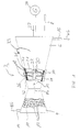
- a turbine system 1 comprises a turbine system 2, in particular one Gas turbine system of a turbo set for a power plant Power generation, a combustion chamber 4 and a turbine 6, the in the longitudinal or axial direction 8 of the turbine system 2 after the Brennkammmer 4 is arranged. Both the combustion chamber 4 and The turbine 6 is also cut open in a partial area shown. This is a look into the gas space 10 of the combustion chamber 4 and in the gas space 12 of the turbine 6.
- the combustion chamber 4 is connected to a gas supply 14 a fuel gas BG supplied, which is in the gas space 10 of the combustion chamber 4 is burned and forms a hot gas HG.
- the gas room 10 is formed with a plurality of plate elements Tiles 13 lined.
- the hot gas HG flows through the turbine 6 and leaves it as a cold gas KG via a Gas discharge 16.
- the hot gas HG is in the turbine 6 Guide vanes 18 and 20 blades. Doing so a shaft 22 driven on which the blades 20 are arranged are.
- the shaft 22 is connected to a generator 24.
- the blades 20 extend radially from the shaft 22 outward.
- the guide vanes 18 have a base plate 32 and an attached blade 21.
- the guide vanes 18 are each on the outside of the turbine via their base plates 32 6 attached to a so-called guide vane carrier 26 and extend radially into the gas space 12.
- the guide vanes 18 and the blades 20 tooth-like into each other.
- Several of the barrel scoops 20 as well the guide vanes 18 are combined to form a ring, each vane ring having a turbine stage represents.
- FIG 1 is the second turbine stage 28 and the third turbine stage 30 by way of example shown.
- the base plates 32 of the individual guide vanes 18 are also as the tiles 13 formed as plate elements that are against each other both in the axial direction 8 and in the circumferential direction 33 of the turbine 6 adjoin one another and the gas space 12 limit.
- the one marked with a circle in FIG. 1 The position is shown enlarged in FIGS. 2 to 4.
- the too these figures described seal between two in particular in the longitudinal direction 8 adjacent footplates 32 can also be used as a seal for the tiles 13 transferred to the combustion chamber 4.
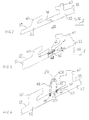
- the foot plates 32 according to FIGS. 2 to 4 have on their from Back side 39 facing away from gas space 12 each has a hooking element 40 on the foot plates 32 on the vane carrier 26 (see FIG. 1) are held.
- Each footplate 32 has typically two interlocking elements 40, which are different are designed and both an agility enable in the axial direction 8 as well as in the radial direction 36.
- FIG 3 shows a further conventional sealing arrangement a sealing plate 41, which in grooves 44 of the adjacent Foot plates 32 is inserted.
- the grooves 44 are there incorporated into the end faces 46 of the foot plates 32.
- she have an opening angle ⁇ of approximately 15 ° to a To allow mobility of the foot plates 32 in the radial direction 36.
- Also in this embodiment is between the Sealing plate 41 and the base plates 32 formed a leakage gap 38, the one with the stretch due to the thermal load varies.
- the foot plates 32 expand faster than the vane carrier 26 to which they are attached.
- the problems of the temperature dependence of the leakage gap 38 occurs in the novel design according to FIG 4 does not open. After that are in the area where the two Adjoin foot plates 32 with 39 grooves in the rear 44 incorporated, which essentially radially into the Extend footplates 32. It should be emphasized that the grooves 44 in accordance with FIG. 4 in contrast to those of FIG. 3 in parallel Have side walls 50. This enables a particularly simple one Making the grooves 44.
- a U-shaped sealing element 42A In the grooves 44 is a U-shaped sealing element 42A with its introduced both legs 52 and in particular attached. The attachment takes place, for example, by a clamping action or by welding.
- the sealing element 42A is special executed as a sheet metal element. His legs 52 extend essentially radially outwards, so that the arch 54 connecting the two legs 52 is spaced from the back 39. This stretched version enables elastic behavior of the sealing element 42A, i.e. it follows the thermal expansion of the foot plates 32. The thermal mobility of the foot plates 32 is thus ensured by the flexible or stretchable sealing element 42A. The mobility is therefore independent of the special design of the grooves 44, so that this very can be adapted to the legs 52. Between the leg 52 and the grooves 44 is therefore none or only a very small leakage gap 38 is formed, which is independent of the thermal stress on the foot plates 32.
- FIG. 5 is a sealing element 42B formed from two separate legs 52, which each have an arc 54 and over overlap a circumferential length L.
- the multi-part training of the sealing element 42B simplifies the assembly because, for example the individual legs 52 before assembly of the Guide vanes 18 simply into the corresponding grooves 44 of the respective foot plates 32 are attached and then these can be attached to the guide vane carrier 26.
- the common The circumferential length L is chosen to be as large as possible the leakage gap 38 formed between them for all temperature and to keep operating conditions low.
- a sealing element 42C In an alternative multi-part design of a sealing element 42C according to FIG. 6 is only one leg 52A provided with an arch 54, whereas the second leg 52B is a straight piece of sheet metal.
- the multi-part training Sealing elements 42B, 42C it is advantageous if the individual Leg 52 are pressed against each other in the assembled state and, for example, have a certain spring tension.
- FIG. 7 is a sealing element 42D with a corrugated Structure 58 provided that the simply designed arch 54th replaced according to Figures 4 to 6.
- This corrugated structure 58 preferably extends in several directions, in particular in both directions parallel to the foot plates 32.
- the legs 52 can also be corrugated.
- the Sealing element 42D is thus in the manner of a bellows trained and enables even large thermal expansions in several directions without the leakage gap 38 is enlarged.
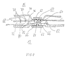
- the sealing elements 42A to 42D connect from assembly technology Base preferably the base plates 32 of guide vanes 18 adjacent turbine stages 28,30. To also in the circumferential direction 33 a good and easy to install seal to achieve is adjacent to each other in the circumferential direction 33 Guide vanes 18 of another guide vane ring Sealing element 60 is provided.
- the further sealing element 60 is preferably shown in FIG Cross section seen H-shaped and has two Longitudinal leg 62 on each other via a cross leg 64 are connected. Between the two longitudinal legs 62 are two receiving areas 65 separated from the cross leg 64 formed, into which the foot plates 32 extend. The margins 66 of the foot plates 32 are approximately perpendicular to the gas space 12 turned outwards and nestle immediately to the cross leg 64.
- This configuration with the receiving areas 65 for the foot plates 32 advantageously allows one over the entire base plate 32 homogeneous material thickness, so that a uniform cooling of the base plate 32 is guaranteed and Thermal stress in the foot plate 32 does not occur.
- Cooling system 68 To cool the foot plates 32, a closed one is used in particular Cooling system 68 provided with steam as the coolant, the is shown in detail in FIG 8.
- This closed Cooling system 68 has an inflow channel 70 and one Reverse flow channel 72.
- the inflow channel 70 is between one outer baffle 74 and a baffle plate 76, which arranged between the guide plate 74 and the foot plate 32 is.
- the baffle 76 has flow openings 78 which are designed in the manner of nozzles, so that this via the inflow channel 70 supplied coolant along the illustrated Arrows in the return flow passage 72. Because of the nozzle-like Operation of the flow openings 78 will High speed coolant against the rear 80 of the foot plate 32, so that an effective heat transfer realized between the coolant and the base plate 21 is.
- the baffle 76 is via support elements 82, for example in the form of welding spots or welding bars, against the footplate 32 supported and kept spaced.
- the baffle 70 is directly attached to the side edge 66 of the foot plate 32, in particular welded, and the baffle 68 is on Baffle plate 70 attached.
- a flow path 84 in the form of a leakage gap formed so that the outer space facing away from the gas space 12 86, for example, air via flow path 84 in can flow the gas space 12 and thus the sealing area, thus the sealing element 60 and the side edges 66 cools.
Abstract
Description
Die Erfindung betrifft eine Turbinenanlage, insbesondere eine Gasturbinenanlage.The invention relates to a turbine system, in particular one Gas turbine plant.
Unter einer Gasturbinenanlage wird im Folgenden eine Anlage verstanden, die eine Brennkammer und eine der Brennkammer nachgeordnete als Gasturbine-bezeichnete Turbine umfasst. In der Brennkammer wird ein Brenngas in einem Gasraum verbrannt, und das dabei erzeugte Heißgas wird der Turbine zugeführt und durchströmt diese. Der Strömungsweg des Heißgases durch die Turbine wird im Folgenden ebenfalls als Gasraum bezeichnet. Die Turbine weist feststehende Leitschaufeln, die sich von außen radial in den Gasraum erstrecken, sowie auf einer als Läufer bezeichneten Welle angebrachte Lauf schaufeln auf, die sich vom Läufer radial nach außen erstrecken. In Längsrichtung der Turbine betrachtet greifen die Leitschaufeln und die Lauf schaufeln zahnartig ineinander ein. Die Turbine hat in der Regel mehrere Turbinenstufen, wobei in jeder Stufe ein Leitschaufelkranz angeordnet ist, d.h. mehrere der Leitschaufeln sind in Umfangsrichtung der Turbine nebeneinander angeordnet. Die einzelnen Leitschaufelkränze sind in axialer Richtung aufeinanderfolgend angeordnet. Sowohl bei der Brennkammer als auch bei der Turbine ist der Gasraum üblicherweise mit Plattenelementen verkleidet. Bei der Brennkammer sind dies Kacheln, und bei der Turbine sind die Plattenelemente durch sogenannte Fußplatten der einzelnen Leitschaufeln gebildet.In the following, a plant is called a gas turbine plant understood that a combustion chamber and one of the combustion chamber subordinate turbine designated as a gas turbine. In the combustion chamber burns a fuel gas in a gas space, and the hot gas generated thereby is fed to the turbine and flows through them. The flow path of the hot gas through the Turbine is also referred to below as a gas space. The turbine has fixed vanes that differ from extend radially outside into the gas space, as well as on a Runners designated shaft mounted blades that shovel on extend radially outward from the rotor. Longitudinal Looking at the turbine, the guide vanes and the grab The blades shovel into one another tooth-like. The turbine has in usually several turbine stages, with one in each stage Guide vane ring is arranged, i.e. several of the vanes are arranged side by side in the circumferential direction of the turbine. The individual guide vane rings are axial Direction sequentially arranged. Both in the combustion chamber as well as in the turbine, the gas space is usually clad with panel elements. Are at the combustion chamber this is tiling, and in the turbine are the plate elements formed by so-called base plates of the individual guide vanes.
Der Gasbereich der Brennkammer sowie der Turbine soll möglichst dicht sein. Daher werden geringe Leckageverluste zwischen den einzelnen Plattenelementen angestrebt. Insbesondere sollen Leckageverluste zwischen zwei Turbinenstufen verhindert werden. Infolge der großen Temperaturspannen im Gasraum besteht das Problem, dass eine Abdichtung Dehnungen der einzelnen Plattenelemente aufnehmen und überbrücken muss, ohne dass die Abdichtung wesentlich beeinträchtigt wird. Verstärkt wird dieses Problem dadurch, dass sowohl die Kacheln als auch die Fußplatten der Leitschaufel nicht an ihren Randbereichen zu benachbarten Plattenelementen befestigt sind, so dass die Plattenränder mehr oder wenig frei sind und eine Biegung infolge einer thermischen Ausdehnung unterliegen. Die Kacheln sind beispielsweise in der Regel in ihrer Mitte befestigt und verbiegen sich bei thermischer Belastung etwa kugelförmig. Eine Abdichtung muss daher - auch wegen der in Axialrichtung konischen Ausbildung der Brennkammer und der Turbine - sowohl eine axiale als auch eine radiale Beweglichkeit zulassen.The gas area of the combustion chamber and the turbine should be as possible be tight. Therefore, there is little leakage loss between the individual plate elements. In particular should prevent leakage losses between two turbine stages become. As a result of the large temperature ranges in the gas space there is a problem that sealing stretches the individual Plate elements must take up and bridge without that the seal is significantly impaired. Reinforced this problem is caused by the fact that both the tiles as well the base plates of the guide vane are not at their edge areas are attached to adjacent plate elements so that the Plate edges are more or less free and a bend as a result are subject to thermal expansion. The tiles are usually attached in the middle and bend approximately spherically under thermal stress. A seal must therefore - also because of the axial direction conical design of the combustion chamber and the turbine - both allow axial as well as radial mobility.
Im Bereich der Turbine sind bei einer herkömmlichen Abdichtung die Fußplatten mit einer Nut an ihrer Stirnseite versehen, wobei in die Nuten zweier Fußplatten von Leitschaufeln benachbarter Turbinenstufen ein Dichtblech eingelegt ist. Bei den stirnseitigen Nuten wird die axial-radiale Beweglichkeit der Fußplatten dadurch erzielt, dass die Nuten schräge Seitenwände aufweisen. Derartige Nuten sind allerdings herstellungstechnisch sehr aufwendig. Zudem ist eine derartige Dichtung relativ undicht, da ein unterschiedlich schnelles Wärmeausdehnungsverhalten der Fußplatten und des sogenannten Turbinenleitschaufelträgers, an dem sie befestigt sind, zu berücksichtigen ist. Beim Anfahren der Turbine dehnen sich nämlich die Fußplatten schneller aus, so dass ein Leckagespalt zwischen den Fußplatten zunächst verschlossen wird. Der Leckagespalt öffnet sich wieder, wenn der Turbinenleitschaufelträger sich der Temperatur entsprechend gedehnt hat.In the area of the turbine there is a conventional seal provide the footplates with a groove on their face, being in the grooves of two base plates of guide vanes A sealing plate is inserted in adjacent turbine stages. At The grooves on the end face become axial-radial mobility the footplates achieved by making the grooves sloping side walls exhibit. Such grooves, however, are manufacturing technology very complex. Such a seal is also relatively leaky, because the thermal expansion behavior varies the base plates and the so-called turbine guide vane carrier, to which they are attached is. This is because when the turbine starts up, it expands the footplates out faster, leaving a leakage gap is initially closed between the foot plates. The leakage gap opens again when the turbine vane carrier has expanded according to the temperature.
Bei den Kacheln in der Brennkammer tritt zusätzlich das Problem auf, dass aufgrund ihrer kugelförmigen Verbiegung ein solches Dichtblech unter Umständen bis zum Versagen auf Scherung belastet wird.The problem also arises with the tiles in the combustion chamber on that due to their spherical bending such a sealing plate may fail until shear failure is charged.
Der Erfindung liegt die Aufgabe zugrunde, eine Abdichtung zu ermöglichen, die die beschriebenen Nachteile überwindet. The invention has for its object to provide a seal enable that overcomes the disadvantages described.
Die Aufgabe wird gemäß der Erfindung gelöst durch eine Turbinenanlage, insbesondere Gasturbinenanlage, mit einem Gasraum, der nach außen über aneinander angrenzende Plattenelemente begrenzt ist, wobei jeweils ein Dichtelement einander benachbarten Plattenelementen zugeordnet ist und diese an ihren dem Gasraum abgewandten Rückseiten klammerartig miteinander verbindet.The object is achieved according to the invention by a turbine system, in particular gas turbine plant with a gas space, the outside through adjacent plate elements is limited, each with a sealing element adjacent to each other Plate elements is assigned and this at their the Back sides facing away from the gas space are connected in a clamp-like manner.
Der wesentliche Vorteil ist hierbei in der klammerartigen Ausgestaltung des Dichtelements zu sehen. Das Dichtelement überspannt also die beiden Plattenelemente. Bei thermischen Dehnungen folgt das Dichtelement den Plattenelementen ohne einen Spalt freizugeben. Die Abdichtung durch das Dichtelement ist daher von thermischen Dehnungen weitgehend unbeeinflusst.The main advantage here is in the bracket-like To see the design of the sealing element. The sealing element thus spans the two plate elements. With thermal The sealing element follows the plate elements without stretching to release a gap. The sealing by the sealing element is therefore largely unaffected by thermal expansion.
Um eine möglichst gute Abdichtung auch bei allseitigen thermischen Dehnungen zu gewährleisten, ermöglicht das Dichtelement vorzugsweise eine Beweglichkeit der Plattenelemente sowohl in axialer als auch in radialer Richtung. Das Dichtelement ist daher sowohl in axialer als auch in radialer Richtung insbesondere elastisch ausgebildet. Unter axialer Richtung wird hierbei eine Ausdehnung in Längsrichtung der Turbinenanlage und unter radialer Richtung eine Ausdehnung senkrecht zu der Längsachse verstanden.To ensure the best possible seal even with all-round thermal The sealing element makes it possible to ensure expansion preferably a mobility of the plate elements both in the axial as well as in the radial direction. The sealing element is therefore both in the axial and in the radial direction especially elastic. In the axial direction becomes an expansion in the longitudinal direction of the turbine system and in the radial direction an expansion perpendicular understood to the longitudinal axis.
Vorzugsweise weist das Dichtelement zwei Schenkel auf, die jeweils in eine Nut von einander benachbarten Plattenelementen greifen. Dadurch ist eine herstellungstechnisch einfach zu verwirklichende Befestigung der Dichtelemente ermöglicht.The sealing element preferably has two legs that each in a groove of adjacent plate elements to grab. This makes it easy to manufacture enables fastening of the sealing elements to be realized.
Vorzugsweise erstreckt sich die Nut von der Rückseite des jeweiligen Plattenelements in dieses im Wesentlichen radial hinein. Die Schenkel ragen also radial nach außen aus den Nuten. Diese Ausgestaltung der Nut ermöglicht eine einfache Herstellung und insbesondere eine hohe Genauigkeit beispielsweise durch Schleifen oder Erodieren. Der Vorteil der Anordnung auf der Rückseite ist darin zu sehen, dass die Nut im Hinblick auf das Problem der thermischen Dehnungen keine spezielle Form aufweisen muss. Nut und Dichtelement können daher sehr genau aufeinander angepasst werden, so dass sehr geringe Leckagespalte erzielt werden.The groove preferably extends from the rear of the respective Plate element in this essentially radial inside. The legs therefore protrude radially outwards from the grooves. This configuration of the groove enables a simple one Manufacturing and in particular high accuracy, for example by grinding or eroding. The advantage of the arrangement on the back you can see that the groove in the No special one with regard to the problem of thermal expansions Form. Groove and sealing element can therefore can be adapted very precisely to one another, so that very little Leakage gaps can be achieved.
Um bei der Montage der Plattenelemente in der Turbinenanlage ein einfaches Vorgehen zu ermöglichen, ist das Dichtelement bevorzugt mehrteilig aufgebaut.In order to assemble the plate elements in the turbine system a simple procedure is the sealing element preferably constructed in several parts.
Dabei überlappen sich vorzugsweise die Schenkel des mehrteiligen Dichtelements über eine gemeinsame Umfangslänge. Diese Umfangslänge ist dabei ausreichend groß bemessen, um Leckagen weitgehend zu vermeiden.The legs of the multi-part preferably overlap Sealing element over a common circumferential length. This The circumferential length is large enough to prevent leaks largely avoided.
In einer bevorzugten Ausführung ist das Dichtelement U-förmig ausgebildet, was sowohl herstellungstechnisch als auch montagetechnisch einfach zu verwirklichen ist.In a preferred embodiment, the sealing element is U-shaped trained in both manufacturing and assembly technology is easy to implement.
Um eine hohe Dehnbarkeit des Dichtelements zu erzielen, weist dieses zur Aufnahme von Dehnungen eine gewellte Struktur nach Art eines Faltenbalgs auf.In order to achieve a high elasticity of the sealing element, points this has a corrugated structure to accommodate expansion Kind of a bellows.
Zweckdienlicherweise weist das Dichtelement diese gewellte Struktur in mehreren Richtungen auf, so dass es Dehnungen in unterschiedliche Richtungen aufnehmen kann. Insbesondere ist das Dichtelement doppelt S-förmig ausgestaltet.The sealing element expediently has this corrugated Structure in several directions so that it stretches in can take different directions. In particular is the sealing element is double S-shaped.
In einer bevorzugten Ausführung ist das Dichtelement zwischen benachbarten Kacheln einer Brennkammer angeordnet. Damit wird eine sichere Abdichtung zwischen den Kacheln erreicht, selbst wenn diese sich aufgrund der thermischen Belastung kugelförmig biegen.In a preferred embodiment, the sealing element is between adjacent tiles of a combustion chamber arranged. So that will achieved a secure seal between the tiles, itself if they are spherical due to the thermal load to bend.
Gemäß einer besonders bevorzugten Ausführung ist das Dichtelement zwischen den Fußplatten benachbarter Leitschaufeln einer Turbine angeordnet, und zwar insbesondere zwischen den Fußplatten von Leiterschaufeln benachbarter Turbinenstufen. Die einzelnen Fußplatten sind demnach in Axial- oder Längsrichtung der Turbine über klammerartige Dichtelemente miteinander verbunden.According to a particularly preferred embodiment, the sealing element is between the base plates of adjacent guide vanes a turbine arranged, in particular between the Base plates of guide blades of neighboring turbine stages. The individual base plates are therefore in the axial or longitudinal direction the turbine via clamp-like sealing elements connected.
Um eine einfache Montage der Plattenelemente, insbesondere der Fußplatten, und zugleich eine gute Abdichtung der Plattenelemente sowohl in Umfangsrichtung als auch in Axialrichtung zwischen benachbarten Turbinenstufen zu erreichen, ist vorzugsweise für die Abdichtung in Axialrichtung das beschriebene klammerartige Dichtelement und für die Abdichtung in Umfangsrichtung ein weiteres Dichtelement vorgesehen. In Abhängigkeit der Richtung werden also insbesondere aus montagetechnischen Gründen unterschiedlich ausgebildete Dichtelemente eingesetzt.In order to easily assemble the plate elements, in particular the base plates, and at the same time a good seal of the plate elements both in the circumferential direction and in the axial direction can be reached between adjacent turbine stages preferably for sealing in the axial direction clip-like sealing element and for sealing a further sealing element is provided in the circumferential direction. In Dependency of the direction will be particularly from assembly technology Reasons differently formed sealing elements used.
Das weitere Dichtelement weist dabei vorzugsweise einen Aufnahmebereich auf, in den sich die Plattenelemente hineinerstrecken. Insbesondere ist das Dichtelement im Querschnitt gesehen H-förmig ausgebildet. Die grundlegende Idee dieser Ausgestaltung ist in der Umkehrung eines herkömmlichen Dichtprinzips zu sehen, bei dem ein Dichtblech in entsprechende stirnseitige Nuten der Fußplatten eingebracht wird. Dies erfordert nämlich in der Regel eine Verstärkung des Randes der Fußplatten im Nutbereich. Dies ist für eine gute Kühlung der Fußplatten problematisch, da aufgrund der unterschiedlichen Materialstärken eine gleichmäßige Kühlung nur schwer zu verwirklichen ist und Wärmespannungen auftreten können. In Umkehrung dieses Dichtprinzips wird nunmehr nicht das Dichtblech in die Fußplatten eingelegt, sondern die Fußplatten werden in das Dichtelement eingebracht. Damit entfällt die Notwendigkeit einer Verstärkung des Randbereichs der Fußplatte. Die Kühlbarkeit ist somit vereinfacht und die Fußplatte wird in allen Bereichen homogen gekühlt, so dass keine thermischen Spannungen auftreten. The further sealing element preferably has a receiving area into which the plate elements extend. In particular, the sealing element is in cross section seen H-shaped. The basic idea of this Design is the reverse of a conventional sealing principle can be seen in which a sealing plate in corresponding front grooves of the foot plates is introduced. This requires namely usually a reinforcement of the edge of the Foot plates in the groove area. This is for good cooling of the Foot plates problematic because of the different Even cooling is difficult to achieve with material thicknesses and thermal stresses can occur. In reverse this sealing principle is now not the sealing plate inserted in the footplates, but the footplates are introduced into the sealing element. This eliminates the Need to reinforce the edge area of the footplate. The coolability is thus simplified and the base plate is cooled homogeneously in all areas, so that none thermal stresses occur.
Ausführungsbeispiele der Erfindung werden im Folgenden anhand der Zeichnung näher erläutert. Es zeigen jeweils in grob vereinfachter Darstellung:
- FIG 1
- eine Turbinenanlage mit Brennkammer und Turbine,
- FIG 2 u. 3
- unterschiedliche herkömmliche Dichtungsvarianten,
- FIG 4
- die erfindungsgemäße Dichtungsvariante,
- FIG 5-7
- unterschiedliche Varianten eines Dichtungselements, und
- FIG 8
- eine insbesondere für in Umfangsrichtung nebeneinander angeordneten Plattenelementen vorgesehene Abdichtung.
- FIG. 1
- a turbine system with combustion chamber and turbine,
- FIG 2 u. 3rd
- different conventional seal variants,
- FIG 4
- the sealing variant according to the invention,
- FIG 5-7
- different variants of a sealing element, and
- FIG 8
- a seal provided in particular for plate elements arranged next to one another in the circumferential direction.
Gemäß FIG 1 umfasst eine Turbinenanlage 2, insbesondere eine
Gasturbinenanlage eines Turbosatzes für ein Kraftwerk zur
Energieerzeugung, eine Brennkammer 4 und eine Turbine 6, die
in Längs- oder Axialrichtung 8 der Turbinenanlage 2 nach der
Brennkammmer 4 angeordnet ist. Sowohl die Brennkammer 4 als
auch die Turbine 6 sind in einem Teilbereich aufgeschnitten
dargestellt. Damit ist ein Blick in den Gasraum 10 der Brennkammer
4 und in den Gasraum 12 der Turbine 6 ermöglicht.1 comprises a
Im Betrieb wird der Brennkammer 4 über eine Gaszuführung 14
ein Brenngas BG zugeführt, welches im Gasraum 10 der Brennkammer
4 verbrannt wird und ein Heißgas HG bildet. Der Gasraum
10 ist mit einer Vielzahl von als Plattenelemente ausgebildete
Kacheln 13 ausgekleidet. Das Heißgas HG strömt durch
die Turbine 6 und verlässt diese als Kaltgas KG über eine
Gasableitung 16. Das Heißgas HG wird in der Turbine 6 über
Leitschaufeln 18 sowie Laufschaufeln 20 geführt. Dabei wird
eine Welle 22 angetrieben, auf der die Laufschaufeln 20 angeordnet
sind. Die Welle 22 ist mit einem Generator 24 verbunden.In operation, the combustion chamber 4 is connected to a gas supply 14
a fuel gas BG supplied, which is in the
Die Laufschaufeln 20 erstrecken sich von der Welle 22 radial
nach außen. Die Leitschaufeln 18 weisen eine Fußplatte 32 und
ein daran befestigtes Schaufelblatt 21 auf. Die Leitschaufeln
18 sind über ihre Fußplatten 32 jeweils außen an der Turbine
6 an einem sogenannten Leitschaufelträger 26 befestigt und
erstrecken sich radial in den Gasraum 12. In Längsrichtung 8
gesehen greifen die Leitschaufeln 18 und die Lauf schaufeln 20
zahnartig ineinander ein. Mehrere der Lauf schaufeln 20 sowie
der Leitschaufeln 18 sind dabei jeweils zu einem Kranz zusammengefasst,
wobei jeder Leitschaufelkranz eine Turbinenstufe
repräsentiert. Im Ausführungsbeispiel der FIG 1 ist die
zweite Turbinenstufe 28 und die dritte Turbinenstufe 30 beispielhaft
dargestellt.The blades 20 extend radially from the
Die Fußplatten 32 der einzelnen Leitschaufeln 18 sind ebenso
wie die Kacheln 13 als Plattenelemente ausgebildet, die aneinander
sowohl in Axialrichtung 8 als auch in Umfangsrichtung
33 der Turbine 6 aneinander angrenzen und den Gasraum 12
begrenzen. Die mit einem Kreis in FIG 1 gekennzeichnete
Stelle ist in den FIG 2 bis 4 vergrößert dargestellt. Die zu
diesen Figuren beschriebene Dichtung zwischen zwei insbesondere
in Längsrichtung 8 nebeneinander angeordneten Fußplatten
32 lässt sich sinngemäß auch als Abdichtung für die Kacheln
13 der Brennkammer 4 übertragen.The
Gemäß FIG 2 erfolgt bei der hierin dargestellten herkömmlichen
Variante die Abdichtung ohne spezielles Dichtungselement
allein aufgrund eines Überlapps einander benachbarter Fußplatten
32. Im Überlappbereich sind die beiden Fußplatten 32
stufenförmig ausgebildet. Bei thermischer Beanspruchung und
der damit verbundenen Dehnung verschieben sich die beiden
Fußplatten 32 relativ zueinander in einer in Längsrichtung 8
und in Radialrichtung 36 überlagerten Bewegung. Dadurch variiert
der zwischen den beiden Fußplatten 32 gebildete Leckagespalt
38. Die Dichtwirkung hängt also maßgeblich vom Dehnungsverhalten
der Fußplatten 32 ab.2 takes place in the conventional shown here
Variant of sealing without a special sealing element
solely due to an overlap of
Die Fußplatten 32 gemäß den FIG 2 bis 4 weisen auf ihrer vom
Gasraum 12 abgewandten Rückseite 39 jeweils ein Verhakungselement
40 auf, über die die Fußplatten 32 am Leitschaufelträger
26 (vgl. FIG 1) gehalten sind. Jede Fußplatte 32 weist
dabei typischerweise zwei Verhakungselemente 40 auf, die unterschiedlich
ausgestaltet sind und sowohl eine Beweglichkeit
in Axialrichtung 8 als auch in Radialrichtung 36 ermöglichen.The
Gemäß FIG 3 weist eine weitere herkömmliche Dichtungsanordnung
ein Dichtblech 41 auf, welches in Nuten 44 der benachbarten
Fußplatten 32 eingelegt ist. Die Nuten 44 sind dabei
in die Stirnseiten 46 der Fußplatten 32 eingearbeitet. Sie
weisen einen Öffnungswinkel α von in etwa 15° auf, um eine
Beweglichkeit der Fußplatten 32 in Radialrichtung 36 zu ermöglichen.
Auch bei dieser Ausführungsform ist zwischen dem
Dichtblech 41 und den Fußplatten 32 ein Leckagespalt 38 gebildet,
der mit der Dehnung infolge der thermischen Belastung
variiert. Diese Variation ist unter anderem dadurch bedingt,
dass sich die Fußplatten 32 schneller ausdehnen als der Leitschaufelträger
26, an dem sie befestigt sind.3 shows a further conventional sealing arrangement
a sealing plate 41, which in
Insbesondere die Probleme der Temperaturabhängigkeit des Leckagespalts
38 tritt bei der neuartigen Ausgestaltung gemäß
FIG 4 nicht auf. Danach sind im Bereich, in dem die beiden
Fußplatten 32 aneinander angrenzen, in deren Rückseite 39 Nuten
44 eingearbeitet, die sich im Wesentlichen radial in die
Fußplatten 32 erstrecken. Hervorzuheben ist, dass die Nuten
44 gemäß FIG 4 im Unterschied zu denen von FIG 3 parallele
Seitenwände 50 aufweisen. Dies ermöglicht eine besonders einfache
Herstellung der Nuten 44.In particular, the problems of the temperature dependence of the
In die Nuten 44 ist ein U-förmiges Dichtelement 42A mit seinen
beiden Schenkeln 52 eingebracht und insbesondere befestigt.
Die Befestigung erfolgt beispielsweise durch Klemmwirkung
oder auch durch Schweißen. Das Dichtelement 42A ist insbesondere
als Blechelement ausgeführt. Seine Schenkel 52 erstrecken
sich im Wesentlichen in radialer Richtung nach außen,
so dass der die beiden Schenkel 52 verbindende Bogen 54
von der Rückseite 39 beabstandet ist. Diese gestreckte Ausführung
ermöglicht ein elastisches Verhalten des Dichtelements
42A, d.h. es folgt den thermischen Dehnungen der Fußplatten
32. Die thermische Beweglichkeit der Fußplatten 32
wird also durch das Bieg- oder dehnbare Dichtelement 42A gewährleistet.
Die Beweglichkeit ist somit unabhängig von der
speziellen Ausgestaltung der Nuten 44, so dass diese sehr
passgenau an die Schenkel 52 angepasst werden können. Zwischen
den Schenkel 52 und den Nuten 44 ist daher kein oder
nur ein sehr geringer Leckagespalt 38 gebildet, der unabhängig
von der thermischen Beanspruchung der Fußplatten 32 ist.In the
Alternative Ausführungsformen des Dichtelements 42A sind beispielhaft
in den Figuren 5 bis 7 dargestellt. Gemäß FIG 5 ist
ein Dichtelement 42B aus zwei separaten Schenkeln 52 ausgebildet,
die jeweils einen Bogen 54 aufweisen und sich über
eine Umfangslänge L überlappen. Die mehrteilige Ausbildung
des Dichtelements 42B vereinfacht die Montage, da beispielsweise
die einzelnen Schenkel 52 bereits vor der Montage der
Leitschaufeln 18 einfach in die entsprechenden Nuten 44 der
jeweiligen Fußplatten 32 befestigt werden und diese anschließend
an dem Leitschaufelträger 26 angebracht werden. Die gemeinsame
Umfangslänge L ist dabei möglichst groß gewählt, um
den zwischen ihnen gebildeten Leckagespalt 38 für alle Temperatur-
und Betriebszustände gering zu halten.Alternative embodiments of the sealing
Bei einer alternativen mehrteiligen Ausbildung eines Dichtelements
42C gemäß FIG 6 ist lediglich ein Schenkel 52A mit
einem Bogen 54 versehen, wohingegen der zweite Schenkel 52B
ein gerades Blechstück ist. Bei den mehrteilig ausgebildeten
Dichtelementen 42B,42C ist es von Vorteil, wenn die einzelnen
Schenkel 52 im montierten Zustand gegeneinander gepresst werden
und beispielsweise eine gewisse Federspannung aufweisen.In an alternative multi-part design of a sealing
Gemäß FIG 7 ist ein Dichtelement 42D mit einer gewellten
Struktur 58 versehen, die den einfach ausgestalteten Bogen 54
gemäß den Figuren 4 bis 6 ersetzt. Diese gewellte Struktur 58
erstreckt sich vorzugsweise in mehrere Richtungen, insbesondere
in den beiden Richtungen parallel zu den Fußplatten 32.
Zusätzlich können auch die Schenkel 52 gewellt sein. Das
Dichtungselement 42D ist somit nach Art eines Faltenbalgs
ausgebildet und ermöglicht selbst große thermische Dehnungen
in mehreren Richtungen aufzunehmen, ohne dass der Leckagespalt
38 vergrößert ist.7 is a
Die Dichtelemente 42A bis 42D verbinden aus montagetechnischen
Gründen vorzugsweise die Fußplatten 32 von Leitschaufeln
18 benachbarter Turbinenstufen 28,30. Um auch in Umfangsrichtung
33 eine gute und einfach montierbare Dichtung
zu erzielen, ist für in Umfangsrichtung 33 einander benachbarter
Leitschaufeln 18 eines Leitschaufelkranzes ein weiteres
Dichtelement 60 vorgesehen.The sealing
Das weitere Dichtelement 60 ist gemäß FIG 8 bevorzugt im
Querschnitt gesehen H-förmig ausgebildet und weist zwei
Längsschenkel 62 auf, die über einen Querschenkel 64 miteinander
verbunden sind. Zwischen den beiden Längsschenkeln 62
sind zwei vom Querschenkel 64 getrennte Aufnahmebereiche 65
gebildet, in die die Fußplatten 32 hineinreichen. Die Seitenränder
66 der Fußplatten 32 sind etwa senkrecht vom Gasraum
12 nach außen abgebogen und schmiegen sich unmittelbar
an den Querschenkel 64 an.The further sealing element 60 is preferably shown in FIG
Cross section seen H-shaped and has two
Diese Ausgestaltung mit den Aufnahmebereichen 65 für die Fußplatten
32 ermöglicht in vorteilhafter Weise eine über die
gesamte Fußplatte 32 homogene Materialstärke, so dass eine
gleichmäßige Kühlung der Fußplatte 32 gewährleistet ist und
Wärmespannungen in der Fußplatte 32 nicht auftreten.This configuration with the receiving areas 65 for the
Zur Kühlung der Fußplatten 32 ist insbesondere ein geschlossenes
Kühlsystem 68 mit Dampf als Kühlmittel vorgesehen, das
in FIG 8 ausschnittsweise dargestellt ist. Dieses geschlossene
Kühlsystem 68 weist einen Zuströmkanal 70 und einen
Rückströmkanal 72 auf. Der Zuströmkanal 70 ist zwischen einem
äußeren Leitblech 74 und einem Prallblech 76 gebildet, welches
zwischen Leitblech 74 und der Fußplatte 32 angeordnet
ist. Das Prallblech 76 weist Strömungsöffnungen 78 auf, die
nach Art von Düsen ausgebildet sind, so dass das über den Zuströmkanal
70 zugeführte Kühlmittel entlang der dargestellten
Pfeile in den Rückströmkanal 72 übertritt. Aufgrund der düsenartigen
Wirkungsweise der Strömungsöffnungen 78 wird das
Kühlmittel mit hoher Geschwindigkeit gegen die Rückseite 80
der Fußplatte 32 gelenkt, so dass ein effektiver Wärmeübertrag
zwischen dem Kühlmittel und der Fußplatte 21 verwirklicht
ist.To cool the
Das Prallblech 76 ist über Stützelemente 82, beispielsweise
in Form von Schweißpunkten oder Schweißstegen, gegen die Fußplatte
32 abgestützt und beabstandet gehalten. Das Prallblech
70 ist am Seitenrand 66 der Fußplatte 32 direkt befestigt,
insbesondere angeschweißt, und das Leitblech 68 ist am
Prallblech 70 befestigt.The
Zwischen dem weiteren Dichtelement 60 und zumindest einem der
Fußplatten 32 ist ein Strömungsweg 84 in Form eines Leckagespalts
gebildet, so dass von dem Gasraum 12 abgewandten Außenraum
86 beispielsweise Luft über den Strömungsweg 84 in
den Gasraum 12 strömen kann und damit den Dichtungsbereich,
also das Dichtelement 60 sowie die Seitenränder 66 kühlt.Between the further sealing element 60 and at least one of the
Claims (13)
Priority Applications (7)
| Application Number | Priority Date | Filing Date | Title |
|---|---|---|---|
| EP00104346A EP1130219A1 (en) | 2000-03-02 | 2000-03-02 | Turbine engine with sealing means between panels |
| US10/220,200 US6702549B2 (en) | 2000-03-02 | 2001-02-23 | Turbine installation |
| CNB01805904XA CN1272525C (en) | 2000-03-02 | 2001-02-23 | Turbine installation |
| JP2001563750A JP4637435B2 (en) | 2000-03-02 | 2001-02-23 | Turbine equipment |
| PCT/EP2001/002094 WO2001065073A1 (en) | 2000-03-02 | 2001-02-23 | Turbine installation |
| DE50106206T DE50106206D1 (en) | 2000-03-02 | 2001-02-23 | TURBINE PLANT |
| EP01927701A EP1268981B1 (en) | 2000-03-02 | 2001-02-23 | Turbine installation |
Applications Claiming Priority (1)
| Application Number | Priority Date | Filing Date | Title |
|---|---|---|---|
| EP00104346A EP1130219A1 (en) | 2000-03-02 | 2000-03-02 | Turbine engine with sealing means between panels |
Publications (1)
| Publication Number | Publication Date |
|---|---|
| EP1130219A1 true EP1130219A1 (en) | 2001-09-05 |
Family
ID=8168008
Family Applications (2)
| Application Number | Title | Priority Date | Filing Date |
|---|---|---|---|
| EP00104346A Withdrawn EP1130219A1 (en) | 2000-03-02 | 2000-03-02 | Turbine engine with sealing means between panels |
| EP01927701A Expired - Lifetime EP1268981B1 (en) | 2000-03-02 | 2001-02-23 | Turbine installation |
Family Applications After (1)
| Application Number | Title | Priority Date | Filing Date |
|---|---|---|---|
| EP01927701A Expired - Lifetime EP1268981B1 (en) | 2000-03-02 | 2001-02-23 | Turbine installation |
Country Status (5)
| Country | Link |
|---|---|
| EP (2) | EP1130219A1 (en) |
| JP (1) | JP4637435B2 (en) |
| CN (1) | CN1272525C (en) |
| DE (1) | DE50106206D1 (en) |
| WO (1) | WO2001065073A1 (en) |
Cited By (7)
| Publication number | Priority date | Publication date | Assignee | Title |
|---|---|---|---|---|
| EP1302723A1 (en) | 2001-10-15 | 2003-04-16 | Siemens Aktiengesellschaft | Lining for combustion chamber inside walls |
| EP1310735A1 (en) | 2001-11-12 | 2003-05-14 | Rolls-Royce Deutschland Ltd & Co KG | Heat shield arrangement with sealing elements |
| EP1580403A1 (en) * | 2004-03-26 | 2005-09-28 | Snecma | Annular sheet metal seal for sealing the space between an inner and an outer turbomachine casing |
| US7870738B2 (en) | 2006-09-29 | 2011-01-18 | Siemens Energy, Inc. | Gas turbine: seal between adjacent can annular combustors |
| EP2463583A1 (en) * | 2010-12-06 | 2012-06-13 | Alstom Technology Ltd | Gas turbine and method for reconditioning such a gas turbine |
| EP2530362A1 (en) * | 2011-06-03 | 2012-12-05 | General Electric Company | Torsion Seal |
| EP3051068A1 (en) * | 2015-02-02 | 2016-08-03 | MTU Aero Engines GmbH | Guide blade ring for a flow engine and additive manufacturing method |
Families Citing this family (5)
| Publication number | Priority date | Publication date | Assignee | Title |
|---|---|---|---|---|
| DE102010031124A1 (en) * | 2010-07-08 | 2012-01-12 | Man Diesel & Turbo Se | flow machine |
| DE102010063594A1 (en) | 2010-12-20 | 2012-06-21 | Mtu Aero Engines Gmbh | Sealing arrangement for use in airplane thruster to prevent leakage in gap between e.g. guide vanes, has high temperature-fixed sealing web arranged between component portions of two static components to seal gap between component portions |
| WO2013189883A1 (en) * | 2012-06-18 | 2013-12-27 | Alstom Technology Ltd | Seal between static turbine parts |
| DE102017207667A1 (en) | 2017-05-08 | 2018-11-08 | Siemens Aktiengesellschaft | Method for servicing a turbomachine |
| CN109653816A (en) * | 2019-01-23 | 2019-04-19 | 江苏核电有限公司 | It is a kind of for steam turbine from the support tool and its support method of integral blade |
Citations (5)
| Publication number | Priority date | Publication date | Assignee | Title |
|---|---|---|---|---|
| US2991045A (en) * | 1958-07-10 | 1961-07-04 | Westinghouse Electric Corp | Sealing arrangement for a divided tubular casing |
| US2999631A (en) * | 1958-09-05 | 1961-09-12 | Gen Electric | Dual airfoil |
| EP0616112A1 (en) * | 1993-03-11 | 1994-09-21 | ROLLS-ROYCE plc | Sealing structures for gas turbine engines |
| US5735671A (en) * | 1996-11-29 | 1998-04-07 | General Electric Company | Shielded turbine rotor |
| WO1998053228A1 (en) * | 1997-05-21 | 1998-11-26 | Allison Advanced Development Company | Interstage vane seal apparatus |
Family Cites Families (5)
| Publication number | Priority date | Publication date | Assignee | Title |
|---|---|---|---|---|
| US4199151A (en) * | 1978-08-14 | 1980-04-22 | General Electric Company | Method and apparatus for retaining seals |
| CA2031085A1 (en) * | 1990-01-16 | 1991-07-17 | Michael P. Hagle | Arrangement for sealing gaps between adjacent circumferential segments of turbine nozzles and shrouds |
| US5158305A (en) * | 1992-01-31 | 1992-10-27 | Eg&G Pressure Science, Inc. | Pressure-energized two-element seal |
| JPH1150805A (en) * | 1997-08-06 | 1999-02-23 | Mitsubishi Heavy Ind Ltd | Sealing structure for gas turbine stator blade shroud |
| GB2335470B (en) * | 1998-03-18 | 2002-02-13 | Rolls Royce Plc | A seal |
-
2000
- 2000-03-02 EP EP00104346A patent/EP1130219A1/en not_active Withdrawn
-
2001
- 2001-02-23 JP JP2001563750A patent/JP4637435B2/en not_active Expired - Fee Related
- 2001-02-23 CN CNB01805904XA patent/CN1272525C/en not_active Expired - Fee Related
- 2001-02-23 WO PCT/EP2001/002094 patent/WO2001065073A1/en active IP Right Grant
- 2001-02-23 DE DE50106206T patent/DE50106206D1/en not_active Expired - Lifetime
- 2001-02-23 EP EP01927701A patent/EP1268981B1/en not_active Expired - Lifetime
Patent Citations (5)
| Publication number | Priority date | Publication date | Assignee | Title |
|---|---|---|---|---|
| US2991045A (en) * | 1958-07-10 | 1961-07-04 | Westinghouse Electric Corp | Sealing arrangement for a divided tubular casing |
| US2999631A (en) * | 1958-09-05 | 1961-09-12 | Gen Electric | Dual airfoil |
| EP0616112A1 (en) * | 1993-03-11 | 1994-09-21 | ROLLS-ROYCE plc | Sealing structures for gas turbine engines |
| US5735671A (en) * | 1996-11-29 | 1998-04-07 | General Electric Company | Shielded turbine rotor |
| WO1998053228A1 (en) * | 1997-05-21 | 1998-11-26 | Allison Advanced Development Company | Interstage vane seal apparatus |
Cited By (15)
| Publication number | Priority date | Publication date | Assignee | Title |
|---|---|---|---|---|
| EP1302723A1 (en) | 2001-10-15 | 2003-04-16 | Siemens Aktiengesellschaft | Lining for combustion chamber inside walls |
| US6840047B2 (en) | 2001-10-15 | 2005-01-11 | Siemens Aktiengesellschaft | Lining for inner walls of combustion chambers |
| EP1310735A1 (en) | 2001-11-12 | 2003-05-14 | Rolls-Royce Deutschland Ltd & Co KG | Heat shield arrangement with sealing elements |
| US6901757B2 (en) | 2001-11-12 | 2005-06-07 | Rolls-Royce Deutschland Ltd & Co Kg | Heat shield arrangement with sealing element |
| EP1580403A1 (en) * | 2004-03-26 | 2005-09-28 | Snecma | Annular sheet metal seal for sealing the space between an inner and an outer turbomachine casing |
| FR2868119A1 (en) * | 2004-03-26 | 2005-09-30 | Snecma Moteurs Sa | SEAL SEAL BETWEEN THE INTERIOR AND EXTERIOR HOUSINGS OF A TURBOJET SECTION |
| US7870738B2 (en) | 2006-09-29 | 2011-01-18 | Siemens Energy, Inc. | Gas turbine: seal between adjacent can annular combustors |
| EP2463583A1 (en) * | 2010-12-06 | 2012-06-13 | Alstom Technology Ltd | Gas turbine and method for reconditioning such a gas turbine |
| CH704185A1 (en) * | 2010-12-06 | 2012-06-15 | Alstom Technology Ltd | GAS TURBINE AND METHOD FOR recondition SUCH GAS TURBINE. |
| AU2011253595B2 (en) * | 2010-12-06 | 2015-07-16 | General Electric Technology Gmbh | Gas turbine and method for reconditioning such a gas turbine |
| EP2530362A1 (en) * | 2011-06-03 | 2012-12-05 | General Electric Company | Torsion Seal |
| US8544852B2 (en) | 2011-06-03 | 2013-10-01 | General Electric Company | Torsion seal |
| EP3051068A1 (en) * | 2015-02-02 | 2016-08-03 | MTU Aero Engines GmbH | Guide blade ring for a flow engine and additive manufacturing method |
| DE102015201782A1 (en) * | 2015-02-02 | 2016-08-18 | MTU Aero Engines AG | Guide vane ring for a turbomachine |
| US10280775B2 (en) | 2015-02-02 | 2019-05-07 | MTU Aero Engines AG | Guide vane ring for a turbomachine |
Also Published As
| Publication number | Publication date |
|---|---|
| EP1268981A1 (en) | 2003-01-02 |
| CN1408048A (en) | 2003-04-02 |
| JP4637435B2 (en) | 2011-02-23 |
| DE50106206D1 (en) | 2005-06-16 |
| CN1272525C (en) | 2006-08-30 |
| WO2001065073A1 (en) | 2001-09-07 |
| JP2003525381A (en) | 2003-08-26 |
| EP1268981B1 (en) | 2005-05-11 |
Similar Documents
| Publication | Publication Date | Title |
|---|---|---|
| EP1276972B1 (en) | Turbine | |
| EP1389690B1 (en) | Screw interiorly cooled | |
| DE69723495T2 (en) | Cooling of gas turbine combustion chamber wall | |
| EP1268981B1 (en) | Turbine installation | |
| EP1443275A1 (en) | Combustion chamber | |
| DE2003947A1 (en) | Gas turbine | |
| DE3446389A1 (en) | STATOR ASSEMBLY FOR A GAS TURBINE ENGINE | |
| EP2184445A1 (en) | Axial segmented vane support for a gas turbine | |
| EP0806548A1 (en) | Turbine of an exhaust turbocharger | |
| EP2938869A1 (en) | Sealing element for sealing a gap | |
| EP1656497B1 (en) | Diffuser located between a compressor and a combustion chamber of a gasturbine | |
| DE1601679A1 (en) | Stator arrangement for turbines | |
| DE602004001546T2 (en) | Sealing system for the secondary flow at the inlet of the afterburner nozzle of a turbomachine | |
| EP1409926A1 (en) | Baffle cooling device | |
| EP1724526A1 (en) | Shell for a Combustion Chamber, Gas Turbine and Method for Powering up and down a Gas Turbine. | |
| DE602004001306T2 (en) | External air sealing arrangement | |
| EP1165942B1 (en) | Turbo-engine with an array of wall elements that can be cooled and method for cooling an array of wall elements | |
| EP2347101B1 (en) | Gas turbine and corresponding gas or steam turbine plant | |
| EP1744014A1 (en) | Gas turbine inlet guide vane mounting arrangement | |
| CH643050A5 (en) | Gas turbine with ring combustion chamber. | |
| EP2196628A1 (en) | Lead rotor holder | |
| WO2004031656A1 (en) | Gas turbine | |
| EP1422479B1 (en) | Chamber for the combustion of a fluid combustible mixture | |
| EP1529181B1 (en) | Gas turbine combustion chamber | |
| EP1429077A1 (en) | Gas turbine |
Legal Events
| Date | Code | Title | Description |
|---|---|---|---|
| PUAI | Public reference made under article 153(3) epc to a published international application that has entered the european phase |
Free format text: ORIGINAL CODE: 0009012 |
|
| AK | Designated contracting states |
Kind code of ref document: A1 Designated state(s): AT BE CH CY DE DK ES FI FR GB GR IE IT LI LU MC NL PT SE |
|
| AX | Request for extension of the european patent |
Free format text: AL;LT;LV;MK;RO;SI |
|
| AKX | Designation fees paid | ||
| REG | Reference to a national code |
Ref country code: DE Ref legal event code: 8566 |
|
| STAA | Information on the status of an ep patent application or granted ep patent |
Free format text: STATUS: THE APPLICATION IS DEEMED TO BE WITHDRAWN |
|
| 18D | Application deemed to be withdrawn |
Effective date: 20020306 |