EP0806548A1 - Turbine of an exhaust turbocharger - Google Patents
Turbine of an exhaust turbocharger Download PDFInfo
- Publication number
- EP0806548A1 EP0806548A1 EP97810216A EP97810216A EP0806548A1 EP 0806548 A1 EP0806548 A1 EP 0806548A1 EP 97810216 A EP97810216 A EP 97810216A EP 97810216 A EP97810216 A EP 97810216A EP 0806548 A1 EP0806548 A1 EP 0806548A1
- Authority
- EP
- European Patent Office
- Prior art keywords
- ring
- housing
- gas inlet
- gas
- inlet housing
- Prior art date
- Legal status (The legal status is an assumption and is not a legal conclusion. Google has not performed a legal analysis and makes no representation as to the accuracy of the status listed.)
- Granted
Links
Images

Classifications
-
- F—MECHANICAL ENGINEERING; LIGHTING; HEATING; WEAPONS; BLASTING
- F02—COMBUSTION ENGINES; HOT-GAS OR COMBUSTION-PRODUCT ENGINE PLANTS
- F02C—GAS-TURBINE PLANTS; AIR INTAKES FOR JET-PROPULSION PLANTS; CONTROLLING FUEL SUPPLY IN AIR-BREATHING JET-PROPULSION PLANTS
- F02C6/00—Plural gas-turbine plants; Combinations of gas-turbine plants with other apparatus; Adaptations of gas-turbine plants for special use
- F02C6/04—Gas-turbine plants providing heated or pressurised working fluid for other apparatus, e.g. without mechanical power output
- F02C6/10—Gas-turbine plants providing heated or pressurised working fluid for other apparatus, e.g. without mechanical power output supplying working fluid to a user, e.g. a chemical process, which returns working fluid to a turbine of the plant
- F02C6/12—Turbochargers, i.e. plants for augmenting mechanical power output of internal-combustion piston engines by increase of charge pressure
-
- F—MECHANICAL ENGINEERING; LIGHTING; HEATING; WEAPONS; BLASTING
- F01—MACHINES OR ENGINES IN GENERAL; ENGINE PLANTS IN GENERAL; STEAM ENGINES
- F01D—NON-POSITIVE DISPLACEMENT MACHINES OR ENGINES, e.g. STEAM TURBINES
- F01D25/00—Component parts, details, or accessories, not provided for in, or of interest apart from, other groups
- F01D25/24—Casings; Casing parts, e.g. diaphragms, casing fastenings
- F01D25/246—Fastening of diaphragms or stator-rings
-
- F—MECHANICAL ENGINEERING; LIGHTING; HEATING; WEAPONS; BLASTING
- F01—MACHINES OR ENGINES IN GENERAL; ENGINE PLANTS IN GENERAL; STEAM ENGINES
- F01D—NON-POSITIVE DISPLACEMENT MACHINES OR ENGINES, e.g. STEAM TURBINES
- F01D9/00—Stators
- F01D9/02—Nozzles; Nozzle boxes; Stator blades; Guide conduits, e.g. individual nozzles
-
- F—MECHANICAL ENGINEERING; LIGHTING; HEATING; WEAPONS; BLASTING
- F02—COMBUSTION ENGINES; HOT-GAS OR COMBUSTION-PRODUCT ENGINE PLANTS
- F02B—INTERNAL-COMBUSTION PISTON ENGINES; COMBUSTION ENGINES IN GENERAL
- F02B39/00—Component parts, details, or accessories relating to, driven charging or scavenging pumps, not provided for in groups F02B33/00 - F02B37/00
-
- F—MECHANICAL ENGINEERING; LIGHTING; HEATING; WEAPONS; BLASTING
- F02—COMBUSTION ENGINES; HOT-GAS OR COMBUSTION-PRODUCT ENGINE PLANTS
- F02C—GAS-TURBINE PLANTS; AIR INTAKES FOR JET-PROPULSION PLANTS; CONTROLLING FUEL SUPPLY IN AIR-BREATHING JET-PROPULSION PLANTS
- F02C3/00—Gas-turbine plants characterised by the use of combustion products as the working fluid
- F02C3/04—Gas-turbine plants characterised by the use of combustion products as the working fluid having a turbine driving a compressor
-
- F—MECHANICAL ENGINEERING; LIGHTING; HEATING; WEAPONS; BLASTING
- F02—COMBUSTION ENGINES; HOT-GAS OR COMBUSTION-PRODUCT ENGINE PLANTS
- F02C—GAS-TURBINE PLANTS; AIR INTAKES FOR JET-PROPULSION PLANTS; CONTROLLING FUEL SUPPLY IN AIR-BREATHING JET-PROPULSION PLANTS
- F02C7/00—Features, components parts, details or accessories, not provided for in, or of interest apart form groups F02C1/00 - F02C6/00; Air intakes for jet-propulsion plants
-
- F—MECHANICAL ENGINEERING; LIGHTING; HEATING; WEAPONS; BLASTING
- F16—ENGINEERING ELEMENTS AND UNITS; GENERAL MEASURES FOR PRODUCING AND MAINTAINING EFFECTIVE FUNCTIONING OF MACHINES OR INSTALLATIONS; THERMAL INSULATION IN GENERAL
- F16P—SAFETY DEVICES IN GENERAL; SAFETY DEVICES FOR PRESSES
- F16P7/00—Emergency devices preventing damage to a machine or apparatus
- F16P7/02—Emergency devices preventing damage to a machine or apparatus by causing the machine to stop on the occurrence of dangerous conditions therein
Definitions
- the invention relates to the exhaust gas turbine of an exhaust gas turbocharger connected to an internal combustion engine, according to the preamble of claim 1.
- EP-B1-191380 shows the exhaust gas turbine of an exhaust gas turbocharger, the nozzle ring of which is clamped against the gas inlet housing by the cover ring.
- the outer ring of the nozzle ring has an axial projection and the cover ring has a corresponding fastening flange. The latter is connected to the gas inlet housing by several screws. In the circumferential direction, the nozzle ring is fixed to the gas inlet housing by means of form-fitting centering bolts.
- both solutions have the common disadvantage that the nozzle ring each has an additional component for arranging or receiving fastening elements. As a result, it is complex to manufacture and therefore relatively expensive.
- both the axial projection of the outer ring and the flange of the inner ring are at risk of cracking due to the thermal stresses already described above, as a result of which a secure attachment of the nozzle ring and thus the functionality of the turbocharger is not permanently guaranteed.
- the invention tries to avoid all these disadvantages. It is based on the task of designing the exhaust gas turbine of an exhaust gas turbocharger in such a way that simple and secure attachment of the nozzle ring is ensured.
- the nozzle ring lies with its outer ring on the cover ring and with its inner ring on the gas inlet housing.
- An axial expansion gap is formed between the outer ring and the gas inlet housing and a radial expansion gap between the outer ring and the gas outlet housing.
- the advantages of the invention lie in the fact that the nozzle ring is only clamped diagonally between the gas outlet housing and the gas inlet housing. Due to this fastening, the flow of force in the nozzle ring takes place from the cover ring via the outer ring, the guide vanes and the inner ring to the gas inlet housing.
- the two expansion gaps allow the nozzle ring to expand freely in both the radial and axial directions. This diagonal bracing of the nozzle ring creates the conditions for free thermal expansion between the turbine-side components, so that either no thermal stresses occur or these can be compensated.
- the nozzle ring can now be installed from both sides, ie both on the compressor side and on the internal combustion engine side.
- a sealing surface to the gas inlet housing is arranged on the gas outlet housing.
- a mounting gap is formed radially outside the sealing surface between the gas outlet and gas inlet housings. Because of this design, a good seal is achieved between the gas inlet and outlet housing.
- the gap width of the axial or radial expansion gap is greater than / equal to the maximum thermal expansion of the outer ring and gas inlet housing or of the outer ring and gas outlet housing.
- the nozzle ring retains its elastic shape in all operating states of the exhaust gas turbine, i.e. no tensions occur.
- the outer ring can rest lightly in the axial direction on the gas inlet housing and in the radial direction on the gas outlet housing without the resulting pressure resulting in material wear. This has the advantage that gas leaks can be prevented.
- both the outer and the inner ring each have a significantly smaller material thickness than the cover ring or the gas inlet housing.
- the resulting minimal wall thickness differences between the guide vanes of the nozzle ring and its outer or inner ring only result in low thermal stresses.
- outer and inner rings are made from sheet metal. This allows the nozzle ring to be manufactured very simply and inexpensively.
- a clamping segment which is form-fitting both with the gas inlet housing and with the gas outlet housing in the axial direction is arranged on the gas inlet housing and is provided with recesses for the connecting elements. At least one radial gap is formed between the gas inlet housing and the clamping segment.
- the thermal expansions of the gas inlet housing can also be compensated for in this way. As a result, the connection point between the gas inlet and gas outlet housings is relieved, so that significantly lower operating voltages occur. For this reason, the solution is particularly suitable for turbochargers that are subject to high thermal loads.
- the exhaust gas turbine of a turbocharger has a turbine housing 3 formed by a gas inlet and a gas outlet housing 1, 2, which is held together by means of connecting elements 4 designed as screws.
- a turbine impeller 6 with rotor blades 7, which is supported by a shaft 5, is arranged in the turbine housing 3.
- the turbine impeller 6 is bounded on the outside by a cover ring 8 designed as a diffuser, which in turn is fastened to the gas outlet housing 2 by screws 9.
- a flow channel 10 is formed between the turbine impeller 6 and the turbine housing 3, which receives the exhaust gases of a diesel engine (not shown) connected to the turbocharger and forwards them to the turbine impeller 6.
- Another internal combustion engine can of course also be connected to the turbocharger.
- a nozzle ring 14 Arranged upstream of the turbine impeller 6 in the flow channel 10 is a nozzle ring 14 consisting of an outer ring 11, an inner ring 12 and a number of guide vanes 13 formed between them and designed as a cast part. The latter is clamped axially between the cover ring 8 and the gas inlet housing 1 and is arranged radially inside the gas outlet housing 2.
- the nozzle ring 14 rests with its outer ring 11 on the cover ring 8 and with its inner ring 12 on the gas inlet housing 1.
- Both its outer and inner rings 11, 12 each have a significantly smaller material thickness than the cover ring 8 or the gas inlet housing 1 (FIG. 1).
- the nozzle ring 14 can also be made of other materials, such as sheet metal or steel profiles, or consist of ceramic.
- An axial expansion gap 15 is formed between the outer ring 11 and the gas inlet housing 1 and a radial expansion gap 16 is formed between the outer ring 11 and the gas outlet housing 2.
- the gap width of the expansion gaps 15, 16 is greater than the maximum thermal expansion of outer ring 11 and gas inlet housing 1 or of outer ring 11 and gas outlet housing 2.
- the ratio of the gap width of the radial expansion gap 16 to the gap width of the axial expansion gap 15 is approximately 4: 1. This ratio results from the radial and the axial dimensions of the nozzle ring 14.
- the gap widths can also correspond to the maximum thermal expansion of the components involved.
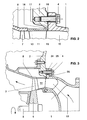
- FIG. 2 shows an enlarged section of FIG. 1, which roughly illustrates the size ratios of the gap widths.
- a sealing surface 17 to the gas inlet housing 1 is formed on the radially inner region of the gas outlet housing 2.
- a mounting gap 18 is arranged radially outside of this sealing surface 17 between the gas outlet housing 2 and the gas inlet housing 1.
- the inner ring 12 is supported on the gas inlet housing 1 in a rotationally secure manner by means of a plurality of positioning elements 19 designed as pins.
- the inner ring 12 For receiving the pins 19, the inner ring 12 has a corresponding number of thickenings 20 with first recesses 21 on its upstream side, while the gas inlet housing 1 has corresponding second recesses 22.
- Each of the first recesses 21 arranged in the thickenings 20 additionally has an inner gap 23 in the region of the pin 19 (FIG. 1).
- the nozzle ring 14 arranged directly in the flow channel 10 is exposed to the high exhaust gas temperatures during this process. Because its guide vanes 13 are relatively thin and the entire nozzle ring 14 also has a substantially smaller mass than the gas inlet housing 1, the gas outlet housing 2 or the cover ring 8, the nozzle ring 14 experiences a significantly greater temperature rise than the above-mentioned components surrounding it.
- the inventive design of the radial and the axial expansion gap 16, 15 allows the outer ring 11 of the nozzle ring 14 to expand freely in both the radial and the axial direction in accordance with the specific operating conditions.
- the substantially larger radial expansion of the material in the area between the outer ring 11 and the gas outlet housing 2 is compared to the possible axial expansion of the outer ring 11 and gas inlet housing 1 by the above. Ratio of the gap widths of about 4: 1 taken into account. In this way, the thermal stresses which form between the cover ring 8, the gas inlet housing 1, the gas outlet housing 2 and the nozzle ring 14 can be compensated.
- the nozzle ring 14 is on the one hand clamped diagonally between the cover ring 8 and the gas inlet housing 1 and on the other hand acts as a membrane between the components surrounding it. Due to the formation of the assembly gap 18, the sealing surface 17 is always in contact with the gas inlet housing 1. The sealing surface 17 prevents exhaust gas leakage to the environment. When using sheet metal as the material for the nozzle ring 14, its flexible design is additionally supported.
- the outer ring 11 is at full load of the diesel engine axially against the gas inlet housing 1 and radially against the gas outlet housing 2.
- the expansion gaps 15, 16 are closed during the operation of the exhaust gas turbine.
- no exhaust gas can penetrate into the cavity formed between the outer ring 11, the gas outlet housing 2 and the diffuser 8. In this way, both disturbances in the exhaust gas flow and gap losses are avoided, which results in higher efficiency.
- a clamping segment 24 which is axially form-fitting both with this and with the gas outlet housing 2 is arranged on the gas inlet housing 1 and is provided with recesses 25 designed as bores for the screws 4. Radial gaps 26 are formed between the clamping segment 24 and the gas inlet housing 1 (FIG. 3). As a result, the gas inlet housing 1 can also expand radially without increasing its operating voltages.
- the further arrangement and function of the components is analogous to the first embodiment.
Landscapes
- Engineering & Computer Science (AREA)
- General Engineering & Computer Science (AREA)
- Mechanical Engineering (AREA)
- Chemical & Material Sciences (AREA)
- Combustion & Propulsion (AREA)
- Chemical Kinetics & Catalysis (AREA)
- General Chemical & Material Sciences (AREA)
- Supercharger (AREA)
Abstract
Description
Die Erfindung betrifft die Abgasturbine eines mit einer Brennkraftmaschine verbundenen Abgasturboladers, gemäss dem Oberbegriff des Anspruchs 1.The invention relates to the exhaust gas turbine of an exhaust gas turbocharger connected to an internal combustion engine, according to the preamble of
Beim Betrieb eines Abgasturboladers ist dessen Abgasturbine von Seiten der mit ihr verbundenen Brennkraftmaschine relativ hohen Temperaturen ausgesetzt. Somit entstehen in den turbinenseitigen Bauteilen, wie z.B. dem Gaseintrittgehäuse, dem Düsenring, dem Abdeckring und dem Gasaustrittgehäuse grosse thermische Spannungen. Da jedes dieser Bauteile einen anderen Abstand zur Brennkraftmaschine besitzt und zudem unterschiedliche Materialien verwendet werden, differieren die Bauteiltemperaturen entsprechend. Die Folge sind unterschiedliche Wärmedehnungen mit Relativbewegungen zwischen den einzelnen Komponenten, welche zu Schraubenbrüchen, Gasleckagen und Bauteilrissen führen können. Deshalb spielt die Ausbildung und Anordnung der Trennstellen von Gaseintrittgehäuse, Gasaustrittgehäuse, Düsenring und Abdeckring eine wesentliche Rolle für die Funktionsfähigkeit eines Abgasturboladers.When an exhaust gas turbocharger is in operation, its exhaust gas turbine is exposed to relatively high temperatures on the part of the internal combustion engine connected to it. Thus, in the turbine-side components, e.g. the gas inlet housing, the nozzle ring, the cover ring and the gas outlet housing high thermal stresses. Since each of these components has a different distance from the internal combustion engine and different materials are also used, the component temperatures differ accordingly. The result is different thermal expansions with relative movements between the individual components, which can lead to screw breaks, gas leaks and component tears. Therefore, the design and arrangement of the separation points of the gas inlet housing, gas outlet housing, nozzle ring and cover ring play an essential role for the functionality of an exhaust gas turbocharger.
Aus der DE-A1-4223496 ist eine Verschraubung des Düsenrings mit dem Gaseintrittgehäuse bekannt. Dazu ist der Innenring des Düsenrings verdickt ausgebildet und mit einem zusätzlichen Flansch versehen, welcher die der Verbindung mit dem Gaseintrittgehäuse dienenden Schrauben aufnimmt.From DE-A1-4223496 a screw connection of the nozzle ring to the gas inlet housing is known. For this purpose, the inner ring of the nozzle ring is thickened and with an additional one Provide flange which receives the screws serving to connect the gas inlet housing.
Aufgrund der einseitigen Verschraubung kann es bei einer solchen Lösung zu irreversiblen Verwerfungen des Düsenrings kommen. Zudem besteht die Gefahr der Ausbildung einer Bypass-Strömung am Aussenring des Düsenrings, wodurch der Wirkungsgrad der Abgasturbine und damit der des Turboladers verringert wird. Wegen der grossen Wärmeentwicklung auf der Turbinenseite sitzen die zur Befestigung des Düsenrings dienenden Schrauben sehr fest und können nur sehr schwer gelöst werden. Damit wird die zum Auswechseln des Düsenrings erforderliche Montagezeit erheblich verlängert, was ein entscheidender Nachteil für die mit dem Abgasturbolader verbundene und in ihrer Leistung von diesem abhängige Brennkraftmaschine ist.Due to the one-sided screw connection, such a solution can lead to irreversible warping of the nozzle ring. There is also the risk of a bypass flow forming on the outer ring of the nozzle ring, as a result of which the efficiency of the exhaust gas turbine and thus that of the turbocharger is reduced. Because of the large amount of heat generated on the turbine side, the screws used to fasten the nozzle ring are very tight and can only be loosened with great difficulty. This considerably increases the assembly time required to replace the nozzle ring, which is a decisive disadvantage for the internal combustion engine which is connected to the exhaust gas turbocharger and whose performance depends on it.
Das EP-B1-191380 zeigt die Abgasturbine eines Abgasturboladers, deren Düsenring durch den Abdeckring gegen das Gaseintrittgehäuse verklemmt wird. Dazu besitzt der Aussenring des Düsenrings eine axiale Auskragung und der Abdeckring einen korrespondierenden Befestigungsflansch. Letzterer ist durch mehrere Schrauben mit dem Gaseintrittgehäuse verbunden. In Umfangsrichtung wird der Düsenring mittels formschlüssiger Zentrierbolzen am Gaseintrittgehäuse fixiert.EP-B1-191380 shows the exhaust gas turbine of an exhaust gas turbocharger, the nozzle ring of which is clamped against the gas inlet housing by the cover ring. For this purpose, the outer ring of the nozzle ring has an axial projection and the cover ring has a corresponding fastening flange. The latter is connected to the gas inlet housing by several screws. In the circumferential direction, the nozzle ring is fixed to the gas inlet housing by means of form-fitting centering bolts.
Beide Lösungen weisen den gemeinsamen Nachteil auf, dass der Düsenring jeweils ein zusätzliches Bauteil zur Anordnung bzw. Aufnahme von Befestigungselementen aufweist. Dadurch ist er aufwendig in der Herstellung und somit relativ teuer. Ausserdem sind sowohl die axiale Auskragung des Aussenrings als auch der Flansch des Innenrings aufgrund der bereits weiter oben beschriebenen thermischen Spannungen anrissgefährdet, wodurch eine sichere Befestigung des Düsenrings und damit die Funktionsfähigkeit des Turboladers nicht dauerhaft gewährleistet ist.Both solutions have the common disadvantage that the nozzle ring each has an additional component for arranging or receiving fastening elements. As a result, it is complex to manufacture and therefore relatively expensive. In addition, both the axial projection of the outer ring and the flange of the inner ring are at risk of cracking due to the thermal stresses already described above, as a result of which a secure attachment of the nozzle ring and thus the functionality of the turbocharger is not permanently guaranteed.
Die Erfindung versucht alle diese Nachteile zu vermeiden. Ihr liegt die Aufgabe zugrunde, die Abgasturbine eines Abgasturboladers so auszubilden, dass eine einfache und sichere Befestigung des Düsenrings gewährleistet ist.The invention tries to avoid all these disadvantages. It is based on the task of designing the exhaust gas turbine of an exhaust gas turbocharger in such a way that simple and secure attachment of the nozzle ring is ensured.
Erfindungsgemäss wird dies dadurch erreicht, dass bei einer Vorrichtung gemäss dem Oberbegriff des Anspruchs 1, der Düsenring mit seinem Aussenring am Abdeckring und mit seinem Innenring am Gaseintrittgehäuse anliegt. Zwischen dem Aussenring und dem Gaseintrittgehäuse ist ein axialer sowie zwischen dem Aussenring und dem Gasaustrittgehäuse ein radialer Dehnungsspalt ausgebildet.This is achieved according to the invention in that, in a device according to the preamble of
Die Vorteile der Erfindung liegen darin begründet, dass der Düsenring lediglich diagonal zwischen dem Gasaustrittgehäuse und dem Gaseintrittgehäuse verspannt ist. Aufgrund dieser Befestigung erfolgt der Kraftfluss im Düsenring ausgehend vom Abdeckring über den Aussenring, die Leitschaufeln und den Innenring, bis hin zum Gaseintrittgehäuse. Durch die beiden Dehnungsspalte kann sich der Düsenring sowohl in radiale als auch in axiale Richtung frei ausdehnen. Diese diagonale Verspannung des Düsenrings schafft die Voraussetzung für freie Wärmedehnungen zwischen den turbinenseitigen Bauteilen, so dass entweder keine thermischen Spannungen auftretenden oder diese ausgeglichen werden können.The advantages of the invention lie in the fact that the nozzle ring is only clamped diagonally between the gas outlet housing and the gas inlet housing. Due to this fastening, the flow of force in the nozzle ring takes place from the cover ring via the outer ring, the guide vanes and the inner ring to the gas inlet housing. The two expansion gaps allow the nozzle ring to expand freely in both the radial and axial directions. This diagonal bracing of the nozzle ring creates the conditions for free thermal expansion between the turbine-side components, so that either no thermal stresses occur or these can be compensated.
Anrissgefährdete, den Düsenring versteifende Bauteile sind nicht vorhanden. Er ist somit relativ weich, d.h. elastisch ausgebildet und wirkt gewissermassen als Membran zwischen den ihn umgebenden Bauteilen. Da der Düsenring keine Befestigungsflansche besitzt ist er einfach und preisgünstig zu fertigen. Weil demzufolge zu seiner Befestigung keine Schrauben erforderlich sind, wird auch bei Montage und Demontage Arbeitszeit gespart. Als zusätzlicher Vorteil kann der Düsenring nunmehr von beiden Seiten, d.h. sowohl verdichterseitig als auch von Seiten der Brennkraftmaschine montiert werden.There are no components at risk of cracking that stiffen the nozzle ring. It is thus relatively soft, that is to say elastic, and acts to a certain extent as a membrane between the components surrounding it. Since the nozzle ring has no mounting flanges, it is easy and inexpensive to manufacture. As a result, no screws are required to fix it, so there is also working time during assembly and disassembly saved. As an additional advantage, the nozzle ring can now be installed from both sides, ie both on the compressor side and on the internal combustion engine side.
Es ist besonders zweckmässig, wenn am Gasaustrittgehäuse eine Dichtfläche zum Gaseintrittgehäuse angeordnet ist. Radial ausserhalb der Dichtfläche ist zwischen dem Gasaustritt- sowie dem Gaseintrittgehäuse ein Montagespalt ausgebildet. Aufgrund dieser Ausbildung wird zwischen Gaseintritt- und Gasaustrittgehäuse eine gute Abdichtung erreicht.It is particularly expedient if a sealing surface to the gas inlet housing is arranged on the gas outlet housing. A mounting gap is formed radially outside the sealing surface between the gas outlet and gas inlet housings. Because of this design, a good seal is achieved between the gas inlet and outlet housing.
Ferner ist es vorteilhaft, wenn die Spaltweite des axialen bzw. des radialen Dehnungsspalts grösser/gleich der maximalen Wärmedehnung von Aussenring und Gaseintrittgehäuse bzw. von Aussenring und Gasaustrittgehäuse ausgebildet ist.It is also advantageous if the gap width of the axial or radial expansion gap is greater than / equal to the maximum thermal expansion of the outer ring and gas inlet housing or of the outer ring and gas outlet housing.
Auf diese Weise wird sichergestellt, dass der Düsenring bei allen Betriebszuständen der Abgasturbine seine elastische Form behält, d.h. keine Spannungen auftreten. Im Extremfall kann der Aussenring in axialer Richtung am Gaseintrittgehäuse und in radialer Richtung am Gasaustrittgehäuse leicht anliegen, ohne dass die entstehende Pressung zu einer Materialabnutzung führt. Dies hat den Vorteil, dass Gasleckagen verhindert werden können.This ensures that the nozzle ring retains its elastic shape in all operating states of the exhaust gas turbine, i.e. no tensions occur. In extreme cases, the outer ring can rest lightly in the axial direction on the gas inlet housing and in the radial direction on the gas outlet housing without the resulting pressure resulting in material wear. This has the advantage that gas leaks can be prevented.
Schliesslich weist sowohl der Aussen- als auch der Innenring jeweils eine deutlich geringere Materialdicke auf, als der Abdeckring bzw. das Gaseintrittgehäuse. Die sich daraus ergebenden minimalen Wanddickenunterschiede zwischen den Leitschaufeln des Düsenrings und seinem Aussen- bzw. Innenring haben nur geringe Wärmespannungen zur Folge.Finally, both the outer and the inner ring each have a significantly smaller material thickness than the cover ring or the gas inlet housing. The resulting minimal wall thickness differences between the guide vanes of the nozzle ring and its outer or inner ring only result in low thermal stresses.
Besonders vorteilhaft ist es, wenn Aussen- und Innenring aus Blech hergestellt sind. Damit kann der Düsenring sehr einfach und preisgünstig gefertigt werden.It is particularly advantageous if the outer and inner rings are made from sheet metal. This allows the nozzle ring to be manufactured very simply and inexpensively.
In einer zweiten Ausgestaltungsform der Erfindung ist am Gaseintrittgehäuse ein sowohl mit diesem als auch mit dem Gasaustrittgehäuse in axialer Richtung formschlüssiges Klemmsegment angeordnet und mit Ausnehmungen für die Verbindungselemente versehen. Zwischen dem Gaseintrittgehäuse und dem Klemmsegment ist zumindest ein radialer Spalt ausgebildet. Im Gegensatz zur ersten Ausgestaltungsform können auf diese Weise auch die Wärmedehnungen des Gaseintrittgehäuses kompensiert werden. Demzufolge wird die Verbindungsstelle von Gaseintritt- und Gasaustrittgehäuse entlastet, so dass deutlich niedrigere Betriebsspannungen auftreten. Aus diesem Grund ist die Lösung insbesondere auch für thermisch hochbelastete Turbolader geeignet.In a second embodiment of the invention, a clamping segment which is form-fitting both with the gas inlet housing and with the gas outlet housing in the axial direction is arranged on the gas inlet housing and is provided with recesses for the connecting elements. At least one radial gap is formed between the gas inlet housing and the clamping segment. In contrast to the first embodiment, the thermal expansions of the gas inlet housing can also be compensated for in this way. As a result, the connection point between the gas inlet and gas outlet housings is relieved, so that significantly lower operating voltages occur. For this reason, the solution is particularly suitable for turbochargers that are subject to high thermal loads.
In der Zeichnung sind zwei Ausführungsbeispiele der Erfindung anhand der Axialturbine eines Abgasturboladers dargestellt.In the drawing, two exemplary embodiments of the invention are shown on the basis of the axial turbine of an exhaust gas turbocharger.
Es zeigen:
- Fig. 1
- einen Teillängsschnitt des Abgasturboladers im Bereich der Abgasturbine;
- Fig. 2
- einen vergrösserten Ausschnitt von Fig. 1, im Bereich des Aussenrings;
- Fig. 3
- eine Darstellung entsprechend Fig. 1, jedoch in einem zweiten Ausführungsbeispiel.
- Fig. 1
- a partial longitudinal section of the exhaust gas turbocharger in the region of the exhaust gas turbine;
- Fig. 2
- an enlarged section of Figure 1, in the region of the outer ring.
- Fig. 3
- a representation corresponding to FIG. 1, but in a second embodiment.
Es sind nur die für das Verständnis der Erfindung wesentlichen Elemente gezeigt. Nicht dargestellt sind beispielsweise die Brennkraftmaschine und die Verdichterseite des Abgasturboladers. Die Strömungsrichtung des Arbeitsmittels ist mit Pfeilen bezeichnet.Only the elements essential for understanding the invention are shown. For example, the internal combustion engine and the compressor side of the exhaust gas turbocharger are not shown. The direction of flow of the working fluid is indicated by arrows.
Die Abgasturbine eines Turboladers weist ein von einem Gaseintritt- und einem Gasaustrittgehäuse 1, 2 gebildetes Turbinengehäuse 3 auf, welches mittels als Schrauben ausgebildeter Verbindungselemente 4 zusammengehalten wird. Im Turbinengehäuse 3 ist ein von einer Welle 5 getragenes Turbinenlaufrad 6 mit Laufschaufeln 7 angeordnet. Das Turbinenlaufrad 6 wird nach aussen von einem als Diffusor ausgebildeten Abdeckring 8 begrenzt, welcher seinerseits durch Schrauben 9 am Gasaustrittgehäuse 2 befestigt ist. Zwischen dem Turbinenlaufrad 6 und dem Turbinengehäuse 3 ist ein Strömungskanal 10 ausgebildet, welcher die Abgase eines nicht dargestellten, mit dem Turbolader verbundenen Dieselmotors aufnimmt und zum Turbinenlaufrad 6 weiterleitet. Natürlich kann auch eine andere Brennkraftmaschine mit dem Turbolader verbunden sein.The exhaust gas turbine of a turbocharger has a
Stromauf des Turbinenlaufrades 6 ist im Strömungskanal 10 ein aus einem Aussenring 11, einem Innenring 12 sowie einer Anzahl dazwischen ausgebildeter Leitschaufeln 13 bestehender und als Gussteil ausgebildeter Düsenring 14 angeordnet. Letzterer ist axial zwischen dem Abdeckring 8 und dem Gaseintrittgehäuse 1 verspannt sowie radial innerhalb des Gasaustrittgehäuses 2 angeordnet. Dazu liegt der Düsenring 14 mit seinem Aussenring 11 am Abdeckring 8 und mit seinem Innenring 12 am Gaseintrittgehäuse 1 an. Sowohl sein Aussen- als auch der Innenring 11, 12 weisen jeweils eine deutlich geringere Materialdicke als der Abdeckring 8 bzw. das Gaseintrittgehäuse 1 auf (Fig. 1). Natürlich kann der Düsenring 14 auch aus anderen Materialien, wie beispielsweise aus Blech- oder Stahlprofilen gefertigt werden oder aus Keramik bestehen.Arranged upstream of the
Zwischen dem Aussenring 11 und dem Gaseintrittgehäuse 1 ist ein axialer Dehnungsspalt 15 sowie zwischen dem Aussenring 11 und dem Gasaustrittgehäuse 2 ein radialer Dehnungsspalt 16 ausgebildet. Die Spaltweite der Dehnungsspalte 15, 16 ist grösser als die maximale Wärmedehnung von Aussenring 11 und Gaseintrittgehäuse 1 bzw. von Aussenring 11 und Gasaustrittgehäuse 2. Dabei beträgt das Verhältnis der Spaltweite des radialen Dehnungsspaltes 16 zur Spaltweite des axialen Dehnungsspaltes 15 etwa 4:1. Dieses Verhältnis ergibt sich aus den radialen und den axialen Abmessungen des Düsenrings 14. Natürlich können die Spaltweiten auch der maximalen Wärmedehnung der beteiligten Bauteile entsprechen.An
In Fig. 2 ist ein vergrösserter Ausschnitt von Fig. 1 dargestellt, welcher die Grössenverhältnisse der Spaltweiten in etwa verdeutlicht. Am radial inneren Bereich des Gasaustrittgehäuses 2 ist eine Dichtfläche 17 zum Gaseintrittgehäuse 1 ausgebildet. Radial ausserhalb dieser Dichtfläche 17 ist zwischen dem Gasaustrittgehäuse 2 sowie dem Gaseintrittgehäuse 1 ein Montagespalt 18 angeordnet.FIG. 2 shows an enlarged section of FIG. 1, which roughly illustrates the size ratios of the gap widths. A sealing
Der Innenring 12 ist mittels mehreren als Stifte ausgebildeten Positionierlementen 19 verdrehsicher am Gaseintrittgehäuse 1 abgestützt. Zur Aufnahme der Stifte 19 besitzt der Innenring 12 an seiner stromaufwärtigen Seite eine entsprechende Anzahl von Verdickungen 20 mit ersten Ausnehmungen 21, während das Gaseintrittgehäuse 1 damit korrespondierende, zweite Ausnehmungen 22 aufweist. Jede der in den Verdickungen 20 angeordneten ersten Ausnehmungen 21 weist im Bereich des Stiftes 19 zusätzlich einen inneren Spalt 23 auf (Fig. 1).The
Beim Betrieb des Dieselmotors gelangen dessen heisse Abgase über das Gaseintrittgehäuse 1 bzw. den darin angeordneten Strömungskanal 10 zum Turbinenlaufrad 6 der Abgasturbine. Dabei hat der Düsenring 14 die Aufgabe, die Abgase optimal auf die Laufschaufeln 7 des Turbinenlaufrades 6 zu leiten. Das somit angetriebene Turbinenlaufrad 6 sorgt seinerseits für den Antrieb des mit ihm verbundenen, nicht dargestellten Verdichters. Die im Verdichter komprimierte Luft wird zur Aufladung, d.h. zur Leistungssteigerung des Dieselmotors eingesetzt.When the diesel engine is operating, its hot exhaust gases pass through the
Der direkt im Strömungskanal 10 angeordnete Düsenring 14 ist bei diesem Vorgang den hohen Abgastemperaturen ausgesetzt. Weil seine Leitschaufeln 13 relativ dünn sind und der gesamte Düsenring 14 zudem eine wesentlich geringere Masse als das Gaseintrittgehäuse 1, das Gasaustrittgehäuse 2 bzw. der Abdeckring 8 besitzt, erfährt der Düsenring 14 einen deutlich grösseren Temperaturanstieg als die genannten, ihn umgebenden Bauteile.The
Durch die erfindungsgemässe Ausbildung des radialen und des axialen Dehnungsspaltes 16, 15 kann sich der Aussenring 11 des Düsenrings 14 entsprechend den konkreten Betriebsbedingungen sowohl in radialer als auch in axialer Richtung frei ausdehnen. Dabei wird der wesentlich grösseren radialen Ausdehnung des Materials im Bereich zwischen dem Aussenring 11 und dem Gasaustrittgehäuse 2, gegenüber der möglichen axialen Ausdehnung von Aussenring 11 und Gaseintrittgehäuse 1 durch das o.g. Verhältnis der Spaltweiten von etwa 4:1 Rechnung getragen. Auf diese Weise können die sich zwischen dem Abdeckring 8, dem Gaseintrittgehäuse 1, dem Gasaustrittgehäuse 2 sowie dem Düsenring 14 ausbildenden thermischen Spannungen ausgeglichen werden. Der Düsenring 14 ist so zum einen diagonal zwischen dem Abdeckring 8 und dem Gaseintrittgehäuse 1 verspannt und wirkt zum anderen als Membran zwischen den ihn umgebenden Bauteilen. Durch die Ausbildung des Montagespalts 18 liegt die Dichtfläche 17 stets am Gaseintrittgehäuse 1 an. Die Dichtfläche 17 verhindert eine Abgasleckage an die Umgebung. Bei Verwendung von Blech als Material für den Düsenring 14 wird dessen flexible Ausbildung zusätzlich unterstützt.The inventive design of the radial and the
Entspricht die Spaltweite des axialen und die des radialen Dehnungsspaltes 15, 16 der maximalen Wärmedehnung von Aussenring 11 und Gaseintrittgehäuse 1 bzw. von Aussenring 11 und Gasaustrittgehäuse 2, so liegt der Aussenring 11 bei Vollast des Dieselmotors axial am Gaseintrittgehäuse 1 und radial am Gasaustrittgehäuse 2 an. Dadurch werden die Dehnungsspalte 15, 16 während dem Betrieb der Abgasturbine verschlossen. Somit kann kein Abgas in den zwischen dem Aussenring 11, dem Gasaustrittgehäuse 2 und dem Diffusor 8 ausgebildeten Hohlraum eindringen. Auf diese Weise werden sowohl Störungen der Abgasströmung als auch Spaltverluste vermieden, was einen höheren Wirkungsgrad zur Folge hat.Corresponds to the gap width of the axial and that of the
In einem zweiten Ausführungsbeispiel ist am Gaseintrittgehäuse 1 ein sowohl mit diesem als auch mit dem Gasaustrittgehäuse 2 axial formschlüssiges Klemmsegment 24 angeordnet und mit als Bohrungen ausgebildeten Ausnehmungen 25 für die Schrauben 4 versehen. Zwischen dem Klemmsegment 24 und dem Gaseintrittgehäuse 1 sind radiale Spalte 26 ausgebildet (Fig. 3). Dadurch kann sich auch das Gaseintrittgehäuse 1 ohne Erhöhung seiner Betriebsspannungen radial ausdehnen. Die weitere Anordnung und Funktion der Bauteile ist analog dem ersten Ausführungsbeispiel.In a second exemplary embodiment, a clamping
- 11
- GaseintrittgehäuseGas inlet casing
- 22nd
- GasaustrittgehäuseGas outlet housing
- 33rd
- TurbinenghäuseTurbine casing
- 44th
- Verbindungselement, SchraubeFastener, screw
- 55
- Wellewave
- 66
- TurbinenlaufradTurbine impeller
- 77
- LaufschaufelBlade
- 88th
- Abdeckring, DiffusorCover ring, diffuser
- 99
- Schraubescrew
- 1010th
- StrömungskanalFlow channel
- 1111
- AussenringOuter ring
- 1212th
- InnenringInner ring
- 1313
- Leitschaufelvane
- 1414
- DüsenringNozzle ring
- 1515
- axialer Dehnungsspaltaxial expansion gap
- 1616
- radialer Dehnungsspaltradial expansion gap
- 1717th
- DichtflächeSealing surface
- 1818th
- MontagespaltAssembly gap
- 1919th
- Positionierlement, StiftPositioning element, pen
- 2020th
- Verdickung, von 12Thickening, from 12
- 2121
- Ausnehmung, ersteRecess, first
- 2222
- Ausnehmung, zweiteRecess, second
- 2323
- Spalt, innenGap, inside
- 2424th
- KlemmsegmentClamping segment
- 2525th
- Ausnehmung, BohrungRecess, bore
- 2626
- Spalt, radialGap, radial
Claims (7)
Applications Claiming Priority (2)
| Application Number | Priority Date | Filing Date | Title |
|---|---|---|---|
| DE19618314 | 1996-05-08 | ||
| DE19618314A DE19618314A1 (en) | 1996-05-08 | 1996-05-08 | Exhaust gas turbine of an exhaust gas turbocharger |
Publications (2)
| Publication Number | Publication Date |
|---|---|
| EP0806548A1 true EP0806548A1 (en) | 1997-11-12 |
| EP0806548B1 EP0806548B1 (en) | 2000-03-01 |
Family
ID=7793599
Family Applications (1)
| Application Number | Title | Priority Date | Filing Date |
|---|---|---|---|
| EP97810216A Expired - Lifetime EP0806548B1 (en) | 1996-05-08 | 1997-04-11 | Turbine of an exhaust turbocharger |
Country Status (8)
| Country | Link |
|---|---|
| US (1) | US5868553A (en) |
| EP (1) | EP0806548B1 (en) |
| JP (1) | JP4082756B2 (en) |
| KR (1) | KR100476516B1 (en) |
| CN (1) | CN1105231C (en) |
| CZ (1) | CZ290760B6 (en) |
| DE (2) | DE19618314A1 (en) |
| PL (1) | PL319809A1 (en) |
Cited By (3)
| Publication number | Priority date | Publication date | Assignee | Title |
|---|---|---|---|---|
| EP0999349A2 (en) | 1998-11-04 | 2000-05-10 | Asea Brown Boveri AG | Axial turbine |
| US7086233B2 (en) | 2003-11-26 | 2006-08-08 | Siemens Power Generation, Inc. | Blade tip clearance control |
| US7708518B2 (en) | 2005-06-23 | 2010-05-04 | Siemens Energy, Inc. | Turbine blade tip clearance control |
Families Citing this family (24)
| Publication number | Priority date | Publication date | Assignee | Title |
|---|---|---|---|---|
| KR100293492B1 (en) * | 1998-12-24 | 2001-07-12 | 이계철 | Digital signature verification method using denial protocol |
| DE19925684A1 (en) * | 1999-06-04 | 2000-12-07 | Asea Brown Boveri | Fastener for turbocharger to base e.g. IC engine has positively interconnecting connection elements on bearing housing and main fastener foot |
| US6302647B1 (en) * | 2000-05-10 | 2001-10-16 | General Motors Corporation | Turbine inlet scroll |
| US6287091B1 (en) * | 2000-05-10 | 2001-09-11 | General Motors Corporation | Turbocharger with nozzle ring coupling |
| US6364606B1 (en) | 2000-11-08 | 2002-04-02 | Allison Advanced Development Company | High temperature capable flange |
| AU2002328105A1 (en) * | 2002-09-05 | 2004-03-29 | Honeywell International Inc. | Turbocharger comprising a variable nozzle device |
| GB2401652B (en) * | 2003-05-14 | 2006-05-03 | Malcolm George Leavesley | Turbocharger apparatus having an exhaust gas recirculating system for preventing gas leakage from the turbocharger apparatus |
| EP2176521B1 (en) * | 2007-07-27 | 2015-11-04 | Ansaldo Energia S.p.A. | Steam turbine stage |
| EP2080871A1 (en) * | 2008-01-15 | 2009-07-22 | ABB Turbo Systems AG | Variable guide vane mechanism |
| CN102348868B (en) * | 2009-01-20 | 2014-11-05 | 威廉国际有限责任公司 | Turbocharger core and turbine nozzle cartridge assembly |
| US20120023936A1 (en) * | 2010-07-30 | 2012-02-02 | Caterpillar Inc. | Nozzled turbocharger turbine |
| US8591184B2 (en) * | 2010-08-20 | 2013-11-26 | General Electric Company | Hub flowpath contour |
| DE102011080596A1 (en) * | 2011-08-08 | 2013-02-14 | Abb Turbo Systems Ag | Arrangement for conducting an exhaust gas in an exhaust gas flowed axially |
| JP6033154B2 (en) * | 2013-03-29 | 2016-11-30 | 三菱重工業株式会社 | Axial-flow rotating machine and diffuser |
| JP5889266B2 (en) * | 2013-11-14 | 2016-03-22 | 三菱重工業株式会社 | Turbine |
| US10066639B2 (en) | 2015-03-09 | 2018-09-04 | Caterpillar Inc. | Compressor assembly having a vaneless space |
| US10006341B2 (en) | 2015-03-09 | 2018-06-26 | Caterpillar Inc. | Compressor assembly having a diffuser ring with tabs |
| CN109098780B (en) * | 2018-05-24 | 2024-05-14 | 中车大连机车研究所有限公司 | Gas exhaust casing of turbocharger |
| DE102019101602A1 (en) * | 2019-01-23 | 2020-07-23 | Man Energy Solutions Se | Fluid machine |
| US11371704B2 (en) | 2019-04-05 | 2022-06-28 | Raytheon Technologies Corporation | Pre-diffuser for a gas turbine engine |
| US11384936B2 (en) | 2019-04-05 | 2022-07-12 | Raytheon Technologies Corporation | Pre-diffuser for a gas turbine engine |
| US11136995B2 (en) * | 2019-04-05 | 2021-10-05 | Raytheon Technologies Corporation | Pre-diffuser for a gas turbine engine |
| CN115387906B (en) * | 2022-05-12 | 2024-04-16 | 中国航发四川燃气涡轮研究院 | Air inlet bearing frame connecting structure of low inlet hub ratio engine and assembling method |
| US12529322B1 (en) | 2024-11-08 | 2026-01-20 | Pratt & Whitney Canada Corp. | Gas turbine engine stator vane stage |
Citations (4)
| Publication number | Priority date | Publication date | Assignee | Title |
|---|---|---|---|---|
| DE928746C (en) * | 1952-12-04 | 1955-06-10 | Maschf Augsburg Nuernberg Ag | Diffuser for exhaust gas fan |
| US4477086A (en) * | 1982-11-01 | 1984-10-16 | United Technologies Corporation | Seal ring with slidable inner element bridging circumferential gap |
| US5395211A (en) * | 1994-01-14 | 1995-03-07 | United Technologies Corporation | Stator structure for a rotary machine |
| US5423659A (en) * | 1994-04-28 | 1995-06-13 | United Technologies Corporation | Shroud segment having a cut-back retaining hook |
Family Cites Families (10)
| Publication number | Priority date | Publication date | Assignee | Title |
|---|---|---|---|---|
| DE1036581B (en) * | 1956-09-22 | 1958-08-14 | Maschf Augsburg Nuernberg Ag | Attachment of the nozzle ring of exhaust gas turbines |
| JPS58564B2 (en) * | 1976-08-03 | 1983-01-07 | 三菱重工業株式会社 | exhaust turbine supercharger |
| GB2037901B (en) * | 1978-11-25 | 1982-07-28 | Rolls Royce | Nozzle guide vane assembly |
| EP0103260A3 (en) * | 1982-09-06 | 1984-09-26 | Hitachi, Ltd. | Clearance control for turbine blade tips |
| EP0118051B1 (en) * | 1983-03-04 | 1988-02-03 | BBC Brown Boveri AG | Connection between the hot and cold parts of an uncooled turbo charger |
| SU1480776A3 (en) * | 1985-02-20 | 1989-05-15 | Ббц Аг Браун, Бовери Унд Ко. (Фирма) | I.c. engine turbocharger |
| JPS62135802U (en) * | 1986-02-21 | 1987-08-26 | ||
| US5207565A (en) * | 1992-02-18 | 1993-05-04 | Alliedsignal Inc. | Variable geometry turbocharger with high temperature insert in turbine throat |
| US5271714A (en) * | 1992-07-09 | 1993-12-21 | General Electric Company | Turbine nozzle support arrangement |
| DE4223496A1 (en) * | 1992-07-17 | 1994-01-20 | Asea Brown Boveri | Reducing kinetic energy of bursting parts in turbines - involves crumple zone between inner and outer rings set between housing and rotor to absorb energy and contain fractured parts |
-
1996
- 1996-05-08 DE DE19618314A patent/DE19618314A1/en not_active Withdrawn
-
1997
- 1997-04-11 EP EP97810216A patent/EP0806548B1/en not_active Expired - Lifetime
- 1997-04-11 DE DE59701158T patent/DE59701158D1/en not_active Expired - Lifetime
- 1997-04-15 US US08/839,644 patent/US5868553A/en not_active Expired - Lifetime
- 1997-05-05 PL PL97319809A patent/PL319809A1/en unknown
- 1997-05-06 CZ CZ19971376A patent/CZ290760B6/en not_active IP Right Cessation
- 1997-05-07 JP JP11681797A patent/JP4082756B2/en not_active Expired - Lifetime
- 1997-05-07 KR KR1019970017523A patent/KR100476516B1/en not_active Expired - Lifetime
- 1997-05-08 CN CN97110900A patent/CN1105231C/en not_active Expired - Lifetime
Patent Citations (4)
| Publication number | Priority date | Publication date | Assignee | Title |
|---|---|---|---|---|
| DE928746C (en) * | 1952-12-04 | 1955-06-10 | Maschf Augsburg Nuernberg Ag | Diffuser for exhaust gas fan |
| US4477086A (en) * | 1982-11-01 | 1984-10-16 | United Technologies Corporation | Seal ring with slidable inner element bridging circumferential gap |
| US5395211A (en) * | 1994-01-14 | 1995-03-07 | United Technologies Corporation | Stator structure for a rotary machine |
| US5423659A (en) * | 1994-04-28 | 1995-06-13 | United Technologies Corporation | Shroud segment having a cut-back retaining hook |
Cited By (4)
| Publication number | Priority date | Publication date | Assignee | Title |
|---|---|---|---|---|
| EP0999349A2 (en) | 1998-11-04 | 2000-05-10 | Asea Brown Boveri AG | Axial turbine |
| US6318961B1 (en) | 1998-11-04 | 2001-11-20 | Asea Brown Boveri Ag | Axial turbine |
| US7086233B2 (en) | 2003-11-26 | 2006-08-08 | Siemens Power Generation, Inc. | Blade tip clearance control |
| US7708518B2 (en) | 2005-06-23 | 2010-05-04 | Siemens Energy, Inc. | Turbine blade tip clearance control |
Also Published As
| Publication number | Publication date |
|---|---|
| CN1105231C (en) | 2003-04-09 |
| EP0806548B1 (en) | 2000-03-01 |
| PL319809A1 (en) | 1997-11-10 |
| DE19618314A1 (en) | 1997-11-13 |
| US5868553A (en) | 1999-02-09 |
| JPH1047012A (en) | 1998-02-17 |
| DE59701158D1 (en) | 2000-04-06 |
| CZ137697A3 (en) | 1997-11-12 |
| CN1172893A (en) | 1998-02-11 |
| CZ290760B6 (en) | 2002-10-16 |
| KR970075266A (en) | 1997-12-10 |
| JP4082756B2 (en) | 2008-04-30 |
| KR100476516B1 (en) | 2005-06-16 |
Similar Documents
| Publication | Publication Date | Title |
|---|---|---|
| EP0806548B1 (en) | Turbine of an exhaust turbocharger | |
| EP1664489B1 (en) | Gas turbine comprising a ring-shaped sealing means | |
| DE19703033A1 (en) | Exhaust gas turbine of a turbocharger | |
| DE69309794T2 (en) | Nozzle holder for turbines | |
| DE69926332T2 (en) | Brush seal for a turbo machine | |
| DE69321776T2 (en) | Gas turbine | |
| DE69932966T2 (en) | Guide vane assembly for a turbomachine | |
| DE10210866C1 (en) | Guide blade segment fixing device for flow channel of aircraft gas turbine uses slot and hook fixing and pin fitting through latter | |
| EP1736635B1 (en) | Air transfer system between compressor and turbine of a gas turbine engine | |
| EP3548705B1 (en) | Turbocharger | |
| DE102015219556A1 (en) | Diffuser for radial compressor, centrifugal compressor and turbo machine with centrifugal compressor | |
| EP0999349B1 (en) | Axial turbine | |
| EP0806547B1 (en) | Axial turbine for turbochargers | |
| DE102007050916A1 (en) | Stator arrangement for compressor of fluid conveying arrangement in gas turbine engine, has radial passage conduit formed in part of stator ring segment, where radial passage conduit is arranged adjacent to stator blade passage conduit | |
| EP0984137A2 (en) | Method and device to balance axial thrust in a turbocharger | |
| EP3392463B1 (en) | Flow engine | |
| DE102010036071A1 (en) | Housing-side structure of a turbomachine | |
| EP1673519B1 (en) | Sealing arrangement for a gas turbine | |
| EP3737850B1 (en) | Filter muffler for an exhaust gas turbocharger of an internal combustion engine | |
| EP4496938B1 (en) | Nozzle ring for a radial turbine, exhaust gas turbine and exhaust gas turbocharger | |
| DE102023118123B4 (en) | Turbine and turbocharger with a turbine | |
| DE3309812C2 (en) | Outer housing for a gas turbine engine | |
| DE4100225C2 (en) | ||
| DE102021121533A1 (en) | Exhaust gas turbocharger with adjustable diffuser | |
| EP4607002A1 (en) | Flow machine with a flow channel |
Legal Events
| Date | Code | Title | Description |
|---|---|---|---|
| PUAI | Public reference made under article 153(3) epc to a published international application that has entered the european phase |
Free format text: ORIGINAL CODE: 0009012 |
|
| AK | Designated contracting states |
Kind code of ref document: A1 Designated state(s): DE FR GB |
|
| 17P | Request for examination filed |
Effective date: 19980420 |
|
| GRAG | Despatch of communication of intention to grant |
Free format text: ORIGINAL CODE: EPIDOS AGRA |
|
| GRAG | Despatch of communication of intention to grant |
Free format text: ORIGINAL CODE: EPIDOS AGRA |
|
| GRAH | Despatch of communication of intention to grant a patent |
Free format text: ORIGINAL CODE: EPIDOS IGRA |
|
| 17Q | First examination report despatched |
Effective date: 19990624 |
|
| GRAH | Despatch of communication of intention to grant a patent |
Free format text: ORIGINAL CODE: EPIDOS IGRA |
|
| GRAA | (expected) grant |
Free format text: ORIGINAL CODE: 0009210 |
|
| AK | Designated contracting states |
Kind code of ref document: B1 Designated state(s): DE FR GB |
|
| REF | Corresponds to: |
Ref document number: 59701158 Country of ref document: DE Date of ref document: 20000406 |
|
| GBT | Gb: translation of ep patent filed (gb section 77(6)(a)/1977) |
Effective date: 20000518 |
|
| ET | Fr: translation filed | ||
| PLBE | No opposition filed within time limit |
Free format text: ORIGINAL CODE: 0009261 |
|
| STAA | Information on the status of an ep patent application or granted ep patent |
Free format text: STATUS: NO OPPOSITION FILED WITHIN TIME LIMIT |
|
| 26N | No opposition filed | ||
| REG | Reference to a national code |
Ref country code: GB Ref legal event code: IF02 |
|
| REG | Reference to a national code |
Ref country code: FR Ref legal event code: CD Ref country code: FR Ref legal event code: CA |
|
| REG | Reference to a national code |
Ref country code: GB Ref legal event code: 732E |
|
| REG | Reference to a national code |
Ref country code: FR Ref legal event code: TP |
|
| REG | Reference to a national code |
Ref country code: FR Ref legal event code: PLFP Year of fee payment: 20 |
|
| PGFP | Annual fee paid to national office [announced via postgrant information from national office to epo] |
Ref country code: DE Payment date: 20160421 Year of fee payment: 20 Ref country code: GB Payment date: 20160421 Year of fee payment: 20 |
|
| PGFP | Annual fee paid to national office [announced via postgrant information from national office to epo] |
Ref country code: FR Payment date: 20160421 Year of fee payment: 20 |
|
| REG | Reference to a national code |
Ref country code: DE Ref legal event code: R071 Ref document number: 59701158 Country of ref document: DE |
|
| REG | Reference to a national code |
Ref country code: GB Ref legal event code: PE20 Expiry date: 20170410 |
|
| PG25 | Lapsed in a contracting state [announced via postgrant information from national office to epo] |
Ref country code: GB Free format text: LAPSE BECAUSE OF EXPIRATION OF PROTECTION Effective date: 20170410 |