EP1129232B1 - Apparatus for coating objects through pvd - Google Patents
Apparatus for coating objects through pvd Download PDFInfo
- Publication number
- EP1129232B1 EP1129232B1 EP99971870A EP99971870A EP1129232B1 EP 1129232 B1 EP1129232 B1 EP 1129232B1 EP 99971870 A EP99971870 A EP 99971870A EP 99971870 A EP99971870 A EP 99971870A EP 1129232 B1 EP1129232 B1 EP 1129232B1
- Authority
- EP
- European Patent Office
- Prior art keywords
- objects
- pvd
- carriers
- preprocessing
- postprocessing
- Prior art date
- Legal status (The legal status is an assumption and is not a legal conclusion. Google has not performed a legal analysis and makes no representation as to the accuracy of the status listed.)
- Expired - Lifetime
Links
Images


Classifications
-
- C—CHEMISTRY; METALLURGY
- C23—COATING METALLIC MATERIAL; COATING MATERIAL WITH METALLIC MATERIAL; CHEMICAL SURFACE TREATMENT; DIFFUSION TREATMENT OF METALLIC MATERIAL; COATING BY VACUUM EVAPORATION, BY SPUTTERING, BY ION IMPLANTATION OR BY CHEMICAL VAPOUR DEPOSITION, IN GENERAL; INHIBITING CORROSION OF METALLIC MATERIAL OR INCRUSTATION IN GENERAL
- C23C—COATING METALLIC MATERIAL; COATING MATERIAL WITH METALLIC MATERIAL; SURFACE TREATMENT OF METALLIC MATERIAL BY DIFFUSION INTO THE SURFACE, BY CHEMICAL CONVERSION OR SUBSTITUTION; COATING BY VACUUM EVAPORATION, BY SPUTTERING, BY ION IMPLANTATION OR BY CHEMICAL VAPOUR DEPOSITION, IN GENERAL
- C23C14/00—Coating by vacuum evaporation, by sputtering or by ion implantation of the coating forming material
- C23C14/22—Coating by vacuum evaporation, by sputtering or by ion implantation of the coating forming material characterised by the process of coating
- C23C14/56—Apparatus specially adapted for continuous coating; Arrangements for maintaining the vacuum, e.g. vacuum locks
-
- B—PERFORMING OPERATIONS; TRANSPORTING
- B05—SPRAYING OR ATOMISING IN GENERAL; APPLYING FLUENT MATERIALS TO SURFACES, IN GENERAL
- B05D—PROCESSES FOR APPLYING FLUENT MATERIALS TO SURFACES, IN GENERAL
- B05D5/00—Processes for applying liquids or other fluent materials to surfaces to obtain special surface effects, finishes or structures
- B05D5/06—Processes for applying liquids or other fluent materials to surfaces to obtain special surface effects, finishes or structures to obtain multicolour or other optical effects
- B05D5/067—Metallic effect
-
- C—CHEMISTRY; METALLURGY
- C23—COATING METALLIC MATERIAL; COATING MATERIAL WITH METALLIC MATERIAL; CHEMICAL SURFACE TREATMENT; DIFFUSION TREATMENT OF METALLIC MATERIAL; COATING BY VACUUM EVAPORATION, BY SPUTTERING, BY ION IMPLANTATION OR BY CHEMICAL VAPOUR DEPOSITION, IN GENERAL; INHIBITING CORROSION OF METALLIC MATERIAL OR INCRUSTATION IN GENERAL
- C23C—COATING METALLIC MATERIAL; COATING MATERIAL WITH METALLIC MATERIAL; SURFACE TREATMENT OF METALLIC MATERIAL BY DIFFUSION INTO THE SURFACE, BY CHEMICAL CONVERSION OR SUBSTITUTION; COATING BY VACUUM EVAPORATION, BY SPUTTERING, BY ION IMPLANTATION OR BY CHEMICAL VAPOUR DEPOSITION, IN GENERAL
- C23C14/00—Coating by vacuum evaporation, by sputtering or by ion implantation of the coating forming material
- C23C14/22—Coating by vacuum evaporation, by sputtering or by ion implantation of the coating forming material characterised by the process of coating
- C23C14/50—Substrate holders
- C23C14/505—Substrate holders for rotation of the substrates
-
- C—CHEMISTRY; METALLURGY
- C23—COATING METALLIC MATERIAL; COATING MATERIAL WITH METALLIC MATERIAL; CHEMICAL SURFACE TREATMENT; DIFFUSION TREATMENT OF METALLIC MATERIAL; COATING BY VACUUM EVAPORATION, BY SPUTTERING, BY ION IMPLANTATION OR BY CHEMICAL VAPOUR DEPOSITION, IN GENERAL; INHIBITING CORROSION OF METALLIC MATERIAL OR INCRUSTATION IN GENERAL
- C23C—COATING METALLIC MATERIAL; COATING MATERIAL WITH METALLIC MATERIAL; SURFACE TREATMENT OF METALLIC MATERIAL BY DIFFUSION INTO THE SURFACE, BY CHEMICAL CONVERSION OR SUBSTITUTION; COATING BY VACUUM EVAPORATION, BY SPUTTERING, BY ION IMPLANTATION OR BY CHEMICAL VAPOUR DEPOSITION, IN GENERAL
- C23C14/00—Coating by vacuum evaporation, by sputtering or by ion implantation of the coating forming material
- C23C14/22—Coating by vacuum evaporation, by sputtering or by ion implantation of the coating forming material characterised by the process of coating
- C23C14/56—Apparatus specially adapted for continuous coating; Arrangements for maintaining the vacuum, e.g. vacuum locks
- C23C14/568—Transferring the substrates through a series of coating stations
Definitions
- the present invention relates to an apparatus for coating objects by means of PVD (Physical Vapour Deposition), comprising:
- Such apparatus are generally known. They are for instance used to apply a thin layer of metal on plastics to give the object the appearance of metal. Examples hereof are for instance caps for cosmetics bottles, prizes such as presented at sporting events, car components and the like.
- the objects for processing are placed on racks and provided with a lacquer coating.
- This lacquer coating enhances adhesion between the plastic from which the object is made and the metal coating to be applied thereto.
- the lacquer coating moreover provides a smooth surface, so that the reflection of the metal to be coated thereon is improved.
- the pretreatment can also comprise a treatment prior to lacquering, such as a flame treatment.
- a treatment prior to lacquering such as a flame treatment.
- the surface properties of the plastic object are hereby changed so that the lacquer adheres better to the plastic.
- the objects for processing are subsequently placed in a vacuum vessel.
- PVD Physical Vapour Deposition
- the objects are thereafter subjected to a posttreatment, which is generally formed by a new lacquer treatment. It is pointed out here that the applied metal layer is extremely thin and is easily damaged. In order to protect this layer a protective lacquer coating is therefore applied. This lacquer coating further provides the option of changing the colour. In general use is made of aluminium as PVD material, wherein it is possible by colouring the lacquer to change the colour to for instance gold or copper colour.
- a problem with this method generally used heretofore is that many operations must inevitably be performed manually, requiring much human labour. This is caused by the discontinuous character of the PVD process and by the relatively long drying time of the lacquers once they have been applied to the plastic objects. The work is moreover usually difficult.
- WO-A-97/28290 discloses an apparatus for applying at least one coating to objects by means of vapour deposition (PVD) under vacuum, comprising:
- This prior art apparatus is adapted to procedure cathode ray tubes, involving the sputtering of metal coatings on glass.
- the aim of the invention is to provide an apparatus which is adapted to apply a metal coat on materials, which can only be coated if they have been covered by a coat of lacquer .
- the apparatus comprises:
- the semi-continuous character of the PVD device enables successive treatment of the carriers with a series of objects. Because the transport device is adapted for this purpose, and moreover extends through the preprocessing device and postprocessing device, it becomes possible to treat the objects for vapour deposition without loading and unloading operations. This combination of measures thus enables the use of a certain degree of automation; only at the start do the objects have to be placed on the carriers, and after completion of the postprocessing they can be removed therefrom. Handling of the objects between the treatments, albeit placed on racks, is dispensed with.
- the carriers are elongate and the transport device is adapted to move the carriers substantially in the longitudinal direction.
- the transport device has a closed configuration and extends in two directions through the PVD device.
- buffers between the preprocessing device and the PVD device, and between the PVD device and the postprocessing device have the function of compensating for the semi-continuity of the process performed in the PVD devices.
- the buffers are adapted to move the carriers in transverse direction, the buffers take up less space.
- the preprocessing device comprises a blower device for blowing dust from the objects for treating.
- This blower device is preferably adapted to blow ionized air.
- the carriers are provided with interchangeable object holders.
- This measure provides the advantage that the carriers can be used for different types of object; only the object holders have to be exchanged. This is particularly important in respect of the cost of the carriers; these carriers after all comprise expensive components manufactured with great precision.
- the toothed wheels are preferably arranged under the top side of the carrier. This provides the option of arranging protective means, so that lacquer dripping from the objects cannot reach the toothed wheels.
- the toothed wheels are let into openings arranged in the carrier and the toothed wheels protrude outside the side walls of the carrier.
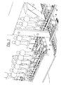
- FIG. 1 shows a metallizing apparatus designated in its entirety as 1. Broadly speaking, this metallizing apparatus is formed by a magnetron sputtering device 2, a preprocessing device 3 and a postprocessing device 4. Extending through each of these devices is a transport device 5. A shunting area 6 is arranged between preprocessing device 3 and PVD device 2 and between PVD device 2 and postprocessing device 4.
- This shunting area serves to compensate for timing differences between the continuously operating preprocessing device 3 and postprocessing device 4 and the semi-continuously operating PVD device 2.
- Transport device 5 is closed and extends in both directions through PVD device 2. Between postprocessing device 4 and preprocessing device 3 the transport device 5 extends through a loading and unloading zone 7.
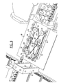
- FIG. 2 This loading and unloading zone is further shown in figure 2.
- transport device 5 has a U-shape at this location.
- rotation devices 20 each comprising a rotating disc 21.
- rotating discs 21 By means of rotating discs 21 it is possible to rotate carrier 15 through an angle of 90°.
- the drive device which is integrated into transport device 5.
- a pushing element 22 drivable by a linear drive element 23 arranged above the rotating disc.
- the objects 24 for processing are placed on carriers 15 on that part of the transport device 5 placed between the two rotation devices 20. This part forms the loading zone 7A.
- the finished products 24 can be taken off the part of transport device 5 preceding rotation device 20. This is the unloading zone 7B.
- Figure 2 further shows how a check gate 25 is placed after the second rotation device 20 for checking the presence of and the location in a plane perpendicular to the direction of movement of the objects for treating.
- the presence detection is important for controlling for instance the lacquer device, so as to prevent an excessive quantity of lacquer being wasted by spraying while no object is passing.
- the location detection serves to prevent objects placed askew on the holders from disrupting the movement of the carriers, whereby objects could become jammed or fall off. This would result in stopping of the process, removal of the objects in question and restarting of the process.
- the first gate 25 placed after the loading station therefore serves mainly to determine whether the objects are placed correctly.
- Such a gate is also placed before the vacuum device.
- the position of the objects is after all critical, and space is limited, this being particularly important in the case of large objects.
- the location of the objects on the carrier may have been changed due to the action of the spraying device.
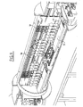
- Figure 3 further shows the construction of transport device 5 at the location of unloading zone 7B.
- Shown in figure 3 is that part. of the transport device which functions as unloading station.
- the transport device comprises two tubular profiles 26 which are provided at regular distances on their underside with bearing units 27, in which are mounted shafts 28.
- a support wheel 29 is arranged on each of the shafts 28.
- two U-shaped profiles 30 which are each fixed against tubular profiles 27.
- a drive chain 31 which is provided with catch elements 32 for moving the carriers 15 along. The chain is guided back again via the underside of the transport device.
- This transport device extends through the entire apparatus according to the invention.
- Carriers 15 are each formed by a carrier body 36, in which are mounted vertically extending shafts 16.
- Carrier body 36 is provided with recesses 18 through which shafts 16 extend and wherein toothed wheels 17 are arranged on the shafts at the location of recesses 18. These toothed wheels 17 serve to drive the shafts in rotation when for instance a gear rack or movable chain is arranged along the sides of profile 26.
- Each of the shafts are provided on their top with a recess 33 on which extension shafts 34 can be placed.
- Product holders adapted to the product for processing which will be described with reference to figure 10, can then be placed on top of extension shafts 34. It is pointed out here that it is possible to use extension shafts 34 of different heights, so that it is possible to adjust the height of the objects for processing on the carriers.
- a part of the profile 30 can otherwise be folded down at the location of unloading station 7B, so that carriers 15 can be taken away.
- a buffer device 6 which provides the synchronization of the essentially continuously operating preprocessing and postprocessing device and the semi-continuously operating vacuum metallization device.
- Buffer device 6 is formed essentially by a frame 35 on which are placed two shafts 37, one of which is drivable by means of a motor 38.
- a chain wheel 39 is placed on each of the shafts 37, wherein a chain 40 is trained around each pair of chain wheels 39.
- Supports 41 are arranged between the two chains 40 for transporting carriers 15.
- Shaft 36 is herein set into intermittent rotation such that supports 41 move intermittently.
- the carriers from UV radiation device 10 are loaded onto the support 41 placed in line with transport device 5, while the carrier then placed in front of the transport device of the vacuum metallization device is simultaneously pushed onto the transport device of the metallization device by means of a pushing device 42.
- a carrier coming from the metallization device is simultaneously pushed onto the relevant support 41 and a carrier placed in front of the transport device of the UV lacquer spraying device 12 is pushed onto the relevant transport device.
- the device in question then moves one full stroke, whereafter this process is repeated.
- Figure 5 shows how a pushing device 42 is arranged for pushing a carrier 15 onto the relevant support 41.
- This pushing device 42 is herein driven by a linear drive member 43.
- This device further shows how the shafts 16 of carrier 15 can be driven in rotation by means of toothed wheels 17, this independently of the linear movement of carrier 15.
- a chain 46 a part of which is arranged parallel to the direction of movement of carrier 15 and which can be driven independently of the transport movement. It will be apparent that it is possible to make use instead of for instance gear racks. These are then arranged fixedly so that the rotation movement is in fact coupled to the transport movement.
- Figure 7 shows in more detail the mechanism with which the movements of supports 41 to the transport device 5 within the vacuum metallization device are executed, and vice versa.
- Figure 8 shows in more detail a part of the drive device for transport of carriers 15 inside the vacuum metallization device.
- the relevant elements are herein mounted on a plate 50, on which are arranged two beams 51 on which guide wheels with guide shafts 52 are mounted. In the middle of each of these beams 51 a guide wheel 52 is further arranged on the other side of the path of the carrier. Finally, support wheels 53 are arranged.
- Drive wheels 55 are also arranged for driving the carrier 15.
- Drive wheels 54 are herein driven by means of belts 55. Both belts 55 are trained round a wheel 56 which is driven by a motor mounted beneath the plate. This drawing also shows that a check gate device is again placed in order to determine whether all objects are present on the carrier.
- FIG 9 shows the construction of the vacuum metallization chamber 4, which otherwise forms the subject-matter of the European patent application 98.203444.9. Here also the same drive device is used. This is further of importance in that plates 57 are arranged to protect the transport device against precipitation of metal. Such plates are otherwise also arranged in the paint spraying devices.
- This figure further shows how the actual targets 58 of the magnetron sputtering device are arranged at two different levels. In combination with the different heights of the extension shafts it is thus possible to determine the height and direction of the metallization process.
- the objects for processing pass twice through the magnetron sputtering device, wherein only one of the two passages is effective.
- the active half of the device is separated from the non-active half of the device by a partition wall 59 of a material on which the sputtered vapour will deposit but which can be removed easily.
- figure 10 shows the construction of product carriers 15.
- the product carriers are placed on top of the extension shafts to carry the products for processing.
- the product carriers are formed by a piece of threaded end which can be placed on the extension shaft, wherein discs provided with internal thread can be placed on the threaded ends, the form and position of which discs can be adapted to the relevant products.
Abstract
Description
- a preprocessing device for performing a preprocessing on the object;
- a PVD device for coating the object under an atmosphere differing from the ambient; and
- a postprocessing device for postprocessing the objects.
- a PVD device for coating the object under a vacuum;
- at least one lock separating the PVD-device from the ambient;
- a transport device which extends though the PVD-device and into the lock;
- wherein the transport device is adapted to transport objects arranged on carriers, and
- the PVD device is adapted for semi-continuous treatment of objects arranged on the carriers.
- a preprocessing device for performing a preprocessing on the object;
- a postprocessing device for postprocessing the objects;
- and that the transport device extends though said at least one lock, the preprocessing device and the postprocessing device.
According to yet another preferred embodiment the transport device has a closed configuration and extends in two directions through the PVD device.
Claims (18)
- Apparatus for applying at least one coating to objects by means of vapour deposition (PVD) under vacuum, comprising:characterized in that the preprocessing device comprises an application device for applying onto the objects for treating a lacquer which cures with radiation, for instance UV or IR radiation, and a device for irradiating the lacquered objects with the relevant radiation.a PVD device for coating the object under a vacuum;at least one lock separating the PVD-device from the ambient;a transport device which extends though the PVD-device and into the lock;wherein the transport device is adapted to transport objects arranged on carriers;the PVD device is adapted for semi-continuous treatment of objects arranged on the carriers;a preprocessing device for performing a preprocessing on the object;a postprocessing device for postprocessing the objects; andwherein the transport device extends though said at least one lock, the preprocessing device and the postprocessing device,
- Apparatus as claimed in claim 1, characterized in that the preprocessing device comprises a blower device for blowing dust from the objects for treating.
- Apparatus as claimed in claim 1 or 2, characterized in that the preprocessing device comprises a surface processing device connected prior to the application device for processing the surface of the objects for treating.
- Apparatus as claimed in any of the foregoing claims, characterized in that the postprocessing device comprises an application device for applying onto the objects for treating a lacquer which cures with radiation, for instance UV radiation, and a device for irradiating the lacquered objects with the relevant radiation.
- Apparatus as claimed in any of the foregoing claims, characterized in that a loading/unloading station is placed between the postprocessing device and the preprocessing device for unloading processed objects and loading objects for processing.
- Apparatus as claimed in one of the preceding claims, characterized in that the carriers are elongate, that object holders are present on the carriers, the object holders are rotatable and the transport device is adapted to move the carriers substantially in the longitudinal direction and to rotate the object holders in the PVD-device.
- Apparatus as claimed in claim 6, characterized in that the PVD device is connected to the ambient by means of a single lock, the transport device extends through the lock and the lock is adapted to feed a carrier simultaneously into and out of the PVD device.
- Apparatus as claimed in claim 7, characterized in that the transport device has a closed configuration and extends in two directions through the PVD device.
- Apparatus as claimed in claim 8, characterized in that a buffer for the carriers is arranged between the preprocessing device and the PVD device.
- Apparatus as claimed in claim 9, characterized in that a buffer for the carriers is arranged between the PVD device and the postprocessing device.
- Apparatus as claimed in claim 9 or 10, characterized in that the buffers are adapted to move the carriers in transverse direction.
- Apparatus as claimed in one the claims 6-11, characterized in that the object holders are interchangeable object holders.
- Apparatus as claimed in claim 12, characterized in that the object holders are placed on vertically extending shafts mounted rotatably in the carriers.
- Apparatus as claimed in claim 13, characterized in that toothed wheels are arranged on the shafts for driving the shafts in rotation.
- Apparatus as claimed in claim 14, characterized in that the toothed wheels are arranged under the top side of the carrier.
- Apparatus as claimed in claim 15, characterized in that the toothed wheels are let into openings arranged in the carrier and the toothed wheels protrude outside the side walls of the carrier.
- Apparatus as claimed in any of the claims 6-16, characterized in that the apparatus is provided with cams for engaging in and rotating the toothed wheels during passage of the carriers.
- Apparatus as claimed in claim 17, characterized in that the cams form part of a drivable chain for causing the shafts to rotate independently of the linear movement of the carrier.
Applications Claiming Priority (3)
| Application Number | Priority Date | Filing Date | Title |
|---|---|---|---|
| NL1010531 | 1998-11-11 | ||
| NL1010531A NL1010531C2 (en) | 1998-11-11 | 1998-11-11 | Device and method for applying a layer to objects by means of vapor deposition (PVD). |
| PCT/NL1999/000689 WO2000028105A1 (en) | 1998-11-11 | 1999-11-11 | Apparatus and method for coating objects through pvd |
Publications (2)
| Publication Number | Publication Date |
|---|---|
| EP1129232A1 EP1129232A1 (en) | 2001-09-05 |
| EP1129232B1 true EP1129232B1 (en) | 2003-10-01 |
Family
ID=19768120
Family Applications (1)
| Application Number | Title | Priority Date | Filing Date |
|---|---|---|---|
| EP99971870A Expired - Lifetime EP1129232B1 (en) | 1998-11-11 | 1999-11-11 | Apparatus for coating objects through pvd |
Country Status (10)
| Country | Link |
|---|---|
| EP (1) | EP1129232B1 (en) |
| AT (1) | ATE251234T1 (en) |
| AU (1) | AU1190600A (en) |
| CA (1) | CA2350492C (en) |
| DE (1) | DE69911804T2 (en) |
| DK (1) | DK1129232T3 (en) |
| ES (1) | ES2204195T3 (en) |
| NL (1) | NL1010531C2 (en) |
| PT (1) | PT1129232E (en) |
| WO (1) | WO2000028105A1 (en) |
Cited By (3)
| Publication number | Priority date | Publication date | Assignee | Title |
|---|---|---|---|---|
| ITMI20090933A1 (en) * | 2009-05-27 | 2010-11-28 | Protec Surface Technologies S R L | APPARATUS FOR DEPOSITION OF COATING FILM |
| US9297064B2 (en) | 2009-01-16 | 2016-03-29 | Marca Machinery, Llc | In-line metallizer assemblies and part-coating conveyor systems incorporating the same |
| US9809878B2 (en) | 2009-01-16 | 2017-11-07 | Marca Machinery, Llc | In-line metallizer assemblies and part-coating conveyor systems incorporating the same |
Families Citing this family (9)
| Publication number | Priority date | Publication date | Assignee | Title |
|---|---|---|---|---|
| WO2003064723A1 (en) * | 2002-01-31 | 2003-08-07 | Jamar Venture Corporation | Production line and method for continuous diffusion surface alloying and diffusion carbide surface alloying |
| CN100408721C (en) * | 2002-08-19 | 2008-08-06 | 乐金电子(天津)电器有限公司 | Heat exchanger surface treatment equipment |
| CA2533524A1 (en) * | 2003-07-24 | 2005-02-17 | Eisenmann Maschinenbau Gmbh & Co. Kg | Device for hardening the coating of an object, consisting of a material that hardens under electromagnetic radiation, more particularly an uv paint or a thermally hardening paint |
| EP2100714B1 (en) | 2008-03-10 | 2013-04-03 | Albéa Services | In- line moulding and metallisation |
| CN101608301B (en) * | 2009-06-24 | 2011-12-07 | 江苏常松机械集团有限公司 | Production line of continuous vacuum plasma evaporation metal composite material |
| ITMI20110432A1 (en) * | 2011-03-18 | 2012-09-19 | Tapematic Spa | MACHINE AND METHOD FOR THE METALLIZATION OF THREE-DIMENSIONAL OBJECTS OF SMALL DIMENSIONS |
| ITMI20121358A1 (en) * | 2012-08-01 | 2014-02-02 | Tapematic Spa | PAINTING AND LINE MACHINE FOR FINISHING THREE-DIMENSIONAL OBJECTS OF SMALL DIMENSIONS AND RELATED METHODS |
| ES2747351T3 (en) * | 2012-10-19 | 2020-03-10 | Marca Machinery Llc | Inline metallizer assemblies and part coating conveyor systems incorporating them |
| FR3042698A1 (en) * | 2015-10-22 | 2017-04-28 | Les Laboratoires Osteal Medical | SUPPORTING DEVICES FOR SUPPORTING IMPLANTS OR PROSTHESES |
Family Cites Families (8)
| Publication number | Priority date | Publication date | Assignee | Title |
|---|---|---|---|---|
| DE2109061A1 (en) * | 1970-02-27 | 1971-09-09 | Varian Associates | Vacuum coating of multiface substrate |
| JPS53130779A (en) * | 1977-04-20 | 1978-11-15 | Mitsubishi Rayon Co Ltd | Molded metallized plastic article and its manufacture |
| JPS60184678A (en) * | 1984-03-02 | 1985-09-20 | Canon Inc | Vacuum treating device |
| CA1264025A (en) * | 1987-05-29 | 1989-12-27 | James A.E. Bell | Apparatus and process for coloring objects by plasma coating |
| JPH04176867A (en) * | 1990-11-13 | 1992-06-24 | Kawasaki Steel Corp | Dust-proof device of multistage type vacuum differential pressure chamber |
| JP3199516B2 (en) * | 1993-05-14 | 2001-08-20 | 株式会社神戸製鋼所 | Ion plating apparatus having a rotating mechanism for workpiece |
| JPH0863747A (en) * | 1994-08-22 | 1996-03-08 | Mitsubishi Chem Corp | Production of magnetic recording medium |
| WO1997028290A1 (en) * | 1996-01-31 | 1997-08-07 | Optical Coating Laboratory, Inc. | Multi-chamber continuous sputter coating system |
-
1998
- 1998-11-11 NL NL1010531A patent/NL1010531C2/en not_active IP Right Cessation
-
1999
- 1999-11-11 WO PCT/NL1999/000689 patent/WO2000028105A1/en active IP Right Grant
- 1999-11-11 PT PT99971870T patent/PT1129232E/en unknown
- 1999-11-11 AU AU11906/00A patent/AU1190600A/en not_active Abandoned
- 1999-11-11 EP EP99971870A patent/EP1129232B1/en not_active Expired - Lifetime
- 1999-11-11 AT AT99971870T patent/ATE251234T1/en active
- 1999-11-11 ES ES99971870T patent/ES2204195T3/en not_active Expired - Lifetime
- 1999-11-11 DE DE69911804T patent/DE69911804T2/en not_active Expired - Lifetime
- 1999-11-11 CA CA002350492A patent/CA2350492C/en not_active Expired - Fee Related
- 1999-11-11 DK DK99971870T patent/DK1129232T3/en active
Cited By (5)
| Publication number | Priority date | Publication date | Assignee | Title |
|---|---|---|---|---|
| US9297064B2 (en) | 2009-01-16 | 2016-03-29 | Marca Machinery, Llc | In-line metallizer assemblies and part-coating conveyor systems incorporating the same |
| US9809878B2 (en) | 2009-01-16 | 2017-11-07 | Marca Machinery, Llc | In-line metallizer assemblies and part-coating conveyor systems incorporating the same |
| US10060027B2 (en) | 2009-01-16 | 2018-08-28 | Marca Machinery, Llc | In-line metallizer assemblies and part-coating conveyor systems incorporating the same |
| ITMI20090933A1 (en) * | 2009-05-27 | 2010-11-28 | Protec Surface Technologies S R L | APPARATUS FOR DEPOSITION OF COATING FILM |
| EP2256233A1 (en) * | 2009-05-27 | 2010-12-01 | Protec Surface Technologies S.r.L. | An apparatus for deposition of coating films |
Also Published As
| Publication number | Publication date |
|---|---|
| ATE251234T1 (en) | 2003-10-15 |
| EP1129232A1 (en) | 2001-09-05 |
| DE69911804T2 (en) | 2004-08-12 |
| WO2000028105A1 (en) | 2000-05-18 |
| DE69911804D1 (en) | 2003-11-06 |
| DK1129232T3 (en) | 2004-02-09 |
| ES2204195T3 (en) | 2004-04-16 |
| NL1010531C2 (en) | 2000-05-15 |
| PT1129232E (en) | 2004-01-30 |
| CA2350492C (en) | 2008-09-23 |
| CA2350492A1 (en) | 2000-05-18 |
| AU1190600A (en) | 2000-05-29 |
Similar Documents
| Publication | Publication Date | Title |
|---|---|---|
| US9487857B2 (en) | Machine for painting and line for finishing small three-dimensional objects and related methods | |
| EP1129232B1 (en) | Apparatus for coating objects through pvd | |
| JP3339585B2 (en) | Method for introducing and deriving products, especially vehicle bodies, product surface treatment devices and systems | |
| US10060027B2 (en) | In-line metallizer assemblies and part-coating conveyor systems incorporating the same | |
| US6132562A (en) | Method and device for transporting cylindrical substrates to be coated | |
| US3931789A (en) | Vapor deposition apparatus | |
| US6112389A (en) | Transport device and pallets for containers | |
| US6319563B1 (en) | Golf ball painting method | |
| EP3441148B1 (en) | Printing and painting device and method. | |
| US5645895A (en) | Method for painting a vehicle body | |
| US4503086A (en) | Device and method for uniformly curing uv photoreactive overvarnish layers | |
| KR101759033B1 (en) | Apparatus for coating the inner surface of a container | |
| US6558468B2 (en) | Conveyance apparatus for coating | |
| US5326442A (en) | Apparatus for the galvanic treatment of articles | |
| EP2500448B1 (en) | Machine and method for metallization of three-dimensional objects of small sizes | |
| US4781112A (en) | Apparatus for printing hollow containers | |
| US9809878B2 (en) | In-line metallizer assemblies and part-coating conveyor systems incorporating the same | |
| US6837933B2 (en) | Apparatus for surface coating of small parts | |
| JPS6311547A (en) | Method and apparatus for producing surface treated glass container | |
| JP4701079B2 (en) | Coating film forming device | |
| JP4206361B2 (en) | SUBSTRATE CONVEYING DEVICE AND PROCESSED BODY DECORATION METHOD | |
| KR102353897B1 (en) | Deposition System for menufacturing cosmetic vessel | |
| KR200199543Y1 (en) | Conveyor for transfer painting a thing | |
| KR20230028624A (en) | Apparatus for menufacturing cosmetic vessel | |
| JPS6323764A (en) | Method and device for coating and curing vessel |
Legal Events
| Date | Code | Title | Description |
|---|---|---|---|
| PUAI | Public reference made under article 153(3) epc to a published international application that has entered the european phase |
Free format text: ORIGINAL CODE: 0009012 |
|
| 17P | Request for examination filed |
Effective date: 20010530 |
|
| AK | Designated contracting states |
Kind code of ref document: A1 Designated state(s): AT BE CH CY DE DK ES FI FR GB GR IE IT LI LU MC NL PT SE |
|
| AX | Request for extension of the european patent |
Free format text: AL PAYMENT 20010529;LT PAYMENT 20010529;LV PAYMENT 20010529;MK PAYMENT 20010529;RO PAYMENT 20010529;SI PAYMENT 20010529 |
|
| 17Q | First examination report despatched |
Effective date: 20020320 |
|
| GRAH | Despatch of communication of intention to grant a patent |
Free format text: ORIGINAL CODE: EPIDOS IGRA |
|
| RTI1 | Title (correction) |
Free format text: APPARATUS FOR COATING OBJECTS THROUGH PVD |
|
| GRAH | Despatch of communication of intention to grant a patent |
Free format text: ORIGINAL CODE: EPIDOS IGRA |
|
| GRAA | (expected) grant |
Free format text: ORIGINAL CODE: 0009210 |
|
| AK | Designated contracting states |
Kind code of ref document: B1 Designated state(s): AT BE CH CY DE DK ES FI FR GB GR IE IT LI LU MC NL PT SE |
|
| AX | Request for extension of the european patent |
Extension state: AL LT LV MK RO SI |
|
| REG | Reference to a national code |
Ref country code: GB Ref legal event code: FG4D |
|
| REG | Reference to a national code |
Ref country code: CH Ref legal event code: EP |
|
| REG | Reference to a national code |
Ref country code: IE Ref legal event code: FG4D |
|
| REG | Reference to a national code |
Ref country code: CH Ref legal event code: NV Representative=s name: ARNOLD & SIEDSMA AG |
|
| REF | Corresponds to: |
Ref document number: 69911804 Country of ref document: DE Date of ref document: 20031106 Kind code of ref document: P |
|
| REG | Reference to a national code |
Ref country code: GR Ref legal event code: EP Ref document number: 20030404332 Country of ref document: GR |
|
| PGFP | Annual fee paid to national office [announced via postgrant information from national office to epo] |
Ref country code: LU Payment date: 20031126 Year of fee payment: 5 |
|
| PGFP | Annual fee paid to national office [announced via postgrant information from national office to epo] |
Ref country code: MC Payment date: 20031127 Year of fee payment: 5 Ref country code: GR Payment date: 20031127 Year of fee payment: 5 |
|
| PGFP | Annual fee paid to national office [announced via postgrant information from national office to epo] |
Ref country code: CY Payment date: 20031210 Year of fee payment: 5 |
|
| REG | Reference to a national code |
Ref country code: SE Ref legal event code: TRGR |
|
| REG | Reference to a national code |
Ref country code: DK Ref legal event code: T3 |
|
| LTIE | Lt: invalidation of european patent or patent extension |
Effective date: 20031001 |
|
| REG | Reference to a national code |
Ref country code: ES Ref legal event code: FG2A Ref document number: 2204195 Country of ref document: ES Kind code of ref document: T3 |
|
| ET | Fr: translation filed | ||
| PLBE | No opposition filed within time limit |
Free format text: ORIGINAL CODE: 0009261 |
|
| STAA | Information on the status of an ep patent application or granted ep patent |
Free format text: STATUS: NO OPPOSITION FILED WITHIN TIME LIMIT |
|
| 26N | No opposition filed |
Effective date: 20040702 |
|
| PG25 | Lapsed in a contracting state [announced via postgrant information from national office to epo] |
Ref country code: LU Free format text: LAPSE BECAUSE OF NON-PAYMENT OF DUE FEES Effective date: 20041111 Ref country code: CY Free format text: LAPSE BECAUSE OF NON-PAYMENT OF DUE FEES Effective date: 20041111 |
|
| PG25 | Lapsed in a contracting state [announced via postgrant information from national office to epo] |
Ref country code: MC Free format text: LAPSE BECAUSE OF NON-PAYMENT OF DUE FEES Effective date: 20041130 |
|
| PG25 | Lapsed in a contracting state [announced via postgrant information from national office to epo] |
Ref country code: GR Free format text: LAPSE BECAUSE OF NON-PAYMENT OF DUE FEES Effective date: 20050602 |
|
| PG25 | Lapsed in a contracting state [announced via postgrant information from national office to epo] |
Ref country code: PT Free format text: LAPSE BECAUSE OF NON-PAYMENT OF DUE FEES Effective date: 20050811 |
|
| REG | Reference to a national code |
Ref country code: PT Ref legal event code: MM4A Effective date: 20050811 |
|
| PG25 | Lapsed in a contracting state [announced via postgrant information from national office to epo] |
Ref country code: PT Free format text: LAPSE BECAUSE OF NON-PAYMENT OF DUE FEES Effective date: 20031111 |
|
| PGFP | Annual fee paid to national office [announced via postgrant information from national office to epo] |
Ref country code: SE Payment date: 20111124 Year of fee payment: 13 Ref country code: FI Payment date: 20111025 Year of fee payment: 13 Ref country code: DK Payment date: 20111125 Year of fee payment: 13 |
|
| REG | Reference to a national code |
Ref country code: DE Ref legal event code: R097 Ref document number: 69911804 Country of ref document: DE Ref country code: DE Ref legal event code: R040 Ref document number: 69911804 Country of ref document: DE |
|
| REG | Reference to a national code |
Ref country code: DK Ref legal event code: EBP |
|
| PG25 | Lapsed in a contracting state [announced via postgrant information from national office to epo] |
Ref country code: SE Free format text: LAPSE BECAUSE OF NON-PAYMENT OF DUE FEES Effective date: 20121112 |
|
| PG25 | Lapsed in a contracting state [announced via postgrant information from national office to epo] |
Ref country code: FI Free format text: LAPSE BECAUSE OF NON-PAYMENT OF DUE FEES Effective date: 20121111 |
|
| PG25 | Lapsed in a contracting state [announced via postgrant information from national office to epo] |
Ref country code: DK Free format text: LAPSE BECAUSE OF NON-PAYMENT OF DUE FEES Effective date: 20121130 |
|
| REG | Reference to a national code |
Ref country code: DE Ref legal event code: R040 Ref document number: 69911804 Country of ref document: DE Effective date: 20130110 |
|
| REG | Reference to a national code |
Ref country code: FR Ref legal event code: PLFP Year of fee payment: 17 |
|
| PGFP | Annual fee paid to national office [announced via postgrant information from national office to epo] |
Ref country code: DE Payment date: 20151124 Year of fee payment: 17 Ref country code: IE Payment date: 20151125 Year of fee payment: 17 Ref country code: CH Payment date: 20151126 Year of fee payment: 17 Ref country code: GB Payment date: 20151130 Year of fee payment: 17 |
|
| PGFP | Annual fee paid to national office [announced via postgrant information from national office to epo] |
Ref country code: AT Payment date: 20151125 Year of fee payment: 17 Ref country code: FR Payment date: 20151126 Year of fee payment: 17 Ref country code: ES Payment date: 20151125 Year of fee payment: 17 Ref country code: NL Payment date: 20151124 Year of fee payment: 17 Ref country code: BE Payment date: 20151124 Year of fee payment: 17 |
|
| PGFP | Annual fee paid to national office [announced via postgrant information from national office to epo] |
Ref country code: IT Payment date: 20151127 Year of fee payment: 17 |
|
| PG25 | Lapsed in a contracting state [announced via postgrant information from national office to epo] |
Ref country code: BE Free format text: LAPSE BECAUSE OF NON-PAYMENT OF DUE FEES Effective date: 20161130 |
|
| REG | Reference to a national code |
Ref country code: DE Ref legal event code: R119 Ref document number: 69911804 Country of ref document: DE |
|
| REG | Reference to a national code |
Ref country code: CH Ref legal event code: PL |
|
| REG | Reference to a national code |
Ref country code: NL Ref legal event code: MM Effective date: 20161201 |
|
| REG | Reference to a national code |
Ref country code: AT Ref legal event code: MM01 Ref document number: 251234 Country of ref document: AT Kind code of ref document: T Effective date: 20161111 |
|
| GBPC | Gb: european patent ceased through non-payment of renewal fee |
Effective date: 20161111 |
|
| PG25 | Lapsed in a contracting state [announced via postgrant information from national office to epo] |
Ref country code: LI Free format text: LAPSE BECAUSE OF NON-PAYMENT OF DUE FEES Effective date: 20161130 Ref country code: CH Free format text: LAPSE BECAUSE OF NON-PAYMENT OF DUE FEES Effective date: 20161130 |
|
| REG | Reference to a national code |
Ref country code: IE Ref legal event code: MM4A |
|
| REG | Reference to a national code |
Ref country code: FR Ref legal event code: ST Effective date: 20170731 |
|
| PG25 | Lapsed in a contracting state [announced via postgrant information from national office to epo] |
Ref country code: AT Free format text: LAPSE BECAUSE OF NON-PAYMENT OF DUE FEES Effective date: 20161111 |
|
| PG25 | Lapsed in a contracting state [announced via postgrant information from national office to epo] |
Ref country code: NL Free format text: LAPSE BECAUSE OF NON-PAYMENT OF DUE FEES Effective date: 20161201 |
|
| PG25 | Lapsed in a contracting state [announced via postgrant information from national office to epo] |
Ref country code: IT Free format text: LAPSE BECAUSE OF NON-PAYMENT OF DUE FEES Effective date: 20161111 Ref country code: FR Free format text: LAPSE BECAUSE OF NON-PAYMENT OF DUE FEES Effective date: 20161130 |
|
| PG25 | Lapsed in a contracting state [announced via postgrant information from national office to epo] |
Ref country code: IE Free format text: LAPSE BECAUSE OF NON-PAYMENT OF DUE FEES Effective date: 20161111 Ref country code: GB Free format text: LAPSE BECAUSE OF NON-PAYMENT OF DUE FEES Effective date: 20161111 Ref country code: DE Free format text: LAPSE BECAUSE OF NON-PAYMENT OF DUE FEES Effective date: 20170601 |
|
| REG | Reference to a national code |
Ref country code: BE Ref legal event code: MM Effective date: 20161130 |
|
| PG25 | Lapsed in a contracting state [announced via postgrant information from national office to epo] |
Ref country code: ES Free format text: LAPSE BECAUSE OF FAILURE TO SUBMIT A TRANSLATION OF THE DESCRIPTION OR TO PAY THE FEE WITHIN THE PRESCRIBED TIME-LIMIT Effective date: 20031001 |
|
| REG | Reference to a national code |
Ref country code: ES Ref legal event code: FD2A Effective date: 20181116 |
|
| RIC2 | Information provided on ipc code assigned after grant |
Ipc: B65G 35/06 20060101ALI20000519BHEP Ipc: B65G 47/244 20060101ALI20000519BHEP Ipc: B05D 5/06 20060101ALI20000519BHEP Ipc: C23C 14/56 20060101AFI20000519BHEP Ipc: B65G 17/00 20060101ALI20000519BHEP Ipc: C23C 14/50 20060101ALI20000519BHEP |
|
| PG25 | Lapsed in a contracting state [announced via postgrant information from national office to epo] |
Ref country code: ES Free format text: LAPSE BECAUSE OF FAILURE TO SUBMIT A TRANSLATION OF THE DESCRIPTION OR TO PAY THE FEE WITHIN THE PRESCRIBED TIME-LIMIT Effective date: 20161112 |