EP1128992B1 - Foldable separating device - Google Patents
Foldable separating device Download PDFInfo
- Publication number
- EP1128992B1 EP1128992B1 EP00965793A EP00965793A EP1128992B1 EP 1128992 B1 EP1128992 B1 EP 1128992B1 EP 00965793 A EP00965793 A EP 00965793A EP 00965793 A EP00965793 A EP 00965793A EP 1128992 B1 EP1128992 B1 EP 1128992B1
- Authority
- EP
- European Patent Office
- Prior art keywords
- separating device
- hinge
- strut
- extension
- fabric
- Prior art date
- Legal status (The legal status is an assumption and is not a legal conclusion. Google has not performed a legal analysis and makes no representation as to the accuracy of the status listed.)
- Expired - Lifetime
Links
Images


Classifications
-
- B—PERFORMING OPERATIONS; TRANSPORTING
- B60—VEHICLES IN GENERAL
- B60R—VEHICLES, VEHICLE FITTINGS, OR VEHICLE PARTS, NOT OTHERWISE PROVIDED FOR
- B60R5/00—Compartments within vehicle body primarily intended or sufficiently spacious for trunks, suit-cases, or the like
- B60R5/04—Compartments within vehicle body primarily intended or sufficiently spacious for trunks, suit-cases, or the like arranged at rear of vehicle
-
- B—PERFORMING OPERATIONS; TRANSPORTING
- B60—VEHICLES IN GENERAL
- B60R—VEHICLES, VEHICLE FITTINGS, OR VEHICLE PARTS, NOT OTHERWISE PROVIDED FOR
- B60R21/00—Arrangements or fittings on vehicles for protecting or preventing injuries to occupants or pedestrians in case of accidents or other traffic risks
- B60R21/02—Occupant safety arrangements or fittings, e.g. crash pads
- B60R21/06—Safety nets, transparent sheets, curtains, or the like, e.g. between occupants and glass
Description
Aus der DE-A-197 30 801 ist ein einfaches Sicherheitsnetz bekannt, dass dazu dient den Laderaum eines PKW von dem eigentlichen Fahrgastraum abzutrennen. Das Sicherheitsnetz wird vor der Öffnung aufgespannt, die zwischen der Oberkante der Rücksitzlehne oder den Vordersitzlehnen und dem Dachhimmel begrenzt ist. Durch diese Öffnung könnten bei einem Unfall Gegenstände aus dem Laderaum in den Fahrgastraum geschleudert werden und dort Menschen verletzen. Dies zu verhindern ist Zweck des bekannten Sicherheitsnetzes.DE-A-197 30 801 is a simple safety net known to serve the cargo space of a car from separate the actual passenger compartment. The safety net is stretched in front of the opening between the Upper edge of the rear seat backrest or the front seat backrests and the headlining is limited. Through this opening in the event of an accident, objects from the hold into the passenger compartment are hurled and hurt people there. To prevent this is the purpose of the known safety net.
Das bekannte Sicherheitsnetz ist an seiner oberen und an seiner unteren Kante jeweils mit einer durchgehenden, rohrförmigen Strebe versehen. Die obere Strebe wird mit seitlichen verschiebbaren Verankerungsgliedern in entsprechende T-nutenartige Einhängetasche der Karosserie eingehängt, während die untere rohrförmige Strebe mit einfachen Bändern am Karosserieboden befestigt ist. Der Vorteil dieses bekannten Sicherheitsnetzes besteht darin, dass es wegen des fehlenden Gehäuses relativ leicht ist. Im Nichtgebrauchszustand kann das Sicherheitsnetz auf eine der beiden Streben aufgewickelt werden und nimmt dann entsprechend wenig Platz ein. Wegen der enormen Länge der Streben ist es allerdings nur schwer im Fahrzeug selbst zu verstauen und muss im Allgemeinen bei Nichtgebrauch häufig in der Garage aufgehoben werden.The well-known safety net is at its top and at its lower edge with a continuous, tubular strut provided. The upper strut comes with laterally displaceable anchoring members in corresponding T-slot-like hanger pocket attached to the body, while the lower tubular strut with simple Straps is attached to the body floor. The advantage of this known security network is that it is because of the missing housing is relatively light. When not in use can the safety net on one of the two Struts are wound up and then takes accordingly little space. Because of the enormous length of the struts it is however difficult to store in the vehicle itself and generally needs to be in the garage when not in use To get picked up.
Ausgehend hiervon ist es Aufgabe der Erfindung ein einfaches Sicherheitsnetz zu schaffen, das auch bei Nichtgebrauch leicht im Auto aufbewahrt werden kann.Based on this, it is an object of the invention to create a simple safety net, even when not in use can be easily stored in the car.
Die US-A-5,427,846 zeigt ein Trennnetz für den Laderaum eines Pick-Up. Zu dem Trennnetz gehört das eigentliche Netzgebilde, das mit Hilfe von zwei oder drei Streben quer über den Laderaum aufgespannt gehalten wird. Jede der Streben enthält endseitig Stützplatten, die gegen die Innenseite der Ladebordwand angepresst werden. Hierzu sitzt wenigstens einer der Stützplatten jeder Strebe, an einem teleskopstück, das in der Strebe verschiebbar ist. Mit Hilfe einer Feder, die sich einerseits in dem Rohr und andererseits an dem Teleskopstütz abstützt, wird die betreffende Stützplatte mit Kraft gegen die Ladebordwand gedrückt.US-A-5,427,846 shows a separation net for the cargo space of a pick-up. The actual network belongs to the separation network Network structure that crosses with the help of two or three struts is kept stretched over the hold. Each of the struts contains support plates at the end, which are against the inside be pressed against the tail lift. At least this sits one of the support plates of each strut, on a telescopic piece, that is slidable in the strut. With help a spring that is on the one hand in the tube and on the other hand is supported on the telescopic support, the relevant Support plate pressed against the tail lift with force.
Die Widerlager der Feder bilden jeweils Stifte, die durch die Feder hindurchführen. Durch Drehen des Teleskopstücks können die Stifte zusätzlich längs der Feder verstellt werden.The abutments of the spring each form pins pass through the spring. By turning the telescopic piece the pins can also be adjusted along the spring become.
Diese Aufgabe wird erfindungsgemäß durch die Trenneinrichtung mit den Merkmalen des Anspruches 1 gelöst.This object is achieved by the separating device solved with the features of claim 1.
Die neue herausnehmbare Trenneinrichtung weist eine im Gebrauch obere und eine im Gebrauch untere Strebe auf, zwischen denen sich im Gebrauchszustand ein im Wesentlichen undehnbares Flächengebilde erstreckt, das mit der oberen und der unteren Strebe verbunden ist. Um bei Nichtgebrauch den Platzbedarf noch weiter zu verringern, sind die obere und die untere Strebe in ihrer wirksamen Länge auf mindestens 30% ihrer maximalen Länge zu verkürzen. Dadurch erhält das aufgerollte Paket der nichtgebrauchten Trenneinrichtung eine geringere Länge und lässt sich ohne Weiteres im Kofferraum unterbringen.The new removable separator has an in Use upper and one lower strut in use, between which there is essentially one in use inextensible fabric that extends with the upper and the lower strut is connected. To when not in use The upper ones are to further reduce the space requirement and the lower strut in its effective length to at least Shorten 30% of their maximum length. This gives the rolled up package of the unused separation device a shorter length and can easily be Store in the trunk.
Eine besonders einfache Maßnahme, die Verkürzung der effektiven Länge zu erreichen, besteht darin, die Streben wenigstens einmal faltbar auszuführen. Hierzu kann die obere und die untere Strebe jeweils ein Scharnier mit einer Scharnierachse enthalten, wodurch die jeweilige Strebe in zwei Strebenabschnitte aufgeteilt wird.A particularly simple measure, the shortening of the to achieve effective length is the struts to be foldable at least once. For this, the upper one and the lower strut each has a hinge with a Hinge axis included, whereby the respective strut in two strut sections is divided.
Eine maximale Verringerung der effektiven Länge wird erreicht, wenn die Strebenabschnitte jeder Strebe untereinander gleich lang sind.There will be a maximum reduction in effective length reached when the strut sections of each strut with each other are the same length.
Um beim Aufwickeln des Flächengebildes auf die zusammengelegten Strebenabschnitte keine Spannungen in dem Flächengebilde zu erzeugen, sind die Scharniere in der Weise aufeinander ausgerichtet, dass bei aufgespannter Trenneinrichtung die beiden Scharniere auf einer Geraden liegen, die auf den beiden zueinander parallelen Streben senkrecht steht.To when winding the fabric onto the folded Strut sections no tension in the fabric to produce, the hinges are in the way aligned with each other that with the separating device clamped the two hinges lie on a straight line, which are perpendicular to the two parallel struts stands.
Damit die Streben im Falle eines Crashs, wenn Gegenstände aus dem Laderaum gegen die Trenneinrichtung geschleudert werden, ein möglichst großes Widerstandsmoment erzeugen, sind die Scharnierachsen bei aufgespannter Trenneinrichtung vorzugsweise horizontal ausgerichtet, d.h. die Scharnierachsen zeigen in Richtung parallel zur Fahrzeuglängsachse.So the struts in the event of a crash when objects from the hold against the disconnecting device are thrown, the greatest possible section modulus generate, are the hinge axes when the separating device is clamped preferably aligned horizontally, i.e. the Hinge axes point in the direction parallel to the vehicle's longitudinal axis.
Darüber hinaus ist es zweckmäßig die Scharnierachse bezüglich der dem jeweiligen Scharnier benachbarten Strebenabschnitte derart versetzt anzuordnen, dass sich beim Falten die Strebenabschnitte ohne Weiteres in eine Parallellage zueinander bringen lassen.In addition, it is useful the hinge axis with respect to the strut sections adjacent to the respective hinge to be arranged so that the Easily fold the strut sections into a parallel position get brought together.
Um hierbei eine Klemm- oder Quetschgefahr in der Nähe der Scharniere auszuschließen, ist der Versatz vorteilhafterweise groß, damit neben dem Scharnier ein Zwischenraum von 1,5 bis 2 cm verbleibt, wenn die Strebenabschnitte an ihrem von dem Scharnier abliegenden Ende aneinander stoßen.To avoid pinching or crushing nearby to exclude the hinges, the offset is advantageous large so that there is a space next to the hinge of 1.5 to 2 cm remains when the strut sections are on abut their end remote from the hinge.
Die Anordnung wird sehr robust und kostengünstig herstellbar, wenn das Scharnier ein einfaches Scharnier mit lediglich einer Scharnierachse ist.The arrangement is very robust and inexpensive to manufacture, if the hinge is a simple hinge with is only a hinge axis.
Das Scharnier setzt sich im einfachsten Falle aus zwei Scharnierlaschen zusammen, die durch einen Scharnierbolzen unlösbar miteinander verbunden sind. Jede Scharnierlasche trägt einen Fortsatz, über den die Scharnierlasche mit den jeweiligen Strebenabschnitt starr und unlösbar verbunden ist. Die Fortsätze an den Scharnierlaschen sind so ausgerichtet, dass in einer Stellung die Scharnierlaschen auf einer Geraden liegen, die gegenüber der Scharnierachse seitlich versetzt ist, und zwar gemessen in einer Ebene, auf der die Scharnierachse senkrecht steht.In the simplest case, the hinge consists of two Hinge tabs put together by a hinge pin are inextricably linked. Each hinge tab carries an extension over which the hinge plate with the each strut section rigidly and permanently connected is. The extensions on the hinge tabs are aligned that the hinge tabs open in one position a straight line lying opposite the hinge axis is offset laterally, measured in one plane, on which the hinge axis is vertical.
Die Handhabung der Trenneinrichtung wird wesentlich vereinfacht, wenn das Scharnier in wenigstens einer Stellung verriegelbar ist. Hierdurch wird die Strebe, die sich aus den Strebenabschnitten zusammensetzt wie eine starre, durchgehenden Strebe handhabbar, die sich leicht in den karosserieseitigen Aufnahmen einhängen lässt. Die Verriegelung kann eine rastbare Verriegelung sein oder eine formschlüssig verriegelbare Verriegelung. Die Stellung, in der die Verriegelung auftritt, ist zweckmäßiger Weise die Stellung, in der die Strebe maximal gestreckt ist. The handling of the separator becomes essential simplified when the hinge is in at least one position can be locked. This will make the strut stand out composed of the strut sections like a rigid, continuous strut manageable, which is easy in the body-side recordings. The lock can be a snap lock or a form-fit lockable lock. The position in which the locking occurs, the position is expediently in which the strut is stretched to the maximum.
Die Scharnierlaschen können zum Zwecke der Verriegelung Öffnungen enthalten, die in der Verriegelungsstellung miteinander fluchten, wobei zur Verriegelung ein in die Öffnungen einschiebbarer Bolzen vorgesehen ist. Der Bolzen ist mittels einer Feder in die vorgeschobene Stellung vorgespannt, damit selbsttätig das Einrasten erfolgt, wenn die gewünschte gestreckte Stellung erreicht ist.The hinge tabs can be used for locking purposes Openings included in the locked position aligned with each other, for locking in the Openings insertable bolt is provided. The bolt is biased into the advanced position by a spring, so that it engages automatically when the Desired stretched position is reached.
Um den Bolzen zu entriegeln, ist ein Betätigungsglied vorgesehen, das im Bereich einer der beiden Scharnierlaschen gelagert ist und dazu dient, den Bolzen aus wenigstens einer der beiden Öffnungen zurückzudrücken.To unlock the bolt, there is an actuator provided that in the area of one of the two hinge tabs is stored and serves to at least remove the bolt push one of the two openings back.
Um die Knickfestigkeit der Scharnierlaschen am Übergang zu den Fortsätzen, auf denen die Strebenabschnitte stecken, zu verbessern, ist die Scharnierlasche mit einer Sicke versehen, die sich in den Fortsatz hinein erstreckt.The kink resistance of the hinge tabs at the transition to the extensions on which the strut sections stuck to improve, the hinge bracket with one Provide beading that extends into the extension.
Damit bei jeweils gestreckter Strebe die Strebenabschnitte in gerader Linie zueinander verlaufen, ist der Fortsatz jeder Scharnierlasche geringfügig abgekröpft. Wenn die Abkröpfung an beiden Scharnierlaschen betragsmäßig gleich ist, genügt eine einzige Art von Scharnierlaschen, um das Scharnier aufzubauen. Hierdurch vereinfacht sich der fertigungstechnische Aufwand, weil nur ein Werkzeug zum Stanzbiegen der Scharnierlasche erforderlich ist.This means the strut sections when the strut is stretched run in a straight line to each other is the The extension of each hinge bracket is slightly bent. If the amount of offset on both hinge tabs is the same, a single type of hinge bracket is sufficient, to build the hinge. This simplifies the manufacturing effort, because only one tool for Punching the hinge bracket is required.
Zwecks unlösbarer Verbindung der Scharnierlasche mit den Strebenabschnitten enthält die Scharnierlasche in ihrem Rand Ausnehmungen oder Kerben, die vorzugsweise sägezahnförmig gestaltet sind.For the permanent connection of the hinge bracket with the strut sections contain the hinge tab in their Edge recesses or notches, which are preferably sawtooth-shaped are designed.
Um das Scharnier und die Verriegelungseinrichtung gegen Eindringen von Schmutz zu schützen, sowie die Federteile gegen Beschädigung, ist jeder Scharnierlasche eine schalenförmige Abdeckung zugeordnet.To counter the hinge and locking device Protect the ingress of dirt, as well as the spring parts against damage, each hinge bracket is one assigned cupped cover.
Eine sehr hohe Festigkeit der Streben gegen Durchbiegen bei geringem Gewicht wird erreicht, wenn der Strebenabschnitt rohrförmig ist. Im einfachsten Falle ist jeder Strebenabschnitt ein zylindrisches Rohr, das in der Nähe des Scharniers im Querschnitt abgeflacht ist, wobei in dem abgeflachten Teil, der dadurch eine ovale Querschnittsgestalt bekommt der Fortsatz eingesteckt ist.A very high strength of the struts against bending light weight is achieved when the strut section is tubular. In the simplest case, everyone is Strut section a cylindrical tube that is nearby of the hinge is flattened in cross section, in which flattened part, which thereby has an oval cross-sectional shape the extension gets inserted.
Die axiale Sicherung des jeweiligen Strebenabschnittes auf dem Fortsatz der Scharnierlasche geschieht, indem der Strebenabschnitt auf dem Fortsatz verstemmt wird, wobei Material des Strebenabschnitts in die randseitigen Ausnehmungen der jeweiligen Lasche gedrängt wird.The axial securing of the respective strut section happens on the extension of the hinge tab by the Strut section is caulked on the extension, wherein Material of the strut section in the marginal recesses the respective tab is pushed.
Die Strebenabschnitte bestehen zweckmäßigerweise aus einem energieverzehrend verformbaren Material, wodurch bei einem Auffahrunfall die Belastungsspitzen an dem Flächengebilde vermindert werden.The strut sections expediently consist of an energy-consuming deformable material, which makes in a rear-end collision, the load peaks on the fabric can be reduced.
Das Flächengebilde kann aus einem Netz oder aus einer gelochten Folie bestehen.The fabric can be from a network or from a perforated film exist.
Die Streben bzw. Strebenabschnitte sind an dem Flächengebilde unverdrehbar befestigt, um die Handhabung zu vereinfachen. Darüber hinaus sollten im Sinne einer einfachen Handhabung die Strebenabschnitte noch an dem Flächengebilde unverschieblich befestigt sein.The struts or strut sections are on the fabric non-rotatably attached to handling simplify. In addition, in the sense of a simple Handling the strut sections still on the fabric be fixed immovably.
Ein Einklemmen des Flächengebildes beim Zusammenfalten und eine einfachere Herstellbarkeit wird erreicht, wenn das Flächengebilde im Bereich des jeweiligen Scharniers eine Aussparung enthält.A pinching of the fabric when folding and easier manufacturability is achieved if that Flat structures in the area of the respective hinge one Contains recess.
Der erfindungsgemäßen Trenneinrichtung ist eine Sicherungseinrichtung zugeordnet, die dazu dient die Trenneinrichtung in ihrer Verstaustellung zu sichern, damit sie als kompakte Einheit handhabbar ist, ohne dass die Gefahr besteht, dass es sich in die Trenneinrichtung auseinanderwickelt oder auffaltet.The separating device according to the invention is a safety device assigned, which serves the separation device secure in their stowage so that it can be used as a compact unit can be handled without the risk of that it unwraps into the separator or unfolds.
Die Verstaueinrichtung ist vorteilhafter Weise von einer Tasche gebildet, die an der Trenneinrichtung unverlierbar befestigt ist. Die Tasche kann aus zwei flexiblen Taschenwänden bestehen, von denen jede sich längs eines Strebenabschnittes einer der beiden Streben erstreckt und von denen jede im Bereich des betreffenden Strebenabschnittes befestigt ist. Dadurch wird erreicht, dass sich eine vollständige Tasche ergibt, wenn die Trenneinrichtung nach dem Zusammenfalten der beiden Streben über eine der beiden gefalteten Streben aufgewickelt wird. Durch Verbinden der Taschenwände miteinander wird ein Freikommen des Wickels aus der Tasche verhindert.The storage device is advantageously of a bag formed, which is captive on the separator is attached. The bag can be made out of two flexible ones There are pocket walls, each of which extends along one Strut section extends one of the two struts and each in the area of the strut section in question is attached. This ensures that a full bag results if the separator after the folding of the two struts over one of the two folded struts is wound up. By connecting the Pocket walls with each other will release the wrap prevented from pocket.
Die beiden Taschenwände tragen zweckmäßigerweise an ihrer von der jeweiligen Strebe, an der sie befestigt sind, abliegenden Seite je einen Teil eines Reißverschlusses. In der Verstaustellung kommen diese beiden Kanten in eine benachbarte Lage, womit der Reißverschluss zu schließen ist.The two pocket walls are useful of the strut to which they are attached, part of a zipper on the opposite side. In In the stowed position, these two edges come into an adjacent one Location with which to close the zipper.
Die Festigkeit der erfindungsgemäßen Trenneinrichtung lässt sich erhöhen, wenn sie zusätzlich zu den beiden an dem Rand des Flächengebildes vorgesehenen Streben eine dritte Strebe aufweist, die in derselben Weise ausgeführt ist, wie die beiden randseitigen Streben.The strength of the separating device according to the invention can be increased if they are in addition to the two struts provided on the edge of the fabric third strut that executed in the same way is like the two struts on the edge.
Im Übrigen sind Weiterbildungen der Erfindung Gegenstand von Unteransprüchen. In der Zeichnung sind Ausführungsbeispiele des Gegenstandes der Erfindung dargestellt.In addition, developments of the invention are the subject of subclaims. Exemplary embodiments are shown in the drawing of the subject of the invention.
Es zeigen:
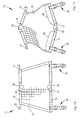
- Fig. 1
- die zwischen dem Dach eines Kraftfahrzeuges und der Rücksitzlehne aufgespannte Trenneinrichtung in einer perspektivischen Darstellung mit teilweise aufgebrochener Fahrzeugkarosserie;
- Fig. 2
- das Mittenscharnier der Streben der Trenneinrichtung nach Fig. 1 in einem Schnitt parallel zur Scharnierachse;
- Fig. 3
- das Mittenscharnier nach Fig. 2 in einer schematisierten Explosionsdarstellung;
- Fig. 4 und 5
- die Scharnierlaschen des Scharniers in einer Draufsicht, bzw. in einem Schnitt längs der Linie IV-IV nach Fig. 4;
- Fig. 6
- die Feder zum Vorspannen des Verriegelungsbolzens des Scharniers nach Fig. 2;
- Fig. 7
- das scharnierseitige Ende eines Strebenabschnitts der Trenneinrichtung nach Fig. 1 in einer abgebrochenen perspektivischen Darstellung;
- Fig. 8
- die montierte Anordnung aus der Strebe und der entsprechenden Scharnierlasche;
- Fig. 9
- eines der energieverzehrenden Elemente der oberen Strebe der Trenneinrichtung nach Fig. 1 und
- Fig. 10
und 11 - unterschiedliche Stellungen der Trenneinrichtung nach Fig. 1 bei der Handhabung
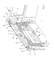
- Fig. 1
- the separating device stretched between the roof of a motor vehicle and the rear seat back in a perspective view with the vehicle body partially broken away;
- Fig. 2
- the central hinge of the struts of the separating device according to Figure 1 in a section parallel to the hinge axis.
- Fig. 3
- the center hinge of Figure 2 in a schematic exploded view.
- 4 and 5
- the hinge tabs of the hinge in a plan view, or in a section along the line IV-IV of Fig. 4;
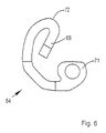
- Fig. 6
- the spring for biasing the locking bolt of the hinge according to Fig. 2;
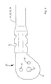
- Fig. 7
- the hinge-side end of a strut section of the separating device according to Figure 1 in a broken perspective view.
- Fig. 8
- the assembled arrangement of the strut and the corresponding hinge bracket;
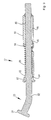
- Fig. 9
- one of the energy-consuming elements of the upper strut of the separating device according to FIGS. 1 and
- 10 and 11
- different positions of the separator according to Fig. 1 in handling
Fig. 1 zeigt in aufgebrochener Darstellung einen Heckbereich
1 eines Kombi-PKW. Der Heckbereich 1 ist perspektivisch
etwa aus der Sicht des weggebrochenen, linken seitlichen
Heckfensters dargestellt. Er weist ein Dach 2 auf, das
seitlich von zwei C-Säulen 3 getragen wird. Vor der C-Säule
3 liegt unterhalb des Daches 2 und oberhalb einer Seitenwand
4 ein hinteres Seitenfenster 5, während hinter der C-Säule
3 ein weiteres hinteres Seitenfenster 6 angeordnet
ist. Die Anordnung der Seitenfenster 5, 6 ist auf der linken
Seite des Heckbereiches 1 spiegelbildlich zu denken.Fig. 1 shows a broken area a rear area
1 of a station wagon. The rear area 1 is perspective
about from the perspective of the broken-away left side
Rear window shown. It has a
Nach unten wird der Heckbereich 1 von einer im Wesentlichen ebenen Ladefläche 7 abgeschlossen.Down the rear area 1 is essentially one flat loading area 7 completed.
Zwischen den beiden hinteren Seitenfenstern 5 befindet
sich auf der Höhe der C-Säule eine Rücksitzbank 8, deren
Rücksitzlehne 9 mit einer Rückseite 11 etwa zwischen den
beiden C-Säulen 3 steht.Is located between the two rear side windows 5
at the level of the C-pillar a back seat 8, whose
Back seat back 9 with a rear 11 approximately between the
two C-
Zwischen der Unterkante des Daches 2 und der Oberkante
der Rücksitzlehne 9 befindet sich eine Öffnung 12, über die
ein vor der Rücksitzlehne 9 befindlicher Fahrgastraum mit
dem dahinter befindlichen Laderaum des Heckbereiches 1 in
Verbindung steht. Between the lower edge of the
Um zu verhindern, dass bei einem Crash Gegenstände aus
dem Heckbereich 1 in den Fahrgastraum geschleudert werden,
wird die Öffnung 12 durch eine Trenneinrichtung 13 verschlossen.To prevent objects from falling out
the rear area 1 are thrown into the passenger compartment,
the
Zu der Trenneinrichtung 13 gehört ein Flächengebilde
in Gestalt eines trapezförmig zugeschnittenen Trenn-Netzes
14, das seitlich von Einfassbändern 15 eingefasst ist und
dessen obere und dessen untere Kante jeweils von einer angenähten
und angeschweißten schlauchförmigen Schlaufe 16,
17 gebildet ist. Durch die Schlaufe 16 führt eine Strebe
19, die mit der Schlaufe 16 zusätzlich bspw. mit Hilfe von
nicht gezeigten Nieten verbunden ist, um zu verhindern,
dass sich die Strebe 19 in der Schlaufe 16 drehen oder in
Längsrichtung der Strebe 19 verschieben kann.A sheet is part of the separating
In ähnlicher Weise ist die Verbindung zwischen der
unteren Strebe 21 und der unteren Schlaufe 17 ausgeführt,
d.h. auch die Strebe 21 kann sich in der Schlaufe 17 weder
drehen noch verschieben.Similarly, the connection between the
Die Strebe 19 ist rohrförmig ausgeführt und sie enthält
in ihren nach außen zeigenden Enden energieverzehrende
Elemente 22, deren Aufbau im Einzelnen in Fig. 9 gezeigt
ist.The
Aus dem energieverzehrenden Element 22 stehen Befestigungsglieder
23 vor, die endseitig pilzförmige Köpfe 24
tragen. Mit diesen pilzförmigen Köpfen 24 sind die Befestigungsglieder
23 in karosseriefesten T-Nuten 25 aufgenommen.Fastening members are made of the energy-consuming
Die Unterkante mit der Strebe 21 wird mit Hilfe von
zwei Zugbändern 26 und nicht weiter erkennbaren Haken an
Ösen 27 befestigt, die an der Rückseite 11 der Rücklehne 9
angebracht sind. Die Zugbänder 26 sind begrenzt dehnbar.The lower edge with the
Gemäß der Erfindung sind die beiden Streben 19 und 21
in ihrer wirksamen Länge verkürzbar. Zu diesem Zweck enthält
sowohl die Strebe 19 als auch die Strebe 21 ein mittleres
Scharnier 30, das bspw. die Strebe 19 in einen linken
Strebenabschnitt 31 und einen rechten Strebenabschnitt 32
aufteilt. In ähnlicher Weise wird die Strebe 21 durch das
Scharnier 30 in einen linken und einen rechten Strebenabschnitt
33 und 34 aufgeteilt.According to the invention, the two
Der Aufbau des Scharniers 30 und die Verbindung mit
den rohrförmigen Strebenabschnitten 31... 34 wird nachstehend
anhand der Fig. 2 bis 8 erläutert.The structure of the
Zu dem Scharnier 30 gehören zwei identische Scharnierlaschen
35a und 35b, die als Blechbiege- und -stanzteile
ausgeführt sind sowie zwei schalenförmige Scharnierdeckel
36a und 36b, die nahezu identisch sind.The
Die Scharnierlasche 35a setzt sich aus einem plattenförmigen
Laschenabschnitt 37 mit zwei zueinander parallelen
Flachseiten 38 und 39 und einem einstückig davon ausgehenden
Fortsatz 41 zusammen. Die Dicke des Fortsatzes 41 ist
gleich der Dicke des Laschenabschnittes 37, und auch dieser
wird von einer im Wesentlichen planen Flachseite 42 und
einer dazu parallelen Flachseite 43 begrenzt. Der Laschenabschnitt
37 hat in der Draufsicht im weitesten Sinne eine
etwa dreieckförmige Gestalt mit stark verrundeten Ecken. Am
Übergang von dem ebenen Laschenabschnitt 37 zu dem Fortsatz
41 ist die Scharnierlasche 35a mit einer Abkröpfung 44 versehen.
Die Abkröpfung 44 hat eine solche Tiefe, dass die
Mittelebene zwischen den Flachseiten 42 und 43 des Fortsatzes
41 mit der Flachseite 37 bündig ist.The
Im Übrigen verläuft der Fortsatz 41 parallel zu einer
Ebene die bspw. durch die Flachseite 37 definiert ist.In addition, the
Um den Übergang zwischen dem Laschenabschnitt 37 zu
dem Fortsatz 41 auszusteifen, ist eine längsovale Sicke 45
vorgesehen, die sich durch die Abkröpfung 44 hindurch
erstreckt und von der sich ein Ende in dem Laschenabschnitt
37 und der andere in dem Fortsatz 41 befindet. Die Sicke 45
ist so gestaltet, dass sie sich aus den Flachseiten 39 und
43 erhebt, d.h. auf jener Seite konkav ist, an der der
Fortsatz 41 zufolge der Abkröpfung 44 gegenüber der Flachseite
38 erhöht ist. Diese Ausgestaltung ist am besten aus
Fig. 5 zu erkennen.To the transition between the
Zufolge der Abkröpfung können die beiden identischen
Scharnierlaschen 35a und 35b mit ihren Flachseiten 38 zur
Anlage gebracht werden, während die zugehörigen Fortsätze
41 sich dann in einer gemeinsamen Ebene befinden, d.h. sie
weisen gegenüber der Trennfläche, an der die beiden Flachseiten
38 aufeinander liegen, jeweils denselben Versatz in
entgegengesetzter Richtung auf.As a result of the offset, the two can be
Der Fortsatz 41 enthält in seinen gegenüberbefindlichen
Rändern insgesamt vier etwa sägezahnförmig ausgestaltete
Kerben oder Einschnitte 46, die in einer später noch
beschriebenen Weise der Befestigung des betreffenden Strebenabschnitts
31...34 dient.The
In dem Laschenabschnitt 37 sind zwei zylindrische Bohrungen
47 und 48, sowie eine Gewindebohrung 49 enthalten.
Die Bohrung 47 ist, wie die Fig. erkennen lassen, gegenüber
dem Fortsatz 41 deutlich versetzt. Sie bildet bei montiertem
Scharnier 30, wie Fig. 2 zeigt, die Scharnierbohrung,
durch die ein Scharnierbolzen 51 hindurch führt, der auf
beiden Seiten mit einem Schließ- bzw. einem Nietkopf versehen
ist.In the
Im montierten Zustand nach Fig. 2 liegen die beiden
Scharnierlaschen 35a und 35b mit ihren Flachseiten 38 aufeinander
und sind im Bereich der Scharnierbohrung 37 durch
den Scharnierbolzen 51 drehbar aber ansonsten starr miteinander
verbunden sind. Aufgrund des Scharnierbolzens 41 können
die beiden Laschen 35a, 35b nur eine Drehbewegung in
einer Ebene ausführen, die durch die Flachseite 38 definiert
ist.2 are in the assembled
Die anderen beiden Flachseiten 39 zeigen bei vernietetem
Scharnier 30 nach außen.The other two
Die Scharnierdeckel 36a und 36b sind schalenförmig und
bestehen aus einem im Wesentlichen ebenen Boden 52, an den
eine endlos umlaufende Seitenwand 53 angeformt ist. Die
Kontur der Seitenwand 53 folgt weitgehend der Außenkontur
des Laschenabschnittes 37, wobei die Seitenwand 53 im Bereich
der Abkröpfung 44 eine gerade Wand 54 bildet.The hinge covers 36a and 36b are bowl-shaped and
consist of a substantially flat bottom 52 to which
an endless
Die Seitenwand 53 ist an ihrer freien, von dem Boden
52 abliegenden Kante, mit einem Rücksprung 55 versehen mit
dem sie,.wie Fig. 2 zeigt, die Außenseite des Laschenabschnittes
37 umgreift. Die gerade Seitenwand 54 folgt mit
ihrer von dem Boden 52 abliegenden freien Kante der Kontur
der Flachseite 43 bzw. 39 im Bereich der Abkröpfung 44. Im
montierten Zustand ist damit der Laschenabschnitt 37 von
dem Deckel 36 verschlossen, während der Fortsatz 41 unter
der Wand 54 hervorsteht.The
An dem Boden 52 ist ein zylindrischer Fortsatz 56 angeformt,
dessen axiale Länge so bemessen ist, dass er auf
der Flachseite 39 aufliegt, wenn der Rücksprung 55 ebenfalls
an die Flachseite 39 anstößt. In dem Fortsatz 56 befindet
sich eine Durchgangsbohrung 57, die auf der Außenseite
des Deckels 36 in eine Kegelsenkung 58 übergeht.
Durch die so erhaltene Kegelbohrung führt eine Senkschraube
59, die in die Gewindebohrung 49 eingedreht ist. Auf diese
Weise wird der Deckel 36 an der betreffenden Lasche 35a
bzw. 35b fixiert.A
Der Deckel 36b enthält zusätzlich zu der Bohrung 57
eine weitere zylindrische Bohrung 61, die an der Innenseite
des Deckels 52 von einem kurzen zylindrischen Kragen 62
umgeben ist. Die Bohrung 61 fluchtet bei montiertem Deckel
36b mit der zylindrischen Bohrung 48. Diese wiederum befindet
sich, wie die Fig. 3 erkennen lässt, oberhalb der
Scharnierbohrung 47 und zwar an einer solchen Stelle, dass
die beiden Fortsätze 41 in Verlängerung zueinander verlaufen,
wenn die Bohrungen 48, wie Fig. 2 erkennen lassen,
miteinander zur Deckung gebracht sind.The
Die Bohrungen 48 in den beiden Scharnierlaschen 35a
und 35b dienen der Aufnahme eines zylindrischen Verriegelungsbolzens
53, der in den Bohrungen 48 frei verschieblich
ist. Mit Hilfe einer Blattfeder 64, die im Einzelnen in
Fig. 6 gezeigt ist, wird der Verriegelungsbolzen 63 in
Richtung auf die Bohrung 61 zu vorgespannt. Die Länge des
Verriegelungsbolzens 63 ist etwa gleich der doppelten Stärke
des Laschenabschnittes 37. The
Um den Scharnierbolzen 63 in die entriegelte Lage zu
bringen, ist ein Entriegelungsknopf 65 vorhanden, der sich
aus einem zylindrischen Schaft 66 und einem Betätigungskopf
67 zusammensetzt. Mit dem zylindrischen Schaft 66 ist der
Entriegelungsknopf in der zylindrischen Bohrung 41 längsverschieblich
geführt und wird durch eine Krallenfederscheibe
68, die auf dem Schaft 66 sitzt, gegen Herausfallen
gesichert.To the
Die Blattfeder 64 liegt auf der nach außen zeigenden
Seite 39 auf. Sie ist in Fig. 6 in der Draufsicht gezeigt
und weist einen gekrümmten Verlauf mit einem Federarm 69
auf, der gegen den Verriegelungsbolzen 63 drückt. Am gegenüberliegenden
Ende geht die Blattfeder 64 in ein Befestigungsauge
71 über, das bei der Montage auf der Gewindebohrung
49 zu liegen kommt und zwischen dem Laschenabschnitt
37 und dem Fortsatz 56 des betreffenden Deckels 36 eingeklemmt
wird.The
Die Außenkontur der Blattfeder 64 folgt im Wesentlichen
der Innenkontur des Deckels 36, so dass sich die
Blattfeder 64 auf der Flachseite 39 nicht verdrehen kann.
Ihr stark geknickter Bereich 72 stößt dazu an der Innenseite
der geraden Seitenwand 54 an. Auf diese Weise wird sichergestellt,
dass das freie Ende 69 immer auf den Verriegelungsbolzen
63 einwirken kann.The outer contour of the
Die Montage und der Aufbau des Scharniers 30 ist wie
folgt:
Sodann wird auf jene Scharnierlasche 35, die in Fig. 2
auf der linken Seite dargestellt ist, die Blattfeder 64
aufgelegt und zwar in einer Stellung, in der das Auge 71
mit der Gewindebohrung 49 deckungsgleich ist, während der
freie Arm 69 die Bohrung 48 überdeckt. Anschließend wird
der betreffende Deckel 36 mit Hilfe einer entsprechenden
Schraube 59 aufgeschraubt, wobei gleichzeitig die Blattfeder
64 lagerichtig auf der betreffenden Scharnierlasche
35 fixiert wird. Anschließend werden die beiden Scharnierlaschen
35a und 35b in eine Stellung gebracht, in der die
Bohrungen 48 miteinander fluchten, damit der Verriegelungsbolzen
63 in diese eingesteckt werden kann. Abschließend
wird der andere Deckel 36b in ähnlicher Weise auf der noch
freiliegenden Scharnierlasche 35b befestigt. Zuvor wurde
noch der Entriegelungsknopf 65 eingesteckt und mit der
Krallenfederscheibe 68 gesichert.Then the
Durch Eindrücken des Entriegelungsknopfes 65 wird der
Verriegelungsbolzen 63 aus der Bohrung 48 der Scharnierlasche
35b weggedrückt, wobei gleichzeitig der Schaft 66 in
die Bohrung 48 vordringt. Sobald der Entriegelungsknopf 65
vollständig eingedrückt ist, bis sein Betätigungsknopf 67
auf dem Anschlag auf dem Deckel 36 anliegt, ist der Verriegelungsbolzen
63 gegen die Wirkung der Blattfeder 64 weit
genug zurückgedrückt, bis er nicht mehr in die Bohrung 48
der Scharnierlasche 35b hineinragt. Die beiden Scharnierlaschen
35a und 35b können nun gegeneinander gedreht werden,
wobei nach einer kurzen Verschwenkung der Entriegelungsknopf
65 losgelassen werden kann, ohne dass es zu einer
erneuten Verriegelung kommt. Nach einem kurzen Schwenkweg
steht dem Verriegelungsbolzen 63, der sich nun nur noch in
der Bohrung 48 der Scharnierlasche 35 befindet, die Flachseite
38 der anderen Scharnierlasche 35 gegenüber. Damit
ist jederzeit eine Verschwenkung der beiden Scharnierlaschen
35a und 35b gegeneinander möglich.By pushing the
Sobald die Scharnierlaschen wieder in eine Stellung
zurückgeschwenkt werden, in der die beiden Fortsätze 41
zueinander gestreckt verlaufen, kommen die beiden Verriegelungsbohrungen
48 wieder zueinander zur Deckung und die
Blattfeder 64 kann den Verriegelungsbolzen 63 in die Lage
nach Fig. 2 zurückdrücken um das Scharnier 30 in der gestreckten
Stellung zu blockieren.Once the hinge tabs are back in position
be pivoted back, in which the two
An einem Herausfallen in der entgegengesetzten Richtung
wird der Verriegelungsbolzen 63 durch den Entriegelungsknopf
65 gehindert, indem sich dessen Krallenfederscheibe
68 an der freien Stirnseite des Kragens 62 anlegt.Falling out in the opposite direction
the locking
Jeder der Strebenabschnitte 31...34 besteht aus einem
entsprechend langen Stahlrohrabschnitt mit rundem
Querschnitt. An jenem Ende, an dem später die Verbindung
zwischen dem Scharnier 30 und dem Strebenabschnitt 31...34
hergestellt werden soll, wird das zunächst zylindrische
Rohr über die Länge eines Bereiches 73, wie aus Fig. 7 ersichtlich
ist, umgeformt, damit ein längsovaler Querschnitt
entsteht mit einer Ausbuchtung 74 zur Aufnahme der Sicke
45. Der Querschnitt des Strebenabschnittes 31...34 entspricht
somit im Wesentlichen dem Querschnitt des betreffenden
Fortsatzes 41 in einer Schnittebene rechtwinklig zu
seiner Längserstreckung, und zwar über eine Länge, die etwas
größer ist als die Länge des Fortsatzes 41.Each of the
Die Verbindung mit dem Scharnier 30 geschieht, wie
dies Fig. 8 erkennen lässt, indem die betreffende Strebe
31...34 mit ihrem Ende 73 voraus auf den entsprechenden
Fortsatz 41 der Scharnierlasche 35 aufgesteckt wird. Sodann
werden in die Strebe 31...34 Kerben 75 eingedrückt, womit
das Wandmaterial der Strebe 31...34 die sägezahnförmigen
Kerben 46 eingeprägt wird. Hierdurch entsteht eine spielfreie
und zugfeste Verbindung zwischen der Scharnierleiste
35 und der betreffenden Strebe 31...34. Die Verbindung mit
den Strebenabschnitten 31...34 kann vor oder nach der Montage
des Scharniers 30 erfolgen.The connection with the
Der Vollständigkeit halber seien noch kurz die energieverzehrenden
Elemente 22 erläutert, deren Funktionsweise
im Einzelnen in der DE-A 43 36 380 beschrieben ist.For the sake of completeness, the energy-consuming ones are
Zu dem energieverzehrenden Element 22 gehört eine
rohrförmige Kunststoffhülse 81, in der längsverschieblich
ein zylindrischer Schaft 82 des Verankerungselementes 23
steckt. An den Schaft 82 sind mehrere nach außen wegstehende
Laschen 83, 84 und 85 angequetscht, die in entsprechenden
Längsnuten 86 und 87 laufen, die in der Seitenwand einer
zylindrischen Bohrung 88 der Hülse 81 ausgebildet sind.
Auf diese Weise ist der Schaft 32 in der Hülse 81 unverdrehbar.
Eine Schraubendruckfeder 89, die sich in der Bohrung
88 befindet, stützt sich einerseits an den beiden miteinander
fluchtenden Laschen 83 und 84 ab und andererseits
an einem Ring 91, der aus einem festen Material besteht und
mit Hilfe von Sicken in den beiden Strebenabschnitten 31
und 32 festgelegt ist.One belongs to the energy-consuming
Durch die Druckfeder 89 wird das Verankerungsglied 23
nach außen in die vorgeschobene Stellung gedrückt, in der
die Lasche 85 an der Rückseite des Rings 91 anliegt.The anchoring
Im Bereich der unteren Schlaufe 17 sind an dem Trennnetz
14 noch zwei Folienzuschnitte 95 und 96 angenäht, deren
freie Ränder 97 bzw. 98 jeweils mit einem Teil eines
Reißverschlusses versehen sind. Die beiden Zuschnitte 95
und 96 sind Seitenwände einer Tasche, die dem Verstauen der
nicht gebrauchten Trenneinrichtung dient.In the area of the
Zur Erläuterung der Handhabung der erfindungsgemäßen
Trenneinrichtung 13 sei angenommen, dass sie in dem Fahrzeug
installiert ist, wie dies Fig. 1 zeigt. Die beiden
Scharniere 30 stehen in jener Stellung, in der die Fortsätze
41 und damit die Strebenabschnitte 31...34 sich jeweils
in der Verlängerung des betreffend anderen Strebenabschnitts
41...34 befinden, wie dies die Figur erkennen
lässt. Wie es sich aus der obigen Beschreibung des Scharniers
30 ergibt, ist in dieser Schwenklage der Verriegelungsbolzen
63 eingerastet und sperrt das Scharnier 30 gegen
Knicken.To explain the handling of the
In der Gebrauchsstellung ist die Achse des Scharnierbolzens
51 sowohl des oberen Scharniers 30 als auch des
unteren Scharniers 30 parallel zu der Fahrzeuglängsachse
ausgerichtet.The axis of the hinge pin is in the
Wenn in der Gebrauchslage wegen eines Crashes ein Gegenstand
aus dem Laderaum gegen das Trenn-Netz 14 geschleudert
wird, wird er von dem Trenn-Netz 14 zurückgehalten.
Dabei werden die obere und die untere Strebe 19, 21 auf
Knick beansprucht, wobei die maximale Knickkraft im Bereich
der Gelenke 30 auftritt. Da dort die beiden Scharnierlaschen
35 über die Laschenabschnitte 37 flächig aufeinander
liegen, ist das Scharnier 30 in der Lage verhältnismäßig
große Knickkräfte auszuhalten. Darüber hinaus ist der Übergang
zwischen dem Laschenabschnitt 37 und dem Fortsatz 41
durch die Sicke 45 verstärkt, womit sich insgesamt auch in
diesem Bereich eine Festigkeit ergibt, die der Festigkeit
eines durchgehenden Stahlrohrs entspricht, das die Abmessungen
der Strebenabschnitte 31...34 aufweist.If an object in the position of use due to a crash
hurled out of the hold against the
Wenn die Trenneinrichtung 13 nicht benötigt wird, werden
zur Entnahme zunächst die unteren Zugbänder 26 mit ihren
Haken aus den Ösen 27 ausgehängt. Sodann wird die obere
Strebe mit ihren Verankerungsgliedern 23 aus den T-Nuten 25
herausgezogen. Die Trenneinrichtung 13 kann nunmehr vollständig
aus dem Fahrzeug entnommen werden.If the
Nach der Entnahme aus dem Fahrzeug ergibt sich ein
Bild gemäß Fig. 10. Der Benutzer kann nun bspw. zunächst
das Scharnier 30 der unteren Strebe 21 entriegeln, indem
der Entriegelungsknopf 65 eingedrückt wird. Dadurch wird
das Scharnier 30 freigegeben und kann, wie oben ausführlich
erläutert ist, eingefaltet werden. Den Beginn der Einfaltung
zeigt Fig. 11.After removal from the vehicle, a
10. The user can now, for example
unlock the
Sodann wird dieser Vorgang mit dem Entriegelungsknopf
65 des Scharniers 30 an der oberen Strebe 19 wiederholt.
Allerdings wird die obere Strebe 19 vollständig zusammengefaltet,
soweit bis deren beide Strebenabschnitte 31 und 32
im Bereich ihrer von dem Scharnier 30 abliegenden Enden
bspw. bei den pilzförmigen Köpfen 24 zusammenstoßen. Je
nach den Abmessungen des Trenn-Netzes 14 folgen die unteren
beiden Strebenabschnitte 33 und 34 dieser Faltbewegung.Then this process with the
Da die Achse des Scharniers 30 auf der aufgespannten
Fläche des Trennnetzes 14 senkrecht steht und die Strebe 19
im Übrigen drehfest mit dem Netz 14 verbunden ist, wird zum
vollständigen Zusammenlegen die Strebe um etwa 90° gedreht,
so weit bis die Achse des Scharniers 30 bei der Handhabung
parallel zu dem lose herunterhängenden Trenn-Netz 14 liegt.
In dieser Stellung wird das Zusammenfalten der Strebe 19
durch das Trenn-Netz 14 nicht behindert.Since the axis of the
Im zusammengeklappten Zustand haben die beiden Strebenabschnitte
31 und 32 in der unmittelbaren Nähe des
Scharniers einen Abstand, der größer ist als es dem Durchmesser
auch eines kräftigen Fingers entspricht, damit nicht
die Gefahr der Quetschung entsteht. Dieser Abstand wird
erreicht, weil die Scharnierbohrung 47 gegenüber den Fortsätzen
41 seitlich versetzt ist.When folded, the two strut sections have
31 and 32 in the immediate vicinity of the
Hinge a distance that is greater than its diameter
also corresponds to a strong finger, so not
there is a risk of being crushed. This distance will
reached because the hinge bore 47 relative to the
Falls noch nicht geschehen, wird sodann auch die untere
Strebe 21 in ähnlicher Weise vollständig zusammengefaltet.
Sodann wird von der oberen zusammengefalteten Strebe
19 her das Trenn-Netz 14 auf die zusammengeklappte Strebe
19 aufgewickelt, bis der entstandene Wickel an der zusammengefalteten
Strebe 21 ankommt.If not already done, the lower one will also be
Aufgrund des Einfaltens der unteren Strebe 21 kommen
die beiden Zuschnitte 95 und 96 in eine Lage, in der sie im
Wesentlichen zueinander parallel verlaufen, und zwar auf
der Außenseite des erhaltenen Wickels aus dem Trenn-Netz 14
und zu beiden Seiten des erhaltenen Wickels. Nunmehr kann
der Reißverschluss, der an der freien Kante 96 bzw. 97 befestigt
ist, geschlossen werden, womit der Wickel sicher in
der so entstandenen Tasche aufbewahrt ist. Ein Auseinanderklappen
wird durch die mit dem Reißverschluss verbundenen
Zuschnitte 95 und 96 verhindert, die die Seitenwände der
Tasche bilden. Die erhaltene Tasche ist keine vollständige
Tasche, denn ihr fehlt der Boden. Dennoch ist sie in der
Lage den Wickel weitgehend gegen Aufklappen zu sichern.Due to the folding of the
Die effektive Länge der Streben 19 und 21 ist durch
das Falten auf die Hälfte reduziert worden, womit der entstandene
Wickel eine Länge hat, die deutlich kürzer ist als
es der Breite des aufgespannten Sicherheitsnetzes 14 entspricht.
Das zusammengefaltet und aufgewickelte Trenn-Netz
14 lässt sich nunmehr ohne Weiteres innerhalb des
Kraftfahrzeugs unterbringen.The effective length of the
Um eine Beschädigung des Trenn-Netzes 14 im Bereich
der Scharniere 30 zu verhindern, kann das Trenn-Netz 14,
wie in Fig. 1 gezeigt, in der Umgebung der Scharniere 30
mit einer Aussparung 98 versehen werden.To damage the
Abweichend von der dargestellten Form besteht auch die
Möglichkeit zusätzlich zu den beiden an den Endschlaufen 16
und 17 vorgesehenen Streben 19 und 21 eine dritte Strebe zu
verwenden, die etwa auf der Mitte verläuft und im Übrigen
genauso gestaltet ist wie die Streben 19 und 21. Diese zusätzliche
Strebe kann mit Anschlägen im Kraftfahrzeug zusammenwirken,
um zusätzlich zur Festigkeit der Trenneinrichtung
13 beizutragen.Deviating from the form shown, there is also
Possibility in addition to the two at the
Zu einer Trenneinrichtung gehört ein Trenn-Netz oder Trenngitter aus einem flexiblen Material. An zwei zueinander parallel verlaufenden Kanten des Trenn-Netzes ist jeweils eine Versteifungsstrebe vorgesehen. Eine der beiden Versteifungsstreben dient der Verankerung des Trenn-Netzes unterhalb des Fahrzeugsdaches, während die andere Versteifungsstrebe im Abstand zum Dachhimmel, bspw. an der Rücklehne oder am Boden des Laderaums verankert wird. Die beiden Versteifungsstreben enthalten jeweils ein Scharnier. Auf diese Weise kann die Trenneinrichtung der Breite nach zusammengefaltet und anschließend aufgerollt werden. Eine Verstaueinrichtung in Gestalt einer an der Trenneinrichtung vorgesehenen Tasche dient der Sicherung des gefalteten Trenn-Netzes in der verstauten Stellung.A separation network or belongs to a separation device Partition grid made of a flexible material. At two to each other parallel edges of the separation network each provided a stiffening strut. One of the two Stiffening struts serve to anchor the separation net below the vehicle roof, while the other stiffening strut at a distance from the headlining, for example on the backrest or anchored to the floor of the cargo hold. The two Stiffening struts each contain a hinge. In this way, the separator can be wide folded up and then rolled up. A Storage device in the form of a on the separating device provided pocket serves to secure the folded Separating net in the stowed position.
Claims (41)
- Removable separating device (13), which is provided for the purpose of separating a luggage area from a passenger compartment in a motor vehicle,
with an upper strut (19), which is to be detachably anchored in the motor vehicle and the effective length of which may be shortened by more than at least 30% of its maximum length,
with a lower strut (21), which is to be detachably anchored in the motor vehicle and the effective length of which may be shortened by more than at least 30% of its maximum length, and
with a flexible, essentially non-stretch fabric (14), which is fastened to the upper and the lower strut (19, 21). - Separating device according to Claim 1, characterised in that the lower and the upper strut (19, 21) are capable of being folded at least once to shorten their effective length.
- Separating device according to Claim 1, characterised in that to shorten their effective length, the lower and the upper strut (19, 21) each contain at least one hinge (30) with a hinge axis (51), which divides the respective strut (19, 21) into strut sections (31...34).
- Separating device according to Claim 3, characterised in that in the case of one hinge (30) per strut (19, 21), the two strut sections (31...34) of each strut (19, 21) are of equal length.
- Separating device according to Claim 3, characterised in that the hinges (30) are aligned to one another such that when the separating device (13) is opened out, the two hinges (30) lie on a straight line, which stands perpendicular on the two parallel struts (19, 21).
- Separating device according to Claim 3, characterised in that when the separating device (13) is opened out, the hinge axes (51) are preferably aligned horizontally.
- Separating device according to Claim 3, characterised in that the strut sections (31...34) adjacent to the respective hinge (30) are displaced radially with respect to the hinge axis (51) in such a way that when a strut (19, 21) is folded, its strut sections (31...34) are at least to be brought into a position parallel to one another.
- Separating device according to Claim 3, characterised in that the strut sections (31...34) adjacent to the respective hinge (30) are displaced radially with respect to the hinge axis (51) in such a way that when a strut (19, 21) is folded, its strut sections (31...34) next to the hinge (30) are spaced from one another when the ends of the strut sections (31...34) remote from the hinge (30) abut against one another.
- Separating device according to Claim 8, characterised in that the spacing in the vicinity of the hinge (30) amounts to at least 1.5 cm.
- Separating device according to Claim 3, characterised in that the hinge (30) is a simple hinge with only one hinge axis (51).
- Separating device according to Claim 3, characterised in that the hinge (30) has two hinge plates (35), which are undetachably connected to one another by a hinge pin (51).
- Separating device according to Claim 11, characterised in that each hinge plate (35) bears an extension (41), to which the respective strut section (31...34) is fastened.
- Separating device according to Claim 11, characterised in that in one position of the hinge (30), in which the extensions (41) of the hinge plates (35) lie on a straight line, the hinge axis (51) is laterally displaced relative to the extensions (41), i.e. as measured in a plane, on which the hinge axis (51) stands perpendicular.
- Separating device according to Claim 3, characterised in that the hinge (30) is lockable in at least one position.
- Separating device according to Claim 3, characterised in that the hinge (30) is detachably lockable by positive locking.
- Separating device according to Claim 15, characterised in that the position corresponds to the extended strut (19, 21).
- Separating device according to Claims 11 and 15, characterised in that the hinge plates (35) contain openings (48), which are flush with one another in the locking position, and that a bolt (63), which may be inserted into the openings (48), is provided for locking.
- Separating device according to Claim 17, characterised in that the bolt (63) is prestressed into the pushed forward position by means of a spring (64).
- Separating device according to Claim 17, characterised in that an operating member (65) disposed in the region of one of the hinge plates (35) is provided for the bolt (63).
- Separating device according to Claim 11, characterised in that the hinge axis (35) is provided with a crimp (45) extending into the extension (41) for reinforcement.
- Separating device according to Claim 11, characterised in that the extension (41) of each hinge plate (35) is bent at a right angle in such a manner that the extensions (41) run in a common plane, on which the hinge axis (51) stands perpendicular.
- Separating device according to Claim 11, characterised in that each hinge plate (35) contains recesses (46) in its edge.
- Separating device according to Claim 11, characterised in that a shell-like covering (36) is provided for each hinge plate (35).
- Separating device according to Claim 3, characterised in that the strut section (31...34) is tubular.
- Separating device according to Claim 3, characterised in that the strut section (31...34) is formed by a cylindrical tube, and that the tube is flattened in cross-section to receive the extension (41) of the respective hinge plate (35).
- Separating device according to Claim 3, characterised in that the strut section (31...34) is attached at one end to the extension (41) and is caulked with the extension (41) by displacing material of the strut section (31...34) into the recesses (46) on the edge side of the respective extension (41).
- Separating device according to Claim 3, characterised in that the strut sections (31...34) are made of an energy-absorbing, deformable material.
- Separating device according to Claim 1, characterised in that the fabric (14) is formed by a net.
- Separating device according to Claim 1, characterised in that the fabric (14) is made of a perforated foil.
- Separating device according to Claim 1, characterised in that the struts (19, 21) are fastened to the fabric (14) so that they cannot be relatively rotated.
- Separating device according to Claim 1, characterised in that the struts (19, 21) are fastened to the fabric (14) so that they cannot be displaced.
- Separating device according to Claim 3, characterised in that the fabric (14) contains a recess (98) in the region of the respective hinge (30).
- Separating device according to Claim 1, characterised in that it has a securing means (95, 96) to secure the separating device (13) in its stowed position.
- Separating device according to Claim 33, characterised in that the stowing means (95, 96) is formed by an undetachably fastened pocket, in which the separating device (13) is to be stowed.
- Separating device according to Claim 34, characterised in that two flexible pocket walls (95, 96) belong to the pocket, each of which extends along a strut section (33, 34) of one of the two struts (21) and each of which is fastened in the region of the respective strut section (33, 34).
- Separating device according to Claim 35, characterised in that each pocket wall (95, 96) carries one part of a zip fastener.
- Separating device according to Claim 1, characterised in that it has a third strut, which is connected to the fabric (14) and which is configured in the same manner as the other struts (19, 21).
- Separating device according to Claim 1, characterised in that the upper and/or the lower strut (19, 21) is provided with anchoring members (22) at the ends.
- Separating device according to Claim 38, characterised in that at least one of the anchoring members (22) is directed to be longitudinally displaceable with respect to the strut (19).
- Separating device according to Claim 1, characterised in that the lower strut (21) is provided with anchoring members (26) at a distance from its ends.
- Separating device according to Claim 40, characterised in that the anchoring members (26) are in the form of straps or cords.
Applications Claiming Priority (3)
| Application Number | Priority Date | Filing Date | Title |
|---|---|---|---|
| DE19944003A DE19944003C1 (en) | 1999-09-14 | 1999-09-14 | Foldable separator |
| DE19944003 | 1999-09-14 | ||
| PCT/DE2000/002949 WO2001019649A1 (en) | 1999-09-14 | 2000-08-30 | Foldable separating device |
Publications (2)
| Publication Number | Publication Date |
|---|---|
| EP1128992A1 EP1128992A1 (en) | 2001-09-05 |
| EP1128992B1 true EP1128992B1 (en) | 2004-09-22 |
Family
ID=7921977
Family Applications (1)
| Application Number | Title | Priority Date | Filing Date |
|---|---|---|---|
| EP00965793A Expired - Lifetime EP1128992B1 (en) | 1999-09-14 | 2000-08-30 | Foldable separating device |
Country Status (7)
| Country | Link |
|---|---|
| US (1) | US6595567B1 (en) |
| EP (1) | EP1128992B1 (en) |
| JP (1) | JP3623197B2 (en) |
| KR (1) | KR100584103B1 (en) |
| CN (1) | CN1144706C (en) |
| DE (2) | DE19944003C1 (en) |
| WO (1) | WO2001019649A1 (en) |
Cited By (2)
| Publication number | Priority date | Publication date | Assignee | Title |
|---|---|---|---|---|
| EP2052918A2 (en) | 2007-10-23 | 2009-04-29 | BOS GmbH & Co. KG | Collapsible dividing device for a motor vehicle |
| DE202008010747U1 (en) | 2008-08-08 | 2009-12-17 | Bos Gmbh & Co. Kg | Separating device for a vehicle interior of a motor vehicle |
Families Citing this family (34)
| Publication number | Priority date | Publication date | Assignee | Title |
|---|---|---|---|---|
| DE10054080C1 (en) * | 2000-10-31 | 2001-11-08 | Butz Peter Verwaltung | Safety net, for detachable fastening inside motor vehicle, has holder bar with locking element and release unit forming one integrated part |
| FR2835530B1 (en) | 2002-02-07 | 2004-04-09 | Inst Francais Du Petrole | INTEGRATED PROCESS FOR DESULFURIZING A CRACKING OR VAPOCRACKING OIL FROM HYDROCARBONS |
| US7048086B2 (en) * | 2002-08-26 | 2006-05-23 | Fujitsu Ten Limited | Vehicle protection apparatus at collision time |
| DE10242510B4 (en) * | 2002-09-12 | 2005-12-08 | Bos Gmbh & Co. Kg | Vehicle safety device, in particular separation network |
| US6962382B2 (en) * | 2003-05-23 | 2005-11-08 | David Scarlett | Barrier system |
| US7017965B2 (en) * | 2003-08-07 | 2006-03-28 | Bos Gmbh & Co. Kg | Motor-vehicle cargo net |
| DE202004007743U1 (en) * | 2004-05-11 | 2005-09-22 | Reum Protec Gmbh | Fastening device, in particular for a safety net arrangement for the protection of the passenger compartment of estate cars |
| DE202004008488U1 (en) * | 2004-05-25 | 2005-10-06 | Reum Protec Gmbh | Receiving device for a safety net |
| EP2177528B1 (en) | 2004-09-09 | 2011-12-07 | Teva Pharmaceutical Industries Ltd. | Process for the preparation of mixtures of trifluoroacetyl glatiramer acetate using purified hydrobromic acid |
| DE102004050546B4 (en) | 2004-10-16 | 2022-02-24 | Bayerische Motoren Werke Aktiengesellschaft | Retaining device for luggage in a vehicle |
| DE102006034635A1 (en) * | 2006-07-27 | 2008-01-31 | Dr.Ing.H.C. F. Porsche Ag | Protecting device for loading space of motor vehicle, has planar structure formed as spacer structure, where planar structure has reduced light transmission at horizontal protecting position and increased transmission in vertical position |
| US20080042462A1 (en) * | 2006-08-18 | 2008-02-21 | Kevin Scotton | Collapsible tubing device for automobile shade |
| EP2008877A1 (en) * | 2007-06-29 | 2008-12-31 | Ford Global Technologies, LLC | Soft cargo net |
| US20090057637A1 (en) * | 2007-08-30 | 2009-03-05 | Galla Paul V | Mounting Straps for Barriers |
| FR2932750B1 (en) | 2008-06-18 | 2012-05-11 | Cera | DEVICE FOR PROTECTING THE LUGGAGE OF A LUGGAGE COMPARTMENT OF A MOTOR VEHICLE |
| US8403615B1 (en) | 2008-08-20 | 2013-03-26 | Bruno Independent Living Aids, Inc. | Vehicle lift barrier |
| US20100244479A1 (en) * | 2009-03-25 | 2010-09-30 | International Truck Intellectual Property Company, Llc | Sliding bar assembly for use in cargo storage applications |
| CN102781726B (en) | 2011-03-02 | 2014-11-19 | 丰田自动车株式会社 | Component arrangement structure for roof side rail |
| KR20120114995A (en) * | 2011-04-08 | 2012-10-17 | 현대자동차주식회사 | Mounting structure of barrier net |
| EP2674333B1 (en) | 2012-06-11 | 2014-12-24 | Volvo Car Corporation | Foldable compartment divider for a vehicle |
| EP2703533A1 (en) | 2012-09-04 | 2014-03-05 | Volvo Car Corporation | A cargo net |
| US8714591B1 (en) * | 2013-02-06 | 2014-05-06 | Honda Motor Co., Ltd. | Vehicles, net assemblies, and clampers therefor |
| CN103437924B (en) * | 2013-08-15 | 2015-06-24 | 北京动力机械研究所 | Semi-flexible mechanism for redundant material protection |
| US9676339B2 (en) * | 2015-04-01 | 2017-06-13 | Ford Global Technologies, Llc | Versatile tonneau cover and storage system for a motor vehicle |
| US20160339846A1 (en) * | 2015-05-18 | 2016-11-24 | Ford Global Technologies, Llc | Integrated cargo cover |
| CN105730349B (en) * | 2016-03-08 | 2018-10-26 | 福建省汽车工业集团云度新能源汽车股份有限公司 | A kind of adjustable automobile luggage compartment baffling device |
| KR101795575B1 (en) * | 2016-07-28 | 2017-11-09 | 주식회사 서연이화 | Barrier Net For Vehicle |
| KR101795561B1 (en) * | 2016-07-28 | 2017-11-09 | 주식회사 서연이화 | Barrier Net For Vehicle |
| KR101795565B1 (en) * | 2016-07-29 | 2017-11-09 | 주식회사 서연이화 | Barrier Net For Vehicle |
| KR101795572B1 (en) * | 2016-07-29 | 2017-11-09 | 주식회사 서연이화 | Barrier Net For Vehicle |
| CN106627386B (en) * | 2016-09-28 | 2018-09-14 | 东莞市联洲知识产权运营管理有限公司 | A kind of boot of the new-energy automobile with separating device |
| DE102017206905A1 (en) | 2017-04-25 | 2018-10-25 | Bayerische Motoren Werke Aktiengesellschaft | Luggage compartment cover and separating device |
| US10202093B1 (en) | 2017-05-02 | 2019-02-12 | Brian Gethard | Barrier for an interior cab of vehicle |
| DE102018133161A1 (en) | 2018-12-20 | 2020-06-25 | Bayerische Motoren Werke Aktiengesellschaft | Restraint for luggage |
Family Cites Families (21)
| Publication number | Priority date | Publication date | Assignee | Title |
|---|---|---|---|---|
| US2565997A (en) * | 1949-08-09 | 1951-08-28 | Pittsburgh Steel Co | Load bracing frame |
| US2997331A (en) * | 1958-02-21 | 1961-08-22 | Donald F Kudner | Vehicle guard partition |
| US2982579A (en) * | 1958-03-19 | 1961-05-02 | Sidney D Greenwald | Adjustable and removable partitioning device for automobiles |
| US2998279A (en) * | 1959-01-09 | 1961-08-29 | Mateny Henry | Vehicle divider |
| US3044821A (en) * | 1959-10-27 | 1962-07-17 | Clarice B Wicker | Automobile safety barrier |
| US3049373A (en) * | 1961-04-03 | 1962-08-14 | William C Biggers | Safety guard attachment for the tailgate openings of station wagon vehicles |
| US3789439A (en) * | 1972-10-27 | 1974-02-05 | Cross River Prod Inc | Foldable and adjustable crib |
| US4281487A (en) * | 1979-08-06 | 1981-08-04 | Koller Karl S | Energy absorbing load carrying strut and method of providing such a strut capable of withstanding cyclical loads exceeding its yield strength |
| US4819300A (en) * | 1987-04-13 | 1989-04-11 | Hartwell Corporation | Strut assembly |
| US5215288A (en) | 1991-08-12 | 1993-06-01 | Roadway Express, Inc. | Load bar for a variably positioned bulkhead |
| USD348421S (en) * | 1993-02-22 | 1994-07-05 | Dexter Timothy J | Truck bed cargo restraining net |
| DE4336380C2 (en) | 1993-10-25 | 1995-08-10 | Baumeister & Ostler Gmbh Co | Safety net arrangement |
| US5427486A (en) * | 1994-03-17 | 1995-06-27 | Green; Gerald D. | Adjustable load securing device for vehicles |
| US5542151A (en) * | 1995-05-01 | 1996-08-06 | Century Products Company | Rotatable bending joint for collapsible playpen |
| DE19641794A1 (en) * | 1995-10-24 | 1997-04-30 | Volkswagen Ag | Holding device in transport vehicles to secures person, animal or goods during transit |
| DE19540934C2 (en) * | 1995-11-03 | 1998-10-29 | Opel Adam Ag | Partition for the variable separation of a loading area of a motor vehicle from a passenger compartment |
| US5730542A (en) * | 1997-05-14 | 1998-03-24 | Top Fortune Ltd. | Joint for a playen |
| DE19730801C1 (en) * | 1997-07-18 | 1999-03-25 | Baumeister & Ostler Gmbh Co | Safety retaining net for motor vehicle luggage |
| DE19731326C2 (en) * | 1997-07-22 | 2003-03-20 | Bayerische Motoren Werke Ag | Windbreak for a convertible |
| GB9721287D0 (en) * | 1997-10-07 | 1997-12-10 | Tomy Uk Ltd | Improvements in apparatus for use by babies and young children |
| US6371342B2 (en) * | 1998-07-21 | 2002-04-16 | Johnson Controls Technology Company | Cargo retention system |
-
1999
- 1999-09-14 DE DE19944003A patent/DE19944003C1/en not_active Expired - Fee Related
-
2000
- 2000-08-30 US US09/831,973 patent/US6595567B1/en not_active Expired - Lifetime
- 2000-08-30 JP JP2001523251A patent/JP3623197B2/en not_active Expired - Fee Related
- 2000-08-30 WO PCT/DE2000/002949 patent/WO2001019649A1/en active IP Right Grant
- 2000-08-30 DE DE50007886T patent/DE50007886D1/en not_active Expired - Lifetime
- 2000-08-30 EP EP00965793A patent/EP1128992B1/en not_active Expired - Lifetime
- 2000-08-30 CN CNB008019509A patent/CN1144706C/en not_active Expired - Fee Related
- 2000-08-30 KR KR1020017005950A patent/KR100584103B1/en not_active IP Right Cessation
Cited By (4)
| Publication number | Priority date | Publication date | Assignee | Title |
|---|---|---|---|---|
| EP2052918A2 (en) | 2007-10-23 | 2009-04-29 | BOS GmbH & Co. KG | Collapsible dividing device for a motor vehicle |
| DE102007052228A1 (en) | 2007-10-23 | 2009-06-10 | Bos Gmbh & Co. Kg | Collapsible separating device for a motor vehicle |
| EP2052918A3 (en) * | 2007-10-23 | 2010-03-17 | BOS GmbH & Co. KG | Collapsible dividing device for a motor vehicle |
| DE202008010747U1 (en) | 2008-08-08 | 2009-12-17 | Bos Gmbh & Co. Kg | Separating device for a vehicle interior of a motor vehicle |
Also Published As
| Publication number | Publication date |
|---|---|
| EP1128992A1 (en) | 2001-09-05 |
| KR20010089440A (en) | 2001-10-06 |
| WO2001019649A1 (en) | 2001-03-22 |
| DE50007886D1 (en) | 2004-10-28 |
| JP3623197B2 (en) | 2005-02-23 |
| US6595567B1 (en) | 2003-07-22 |
| JP2003509270A (en) | 2003-03-11 |
| DE19944003C1 (en) | 2001-03-22 |
| CN1321126A (en) | 2001-11-07 |
| CN1144706C (en) | 2004-04-07 |
| KR100584103B1 (en) | 2006-05-30 |
Similar Documents
| Publication | Publication Date | Title |
|---|---|---|
| EP1128992B1 (en) | Foldable separating device | |
| EP1060956B1 (en) | Separation device with adjustable retracting force | |
| EP0754594B1 (en) | Roller blind with high crash safety | |
| DE19546646A1 (en) | Backrest assembly for car seat | |
| DE102006018079B3 (en) | Cargo space for a motor vehicle with a protective device | |
| WO1988001950A1 (en) | Folding hood for cross-country vehicles | |
| EP1102691B1 (en) | Simple retaining net with retaining straps | |
| EP1435311B1 (en) | Loading space covering shelf comprising moveable corner pieces | |
| EP2330020B1 (en) | Side covering of a commercial vehicle structure | |
| EP1889740A1 (en) | Partition for a car | |
| DE19735463C1 (en) | Security net for luggage in motor vehicle | |
| EP3210808B1 (en) | Canvas roller and industrial vehicle with canvas cover | |
| DE60017403T2 (en) | BARRIER FOR MOTOR VEHICLES | |
| DE19650768C2 (en) | Safety net arrangement with simplified operation | |
| DE60201761T2 (en) | Load bearing device with at least two positions for motor vehicles | |
| DE2647104C3 (en) | Storage for a pivoting cover plate over the trunk of a motor vehicle | |
| DE2656249A1 (en) | IMPACT PROTECTION DEVICE FOR THE OCCUPANTS OF VEHICLES, IN PARTICULAR OF PERSONAL VEHICLES | |
| DE19730802C1 (en) | Safety net arrangement | |
| EP3862246A1 (en) | Protective device for arrangement in a space between two coupled vehicles | |
| DE19843044B4 (en) | Cargo restraint device for a motor vehicle | |
| EP0882612B1 (en) | Foldable tarpaulin for vehicle bodies and container | |
| DE3107001A1 (en) | Carrying device for attaching to the roof of a vehicle, in particular a passenger vehicle | |
| DE19709525C2 (en) | Safety net with a defined intermediate extension length | |
| DE19612019A1 (en) | Vehicle door impact buffers | |
| DE102021210817A1 (en) | AWNING |
Legal Events
| Date | Code | Title | Description |
|---|---|---|---|
| PUAI | Public reference made under article 153(3) epc to a published international application that has entered the european phase |
Free format text: ORIGINAL CODE: 0009012 |
|
| 17P | Request for examination filed |
Effective date: 20010601 |
|
| AK | Designated contracting states |
Kind code of ref document: A1 Designated state(s): AT BE CH CY DE DK ES FI FR GB GR IE IT LI LU MC NL PT SE |
|
| AX | Request for extension of the european patent |
Free format text: AL;LT;LV;MK;RO;SI |
|
| 17Q | First examination report despatched |
Effective date: 20030120 |
|
| GRAP | Despatch of communication of intention to grant a patent |
Free format text: ORIGINAL CODE: EPIDOSNIGR1 |
|
| RAP1 | Party data changed (applicant data changed or rights of an application transferred) |
Owner name: BOS GMBH & CO. KG |
|
| GRAS | Grant fee paid |
Free format text: ORIGINAL CODE: EPIDOSNIGR3 |
|
| GRAA | (expected) grant |
Free format text: ORIGINAL CODE: 0009210 |
|
| AK | Designated contracting states |
Kind code of ref document: B1 Designated state(s): DE FR GB IT |
|
| REG | Reference to a national code |
Ref country code: GB Ref legal event code: FG4D Free format text: NOT ENGLISH |
|
| GBT | Gb: translation of ep patent filed (gb section 77(6)(a)/1977) |
Effective date: 20040922 |
|
| REG | Reference to a national code |
Ref country code: IE Ref legal event code: FG4D Free format text: GERMAN |
|
| REF | Corresponds to: |
Ref document number: 50007886 Country of ref document: DE Date of ref document: 20041028 Kind code of ref document: P |
|
| LTIE | Lt: invalidation of european patent or patent extension |
Effective date: 20040922 |
|
| REG | Reference to a national code |
Ref country code: IE Ref legal event code: FD4D |
|
| ET | Fr: translation filed | ||
| PLBE | No opposition filed within time limit |
Free format text: ORIGINAL CODE: 0009261 |
|
| STAA | Information on the status of an ep patent application or granted ep patent |
Free format text: STATUS: NO OPPOSITION FILED WITHIN TIME LIMIT |
|
| 26N | No opposition filed |
Effective date: 20050623 |
|
| PGFP | Annual fee paid to national office [announced via postgrant information from national office to epo] |
Ref country code: GB Payment date: 20090827 Year of fee payment: 10 |
|
| PGFP | Annual fee paid to national office [announced via postgrant information from national office to epo] |
Ref country code: IT Payment date: 20090820 Year of fee payment: 10 |
|
| GBPC | Gb: european patent ceased through non-payment of renewal fee |
Effective date: 20100830 |
|
| PG25 | Lapsed in a contracting state [announced via postgrant information from national office to epo] |
Ref country code: IT Free format text: LAPSE BECAUSE OF NON-PAYMENT OF DUE FEES Effective date: 20100830 |
|
| PG25 | Lapsed in a contracting state [announced via postgrant information from national office to epo] |
Ref country code: GB Free format text: LAPSE BECAUSE OF NON-PAYMENT OF DUE FEES Effective date: 20100830 |
|
| REG | Reference to a national code |
Ref country code: FR Ref legal event code: PLFP Year of fee payment: 16 |
|
| PGFP | Annual fee paid to national office [announced via postgrant information from national office to epo] |
Ref country code: FR Payment date: 20150629 Year of fee payment: 16 |
|
| PGFP | Annual fee paid to national office [announced via postgrant information from national office to epo] |
Ref country code: DE Payment date: 20160831 Year of fee payment: 17 |
|
| REG | Reference to a national code |
Ref country code: FR Ref legal event code: ST Effective date: 20170428 |
|
| PG25 | Lapsed in a contracting state [announced via postgrant information from national office to epo] |
Ref country code: FR Free format text: LAPSE BECAUSE OF NON-PAYMENT OF DUE FEES Effective date: 20160831 |
|
| REG | Reference to a national code |
Ref country code: DE Ref legal event code: R119 Ref document number: 50007886 Country of ref document: DE |
|
| PG25 | Lapsed in a contracting state [announced via postgrant information from national office to epo] |
Ref country code: DE Free format text: LAPSE BECAUSE OF NON-PAYMENT OF DUE FEES Effective date: 20180301 |