EP1128070A2 - Verdichter - Google Patents
Verdichter Download PDFInfo
- Publication number
- EP1128070A2 EP1128070A2 EP01301654A EP01301654A EP1128070A2 EP 1128070 A2 EP1128070 A2 EP 1128070A2 EP 01301654 A EP01301654 A EP 01301654A EP 01301654 A EP01301654 A EP 01301654A EP 1128070 A2 EP1128070 A2 EP 1128070A2
- Authority
- EP
- European Patent Office
- Prior art keywords
- compressor
- recess
- outside diameter
- compressor wheel
- recessed portion
- Prior art date
- Legal status (The legal status is an assumption and is not a legal conclusion. Google has not performed a legal analysis and makes no representation as to the accuracy of the status listed.)
- Granted
Links
Images

Classifications
-
- F—MECHANICAL ENGINEERING; LIGHTING; HEATING; WEAPONS; BLASTING
- F04—POSITIVE - DISPLACEMENT MACHINES FOR LIQUIDS; PUMPS FOR LIQUIDS OR ELASTIC FLUIDS
- F04D—NON-POSITIVE-DISPLACEMENT PUMPS
- F04D25/00—Pumping installations or systems
- F04D25/02—Units comprising pumps and their driving means
- F04D25/04—Units comprising pumps and their driving means the pump being fluid-driven
-
- F—MECHANICAL ENGINEERING; LIGHTING; HEATING; WEAPONS; BLASTING
- F04—POSITIVE - DISPLACEMENT MACHINES FOR LIQUIDS; PUMPS FOR LIQUIDS OR ELASTIC FLUIDS
- F04D—NON-POSITIVE-DISPLACEMENT PUMPS
- F04D27/00—Control, e.g. regulation, of pumps, pumping installations or pumping systems specially adapted for elastic fluids
- F04D27/02—Surge control
- F04D27/0207—Surge control by bleeding, bypassing or recycling fluids
Definitions
- the present invention relates to a centrifugal compressor and particularly, but not exclusively, to a turbocharger centrifugal compressor.
- Turbochargers are well known devices for supplying air to the intake of an internal combustion engine at pressures above atmospheric (boost pressures), and are widely used in automobiles, powered boats and the like.
- a conventional turbocharger essentially comprises an exhaust gas driven turbine wheel mounted on a rotatable shaft within a turbine housing.
- the turbine housing defines an annular inlet passage way around the turbine wheel and generally cylindrical axial outlet passageway extending from the turbine wheel.
- Rotation of the turbine wheel rotates a compressor wheel mounted on the other end of the shaft within a compressor housing.
- the compressor wheel delivers compressed air to the intake manifold of the engine, thereby increasing engine power.
- centrifugal compressors are subject to surge under low flow conditions, i.e. a condition of unstable operation in which large fluctuations in pressure and mass flow rate occur.
- low flow conditions i.e. a condition of unstable operation in which large fluctuations in pressure and mass flow rate occur.
- the fluctuations in mass flow rate are unacceptable. Accordingly, much effort has been made to improve the surge margin of centrifugal compressors to improve the usable flow range of the compressor.
- Map width enhanced compressors are known which seek to improve both surge and choke margins (the "map" of a compressor is the term given to a plot of total pressure ratio across the compressor against mass flow through the compressor, the width of the map being defined between the surge and choke flow limits).
- Map width enhanced compressor a chamber adjacent the compressor inlet is separated from the outer periphery of the compressor wheel vanes by a wall provided with an annular slot, or a series of radial holes, which allows communication between the chamber and the compressor wheel. This communication increases the amount of gas reaching the compressor wheel during high flow and high RPM operation and re-circulates gas to the compressor inlet during low flow operation, stabilising the compressor at choke and surge speeds respectively.
- a compressor comprising a housing defining an inlet and an outlet, and a compressor wheel mounted for rotation about an axis within a chamber defined by the housing between the inlet and the outlet, the front of the compressor wheel facing said inlet and a portion of the back of the compressor wheel being set into a recess defined by a wall of said housing, the outside diameter of the recess being greater than the outside diameter of the recessed portion of the compressor wheel defining an annular clearance gap around the recessed portion of the compressor wheel, wherein the outside diameter of the recess is at least 1.05 times the outside diameter of the recessed portion of the compressor wheel and/or the depth of the recess in the region of said gap is greater than 1.5 times the axial width of the recessed portion of the compressor wheel.
- the recess can be enlarged either radially or axially (in the region of the compressor wheel blade tips), or both.
- the enlargement to the recess provides the site for formation of the vortex mentioned above.
- the typical enlargement of the diameter of the recess will be between 1.05 and 1.15 times the outside diameter of the recessed portion of the compressor wheel.
- Tests have shown that improvements in the surge margin are evident for a recess at least 1.05 times the diameter of the recessed part of the compressor wheel (typically the wheel back plate) and increase as the recess enlargement increases.
- loss of performance offsets the gain in surge margin for recesses made much more than about 1.15 times the diameter of the wheel.
- the preferred enlargement range is 1.10 to 1.12 times the diameter of the wheel.
- this can be achieved by machining a groove within the recess adjacent the periphery of the recessed part of the wheel.
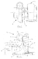
- Figures 1 and 2 illustrate a conventional centrifugal type turbocharger comprising a turbine indicated generally by the reference numeral 1, a compressor indicated generally by the reference numeral 2, and a central bearing housing indicated by the reference numeral 3.
- FIG 2a shows a cross-section through part of the compressor section of the turbocharger of Figure 1 from which it can be seen that the compressor comprises a housing defined in part by a diffuser section 4 which is part of the bearing housing casting 3 and a compressor cover 5 which defines an inlet 6 and an outlet volute 7.
- a compressor wheel 8 is mounted for rotation about a shaft 9 which extends through the bearing housing 3 to the turbine 1.
- the compressor wheel 8 comprises an array of blades 9 supported by a back disc 10 which is recessed into the diffuser section 4.
- the illustrated compressor is of a map width enhanced type in which the inlet 6 comprises a tubular inlet portion 11 around which extends a tubular intake portion 12 defining an annular chamber 13 therebetween.
- An annular slot 14 is formed through the tubular inlet portion 11 so that the chamber 13 communicates with an inducer portion of the compressor housing swept by the compressor blades 9.
- the outlet to the compressor volute 7 is via a diffuser passage 15, defined between the compressor cover 14 and diffuser section 4 of the bearing housing 3, which is an annular passage surrounding the tips of the compressor blades 9.
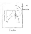
- Figure 2b is an enlargement of part of Figure 2a showing more clearly the recess 16 in the housing within which the compressor wheel back disc 10 is recessed.
- the recess is machined into the housing to leave the minimum necessary annular gap around the outside diameter of the wheel 8 (in this case the diameter of the back disc 10) to provide clearance for rotation of the compressor wheel 8.
- the diameter of the recess 16 is typically somewhere between 1.01 and 1.04 times the outside diameter of the recessed portion of compressor wheel, which in the illustrated example is the diameter of the back disc 10.
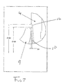
- Figure 3 is a view corresponding to Figure 2c illustrating provision of an enlarged compressor wheel recess 16 compared with that of the conventional turbocharger illustrated in Figure 2c.
- the recess is enlarged radially although is of substantially the same depth as the recess of Figure 2c.
- the diameter of the recess is 1.05 times the diameter of the recessed portion of the wheel 8 (i.e. back disc 10).
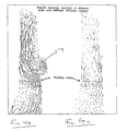
- FIGs 4a and 4b respectively show CFD results for the compressor geometries illustrated in Figures 2a and 3 at near surge operation. From this it can be seen that with the geometry according to the present invention a vortex 17 is formed in the region of the enlarged recess 16 surrounding the compressor wheel 8. This vortex 17 effectively acts as an aerodynamic "pinch" to the diffuser reducing the size of the diffuser at near surge operation which effectively delays the onset of surge.
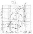
- the improvement in the surge margin is evident from comparison of the compressor maps for each of the two geometries as illustrated in Figure 5.
- This shows that the surge line 18 of the modified geometry is displaced to the left in comparison with the surge line 19 of the unmodified geometry of Figures 2c.
- the effect is particularly pronounced at relatively high pressure ratios (above about 3:1) where up to 15% additional surge margin is obtained.
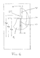
- Figure 6 illustrates an alternative embodiment of the present invention in which an annular groove 20 is formed within the compressor recess 16 in the region of the annular gap defined between the outside diameter of the recessed part of the outside diameter compressor wheel and the outside diameter of the recess.
- the depth of the recess in this region is of the order of 1.2 times the axial width of recessed portion of the compressor wheel, (typically the back disc 10).
- the depth is increased to greater than 1.5 times the axial width of the recessed portion of the compressor wheel. Tests have shown that this provides an improvement in the surge margin even if the diameter of the recess is not increased. It will however be appreciated that the increased recess depth can be combined with an increase in the recess diameter to enhance the effect. Again the improvement to the surge margin is due to the formation of a vortex within the recess around the compressor wheel at surge flow rates.
- Figure 7 shows an embodiment of the present invention in which a first groove 22 is provided within the compressor recess 16 and a second groove 23 is provided around the compressor recess which is effectively the same as providing an annular partition within the groove of the embodiment of Figure 6.
- the invention can be applied to different designs of compressor and compressor wheel.
- the compressor wheel may be recessed to a greater or lesser extent than that illustrated and may have blades configured considerably differently from those illustrated.
- the diameter of the back disc is greater than the outside diameter of the blade tips, this need not necessarily be the case.
- the blades and back disc could for example have the same outside diameter.
- the compressor wheel housing may be considerably different from that illustrated and for instance may comprise a single casting which is bolted to the bearing housing rather than being comprised jointly of the compressor cover and bearing housing.
- the particular compressor illustrated is a map width enhanced compressor design this need not necessarily be the case.
- the compressor illustrated is a vaneless design but the invention could equally be applied to the compressor provided with vanes within the diffuser.
Applications Claiming Priority (2)
| Application Number | Priority Date | Filing Date | Title |
|---|---|---|---|
| GB0004140 | 2000-02-23 | ||
| GBGB0004140.0A GB0004140D0 (en) | 2000-02-23 | 2000-02-23 | Compressor |
Publications (3)
| Publication Number | Publication Date |
|---|---|
| EP1128070A2 true EP1128070A2 (de) | 2001-08-29 |
| EP1128070A3 EP1128070A3 (de) | 2002-12-11 |
| EP1128070B1 EP1128070B1 (de) | 2005-11-02 |
Family
ID=9886158
Family Applications (1)
| Application Number | Title | Priority Date | Filing Date |
|---|---|---|---|
| EP01301654A Expired - Lifetime EP1128070B1 (de) | 2000-02-23 | 2001-02-23 | Verdichter |
Country Status (5)
| Country | Link |
|---|---|
| US (1) | US6540480B2 (de) |
| EP (1) | EP1128070B1 (de) |
| CN (1) | CN1191432C (de) |
| DE (1) | DE60114484T2 (de) |
| GB (1) | GB0004140D0 (de) |
Cited By (2)
| Publication number | Priority date | Publication date | Assignee | Title |
|---|---|---|---|---|
| WO2007078667A1 (en) * | 2005-12-15 | 2007-07-12 | Honeywell International Inc. | Ported shroud with filtered external ventilation |
| US20160097297A1 (en) * | 2014-10-07 | 2016-04-07 | Cummins Ltd. | Compressor and turbocharger |
Families Citing this family (33)
| Publication number | Priority date | Publication date | Assignee | Title |
|---|---|---|---|---|
| GB0223756D0 (en) * | 2002-10-14 | 2002-11-20 | Holset Engineering Co | Compressor |
| US7575411B2 (en) * | 2006-05-22 | 2009-08-18 | International Engine Intellectual Property Company Llc | Engine intake air compressor having multiple inlets and method |
| GB0701012D0 (en) * | 2007-01-19 | 2007-02-28 | Cummins Turbo Tech Ltd | Compressor |
| GB0718846D0 (en) * | 2007-09-27 | 2007-11-07 | Cummins Turbo Tech Ltd | Compressor |
| US8105012B2 (en) * | 2008-03-12 | 2012-01-31 | Opra Technologies B.V. | Adjustable compressor bleed system and method |
| DE102009052162B4 (de) * | 2009-11-06 | 2016-04-14 | Mtu Friedrichshafen Gmbh | Verdichteranordnung und Verfahren zur Herstellung einer solchen |
| DE102011005025A1 (de) | 2011-03-03 | 2012-09-06 | Siemens Aktiengesellschaft | Resonatorschalldämpfer für eine radiale Strömungsmaschine, insbesondere für einen Radialverdichter |
| KR101987201B1 (ko) * | 2012-06-18 | 2019-06-10 | 보르그워너 인코퍼레이티드 | 터보차저를 위한 압축기 커버 |
| CN102767538B (zh) * | 2012-06-25 | 2015-12-09 | 康跃科技股份有限公司 | 连续增压压气机 |
| CN103546033B (zh) * | 2013-10-29 | 2016-05-11 | 矽力杰半导体技术(杭州)有限公司 | 用于交错并联式开关电源的控制电路 |
| GB201420626D0 (en) * | 2014-11-20 | 2015-01-07 | Cummins Ltd | Bearing unit anti-rotation device |
| US9638138B2 (en) | 2015-03-09 | 2017-05-02 | Caterpillar Inc. | Turbocharger and method |
| US9777747B2 (en) | 2015-03-09 | 2017-10-03 | Caterpillar Inc. | Turbocharger with dual-use mounting holes |
| US9903225B2 (en) | 2015-03-09 | 2018-02-27 | Caterpillar Inc. | Turbocharger with low carbon steel shaft |
| US10066639B2 (en) | 2015-03-09 | 2018-09-04 | Caterpillar Inc. | Compressor assembly having a vaneless space |
| US9683520B2 (en) | 2015-03-09 | 2017-06-20 | Caterpillar Inc. | Turbocharger and method |
| US9810238B2 (en) | 2015-03-09 | 2017-11-07 | Caterpillar Inc. | Turbocharger with turbine shroud |
| US9879594B2 (en) | 2015-03-09 | 2018-01-30 | Caterpillar Inc. | Turbocharger turbine nozzle and containment structure |
| US9732633B2 (en) | 2015-03-09 | 2017-08-15 | Caterpillar Inc. | Turbocharger turbine assembly |
| US9822700B2 (en) | 2015-03-09 | 2017-11-21 | Caterpillar Inc. | Turbocharger with oil containment arrangement |
| US10006341B2 (en) | 2015-03-09 | 2018-06-26 | Caterpillar Inc. | Compressor assembly having a diffuser ring with tabs |
| US9650913B2 (en) | 2015-03-09 | 2017-05-16 | Caterpillar Inc. | Turbocharger turbine containment structure |
| US9739238B2 (en) | 2015-03-09 | 2017-08-22 | Caterpillar Inc. | Turbocharger and method |
| US9890788B2 (en) | 2015-03-09 | 2018-02-13 | Caterpillar Inc. | Turbocharger and method |
| US9915172B2 (en) | 2015-03-09 | 2018-03-13 | Caterpillar Inc. | Turbocharger with bearing piloted compressor wheel |
| US9752536B2 (en) | 2015-03-09 | 2017-09-05 | Caterpillar Inc. | Turbocharger and method |
| CN104895806A (zh) * | 2015-04-22 | 2015-09-09 | 上海理工大学 | 向心式压气机 |
| WO2017223363A1 (en) * | 2016-06-22 | 2017-12-28 | Steven Don Arnold | Improved inlet system for a radial compressor |
| DE102016125143A1 (de) * | 2016-12-21 | 2018-06-21 | Man Diesel & Turbo Se | Radialverdichter und Turbolader |
| US11067098B2 (en) | 2018-02-02 | 2021-07-20 | Carrier Corporation | Silencer for a centrifugal compressor assembly |
| GB201807179D0 (en) * | 2018-05-01 | 2018-06-13 | Cummins Ltd | Diffuser |
| US11261767B2 (en) | 2019-11-12 | 2022-03-01 | Fca Us Llc | Bifurcated air induction system for turbocharged engines |
| DE102020200447A1 (de) * | 2020-01-15 | 2021-07-15 | Ziehl-Abegg Se | Gehäuse für einen Ventilator und Ventilator mit einem entsprechenden Gehäuse |
Citations (5)
| Publication number | Priority date | Publication date | Assignee | Title |
|---|---|---|---|---|
| US2471174A (en) * | 1947-04-24 | 1949-05-24 | Clark Bros Co Inc | Centrifugal compressor stability means |
| GB785092A (en) * | 1955-05-23 | 1957-10-23 | York Shipley Ltd | Rotary compressor |
| FR1454330A (fr) * | 1964-11-21 | 1966-07-22 | Alfa Romeo Spa | Rotor pour machines fluidodynamiques |
| US4212585A (en) * | 1978-01-20 | 1980-07-15 | Northern Research And Engineering Corporation | Centrifugal compressor |
| GB1574942A (en) * | 1977-04-20 | 1980-09-10 | Komatsu Mfg Co Ltd | Centrifugal compressor combines with a turbine |
Family Cites Families (12)
| Publication number | Priority date | Publication date | Assignee | Title |
|---|---|---|---|---|
| US3901620A (en) * | 1973-10-23 | 1975-08-26 | Howell Instruments | Method and apparatus for compressor surge control |
| US4063848A (en) | 1976-03-24 | 1977-12-20 | Caterpillar Tractor Co. | Centrifugal compressor vaneless space casing treatment |
| DE2944183A1 (de) | 1978-11-08 | 1980-05-29 | Papst Motoren Kg | Miniaturdiagonalgeblaese mit axialem stroemungseintritt und radialem stroemungsaustritt |
| US4257733A (en) | 1978-12-26 | 1981-03-24 | Carrier Corporation | Diffuser control |
| US4504188A (en) | 1979-02-23 | 1985-03-12 | Carrier Corporation | Pressure variation absorber |
| CH646757A5 (de) | 1980-08-20 | 1984-12-14 | Sulzer Ag | Radialverdichter. |
| DE76668T1 (de) | 1981-10-06 | 1983-12-22 | Aktieselskabet Kongsberg Vaapenfabrikk, Kongsberg | Verfahren zum ableiten einer fluessigkeit in einer turbomaschine und turbomaschinen mit einer solchen vorrichtung. |
| GB2245312B (en) * | 1984-06-19 | 1992-03-25 | Rolls Royce Plc | Axial flow compressor surge margin improvement |
| DE3541508C1 (de) | 1985-11-23 | 1987-02-05 | Kuehnle Kopp Kausch Ag | Abgasturbolader |
| US5246335A (en) | 1991-05-01 | 1993-09-21 | Ishikawajima-Harimas Jukogyo Kabushiki Kaisha | Compressor casing for turbocharger and assembly thereof |
| US5497615A (en) | 1994-03-21 | 1996-03-12 | Noe; James C. | Gas turbine generator set |
| JPH0874791A (ja) | 1994-09-08 | 1996-03-19 | Nissan Motor Co Ltd | 遠心圧縮機 |
-
2000
- 2000-02-23 GB GBGB0004140.0A patent/GB0004140D0/en not_active Ceased
-
2001
- 2001-02-22 US US09/790,845 patent/US6540480B2/en not_active Expired - Lifetime
- 2001-02-23 DE DE60114484T patent/DE60114484T2/de not_active Expired - Lifetime
- 2001-02-23 EP EP01301654A patent/EP1128070B1/de not_active Expired - Lifetime
- 2001-02-23 CN CNB011173394A patent/CN1191432C/zh not_active Expired - Lifetime
Patent Citations (5)
| Publication number | Priority date | Publication date | Assignee | Title |
|---|---|---|---|---|
| US2471174A (en) * | 1947-04-24 | 1949-05-24 | Clark Bros Co Inc | Centrifugal compressor stability means |
| GB785092A (en) * | 1955-05-23 | 1957-10-23 | York Shipley Ltd | Rotary compressor |
| FR1454330A (fr) * | 1964-11-21 | 1966-07-22 | Alfa Romeo Spa | Rotor pour machines fluidodynamiques |
| GB1574942A (en) * | 1977-04-20 | 1980-09-10 | Komatsu Mfg Co Ltd | Centrifugal compressor combines with a turbine |
| US4212585A (en) * | 1978-01-20 | 1980-07-15 | Northern Research And Engineering Corporation | Centrifugal compressor |
Cited By (3)
| Publication number | Priority date | Publication date | Assignee | Title |
|---|---|---|---|---|
| WO2007078667A1 (en) * | 2005-12-15 | 2007-07-12 | Honeywell International Inc. | Ported shroud with filtered external ventilation |
| US8511083B2 (en) | 2005-12-15 | 2013-08-20 | Honeywell International, Inc. | Ported shroud with filtered external ventilation |
| US20160097297A1 (en) * | 2014-10-07 | 2016-04-07 | Cummins Ltd. | Compressor and turbocharger |
Also Published As
| Publication number | Publication date |
|---|---|
| US6540480B2 (en) | 2003-04-01 |
| EP1128070B1 (de) | 2005-11-02 |
| DE60114484D1 (de) | 2005-12-08 |
| US20020012586A1 (en) | 2002-01-31 |
| EP1128070A3 (de) | 2002-12-11 |
| DE60114484T2 (de) | 2006-08-03 |
| CN1312439A (zh) | 2001-09-12 |
| GB0004140D0 (en) | 2000-04-12 |
| CN1191432C (zh) | 2005-03-02 |
Similar Documents
| Publication | Publication Date | Title |
|---|---|---|
| EP1128070B1 (de) | Verdichter | |
| JP4717465B2 (ja) | 圧縮機 | |
| EP1853825B1 (de) | Turbolader mit öffnung in der abdeckung der zweiten stufe des kompressors | |
| JP4317327B2 (ja) | 低速度高圧縮比ターボチャージャ | |
| EP0526965B1 (de) | Verdichtergehäuse für Turbolader | |
| CA2496543C (en) | Recirculation structure for a turbocompressor | |
| US6168375B1 (en) | Spring-loaded vaned diffuser | |
| US6073447A (en) | Turbocharger | |
| US5813834A (en) | Centrifugal fan | |
| US5236301A (en) | Centrifugal compressor | |
| US9140267B2 (en) | Compressor | |
| EP0425651A1 (de) | Zapfluftöffnungen für ein kompressorgehäuse | |
| GB2032523A (en) | Controlled flow gas compressor | |
| GB2277129A (en) | Exhaust gas turbocharger | |
| EP3088700B1 (de) | Turbine | |
| US6792755B2 (en) | High-pressure ratio turbocharger | |
| JP4972259B2 (ja) | 遠心ポンプ | |
| US6920754B2 (en) | High-pressure ratio turbocharger | |
| CN108431371B (zh) | 涡轮增压器压缩机和方法 | |
| EP2029896B1 (de) | Verdichter | |
| CN113557354B (zh) | 可变容量型增压器 | |
| CN108431385B (zh) | 涡轮增压器压缩机和方法 | |
| JP5747472B2 (ja) | ターボ形圧縮機 | |
| JPS6118161Y2 (de) | ||
| JPS59168296A (ja) | 多段軸流圧縮機のサ−ジング防止装置 |
Legal Events
| Date | Code | Title | Description |
|---|---|---|---|
| PUAI | Public reference made under article 153(3) epc to a published international application that has entered the european phase |
Free format text: ORIGINAL CODE: 0009012 |
|
| AK | Designated contracting states |
Kind code of ref document: A2 Designated state(s): AT BE CH CY DE DK ES FI FR GB GR IE IT LI LU MC NL PT SE TR |
|
| AX | Request for extension of the european patent |
Free format text: AL;LT;LV;MK;RO;SI |
|
| PUAL | Search report despatched |
Free format text: ORIGINAL CODE: 0009013 |
|
| AK | Designated contracting states |
Kind code of ref document: A3 Designated state(s): AT BE CH CY DE DK ES FI FR GB GR IE IT LI LU MC NL PT SE TR |
|
| AX | Request for extension of the european patent |
Free format text: AL;LT;LV;MK;RO;SI |
|
| RIC1 | Information provided on ipc code assigned before grant |
Free format text: 7F 04D 27/02 A, 7F 04D 25/04 B, 7F 04D 29/68 B, 7F 04D 29/44 B |
|
| 17P | Request for examination filed |
Effective date: 20030314 |
|
| AKX | Designation fees paid |
Designated state(s): DE FR GB |
|
| 17Q | First examination report despatched |
Effective date: 20041203 |
|
| GRAP | Despatch of communication of intention to grant a patent |
Free format text: ORIGINAL CODE: EPIDOSNIGR1 |
|
| GRAS | Grant fee paid |
Free format text: ORIGINAL CODE: EPIDOSNIGR3 |
|
| GRAA | (expected) grant |
Free format text: ORIGINAL CODE: 0009210 |
|
| AK | Designated contracting states |
Kind code of ref document: B1 Designated state(s): DE FR GB |
|
| REG | Reference to a national code |
Ref country code: GB Ref legal event code: FG4D |
|
| REF | Corresponds to: |
Ref document number: 60114484 Country of ref document: DE Date of ref document: 20051208 Kind code of ref document: P |
|
| ET | Fr: translation filed | ||
| PLBE | No opposition filed within time limit |
Free format text: ORIGINAL CODE: 0009261 |
|
| STAA | Information on the status of an ep patent application or granted ep patent |
Free format text: STATUS: NO OPPOSITION FILED WITHIN TIME LIMIT |
|
| 26N | No opposition filed |
Effective date: 20060803 |
|
| REG | Reference to a national code |
Ref country code: FR Ref legal event code: CD Owner name: CUMMINS TURBO TECHNOLOGIES LIMITED Effective date: 20130924 |
|
| REG | Reference to a national code |
Ref country code: FR Ref legal event code: PLFP Year of fee payment: 16 |
|
| REG | Reference to a national code |
Ref country code: FR Ref legal event code: PLFP Year of fee payment: 17 |
|
| REG | Reference to a national code |
Ref country code: FR Ref legal event code: PLFP Year of fee payment: 18 |
|
| REG | Reference to a national code |
Ref country code: GB Ref legal event code: 732E Free format text: REGISTERED BETWEEN 20180315 AND 20180326 |
|
| REG | Reference to a national code |
Ref country code: DE Ref legal event code: R081 Ref document number: 60114484 Country of ref document: DE Owner name: CUMMINS LTD., STAINES, GB Free format text: FORMER OWNER: HOLSET ENGINEERING CO. LTD., HUDDERSFIELD, WEST YORKSHIRE, GB |
|
| REG | Reference to a national code |
Ref country code: FR Ref legal event code: TP Owner name: CUMMINS LTD., GB Effective date: 20180903 |
|
| PGFP | Annual fee paid to national office [announced via postgrant information from national office to epo] |
Ref country code: GB Payment date: 20200227 Year of fee payment: 20 Ref country code: DE Payment date: 20200227 Year of fee payment: 20 |
|
| PGFP | Annual fee paid to national office [announced via postgrant information from national office to epo] |
Ref country code: FR Payment date: 20200225 Year of fee payment: 20 |
|
| REG | Reference to a national code |
Ref country code: DE Ref legal event code: R071 Ref document number: 60114484 Country of ref document: DE |
|
| REG | Reference to a national code |
Ref country code: GB Ref legal event code: PE20 Expiry date: 20210222 |
|
| PG25 | Lapsed in a contracting state [announced via postgrant information from national office to epo] |
Ref country code: GB Free format text: LAPSE BECAUSE OF EXPIRATION OF PROTECTION Effective date: 20210222 |