EP1127984A1 - Planar light emitting device and light-emitting guide - Google Patents
Planar light emitting device and light-emitting guide Download PDFInfo
- Publication number
- EP1127984A1 EP1127984A1 EP99940558A EP99940558A EP1127984A1 EP 1127984 A1 EP1127984 A1 EP 1127984A1 EP 99940558 A EP99940558 A EP 99940558A EP 99940558 A EP99940558 A EP 99940558A EP 1127984 A1 EP1127984 A1 EP 1127984A1
- Authority
- EP
- European Patent Office
- Prior art keywords
- light
- emitting
- reflecting
- area
- incident
- Prior art date
- Legal status (The legal status is an assumption and is not a legal conclusion. Google has not performed a legal analysis and makes no representation as to the accuracy of the status listed.)
- Withdrawn
Links
- 239000004925 Acrylic resin Substances 0.000 description 5
- 229920000178 Acrylic resin Polymers 0.000 description 5
- 239000000463 material Substances 0.000 description 3
- 230000005611 electricity Effects 0.000 description 2
- 238000000034 method Methods 0.000 description 2
- 229910052754 neon Inorganic materials 0.000 description 2
- GKAOGPIIYCISHV-UHFFFAOYSA-N neon atom Chemical compound [Ne] GKAOGPIIYCISHV-UHFFFAOYSA-N 0.000 description 2
- 239000012780 transparent material Substances 0.000 description 2
- 239000004793 Polystyrene Substances 0.000 description 1
- 239000000853 adhesive Substances 0.000 description 1
- 230000001070 adhesive effect Effects 0.000 description 1
- 238000003491 array Methods 0.000 description 1
- 230000015572 biosynthetic process Effects 0.000 description 1
- 230000000295 complement effect Effects 0.000 description 1
- 239000011521 glass Substances 0.000 description 1
- 238000001746 injection moulding Methods 0.000 description 1
- 238000003754 machining Methods 0.000 description 1
- 230000003287 optical effect Effects 0.000 description 1
- 239000004417 polycarbonate Substances 0.000 description 1
- 229920000515 polycarbonate Polymers 0.000 description 1
- 229920002223 polystyrene Polymers 0.000 description 1
- 239000011347 resin Substances 0.000 description 1
- 229920005989 resin Polymers 0.000 description 1
Images


Classifications
-
- F—MECHANICAL ENGINEERING; LIGHTING; HEATING; WEAPONS; BLASTING
- F21—LIGHTING
- F21K—NON-ELECTRIC LIGHT SOURCES USING LUMINESCENCE; LIGHT SOURCES USING ELECTROCHEMILUMINESCENCE; LIGHT SOURCES USING CHARGES OF COMBUSTIBLE MATERIAL; LIGHT SOURCES USING SEMICONDUCTOR DEVICES AS LIGHT-GENERATING ELEMENTS; LIGHT SOURCES NOT OTHERWISE PROVIDED FOR
- F21K9/00—Light sources using semiconductor devices as light-generating elements, e.g. using light-emitting diodes [LED] or lasers
- F21K9/60—Optical arrangements integrated in the light source, e.g. for improving the colour rendering index or the light extraction
- F21K9/61—Optical arrangements integrated in the light source, e.g. for improving the colour rendering index or the light extraction using light guides
-
- G—PHYSICS
- G02—OPTICS
- G02B—OPTICAL ELEMENTS, SYSTEMS OR APPARATUS
- G02B6/00—Light guides; Structural details of arrangements comprising light guides and other optical elements, e.g. couplings
- G02B6/0001—Light guides; Structural details of arrangements comprising light guides and other optical elements, e.g. couplings specially adapted for lighting devices or systems
- G02B6/0011—Light guides; Structural details of arrangements comprising light guides and other optical elements, e.g. couplings specially adapted for lighting devices or systems the light guides being planar or of plate-like form
- G02B6/0033—Means for improving the coupling-out of light from the light guide
- G02B6/0035—Means for improving the coupling-out of light from the light guide provided on the surface of the light guide or in the bulk of it
- G02B6/0038—Linear indentations or grooves, e.g. arc-shaped grooves or meandering grooves, extending over the full length or width of the light guide
-
- E—FIXED CONSTRUCTIONS
- E01—CONSTRUCTION OF ROADS, RAILWAYS, OR BRIDGES
- E01F—ADDITIONAL WORK, SUCH AS EQUIPPING ROADS OR THE CONSTRUCTION OF PLATFORMS, HELICOPTER LANDING STAGES, SIGNS, SNOW FENCES, OR THE LIKE
- E01F9/00—Arrangement of road signs or traffic signals; Arrangements for enforcing caution
- E01F9/60—Upright bodies, e.g. marker posts or bollards; Supports for road signs
- E01F9/604—Upright bodies, e.g. marker posts or bollards; Supports for road signs specially adapted for particular signalling purposes, e.g. for indicating curves, road works or pedestrian crossings
- E01F9/619—Upright bodies, e.g. marker posts or bollards; Supports for road signs specially adapted for particular signalling purposes, e.g. for indicating curves, road works or pedestrian crossings with reflectors; with means for keeping reflectors clean
-
- E—FIXED CONSTRUCTIONS
- E01—CONSTRUCTION OF ROADS, RAILWAYS, OR BRIDGES
- E01F—ADDITIONAL WORK, SUCH AS EQUIPPING ROADS OR THE CONSTRUCTION OF PLATFORMS, HELICOPTER LANDING STAGES, SIGNS, SNOW FENCES, OR THE LIKE
- E01F9/00—Arrangement of road signs or traffic signals; Arrangements for enforcing caution
- E01F9/60—Upright bodies, e.g. marker posts or bollards; Supports for road signs
- E01F9/658—Upright bodies, e.g. marker posts or bollards; Supports for road signs characterised by means for fixing
- E01F9/669—Upright bodies, e.g. marker posts or bollards; Supports for road signs characterised by means for fixing for fastening to safety barriers or the like
-
- F—MECHANICAL ENGINEERING; LIGHTING; HEATING; WEAPONS; BLASTING
- F21—LIGHTING
- F21V—FUNCTIONAL FEATURES OR DETAILS OF LIGHTING DEVICES OR SYSTEMS THEREOF; STRUCTURAL COMBINATIONS OF LIGHTING DEVICES WITH OTHER ARTICLES, NOT OTHERWISE PROVIDED FOR
- F21V7/00—Reflectors for light sources
- F21V7/005—Reflectors for light sources with an elongated shape to cooperate with linear light sources
-
- G—PHYSICS
- G02—OPTICS
- G02B—OPTICAL ELEMENTS, SYSTEMS OR APPARATUS
- G02B5/00—Optical elements other than lenses
- G02B5/12—Reflex reflectors
- G02B5/122—Reflex reflectors cube corner, trihedral or triple reflector type
- G02B5/124—Reflex reflectors cube corner, trihedral or triple reflector type plural reflecting elements forming part of a unitary plate or sheet
-
- G—PHYSICS
- G02—OPTICS
- G02B—OPTICAL ELEMENTS, SYSTEMS OR APPARATUS
- G02B6/00—Light guides; Structural details of arrangements comprising light guides and other optical elements, e.g. couplings
- G02B6/0001—Light guides; Structural details of arrangements comprising light guides and other optical elements, e.g. couplings specially adapted for lighting devices or systems
- G02B6/0011—Light guides; Structural details of arrangements comprising light guides and other optical elements, e.g. couplings specially adapted for lighting devices or systems the light guides being planar or of plate-like form
- G02B6/0013—Means for improving the coupling-in of light from the light source into the light guide
- G02B6/0023—Means for improving the coupling-in of light from the light source into the light guide provided by one optical element, or plurality thereof, placed between the light guide and the light source, or around the light source
- G02B6/0031—Reflecting element, sheet or layer
-
- G—PHYSICS
- G02—OPTICS
- G02B—OPTICAL ELEMENTS, SYSTEMS OR APPARATUS
- G02B6/00—Light guides; Structural details of arrangements comprising light guides and other optical elements, e.g. couplings
- G02B6/0001—Light guides; Structural details of arrangements comprising light guides and other optical elements, e.g. couplings specially adapted for lighting devices or systems
- G02B6/0011—Light guides; Structural details of arrangements comprising light guides and other optical elements, e.g. couplings specially adapted for lighting devices or systems the light guides being planar or of plate-like form
- G02B6/0033—Means for improving the coupling-out of light from the light guide
- G02B6/0035—Means for improving the coupling-out of light from the light guide provided on the surface of the light guide or in the bulk of it
- G02B6/0045—Means for improving the coupling-out of light from the light guide provided on the surface of the light guide or in the bulk of it by shaping at least a portion of the light guide
- G02B6/0046—Tapered light guide, e.g. wedge-shaped light guide
-
- G—PHYSICS
- G02—OPTICS
- G02B—OPTICAL ELEMENTS, SYSTEMS OR APPARATUS
- G02B6/00—Light guides; Structural details of arrangements comprising light guides and other optical elements, e.g. couplings
- G02B6/0001—Light guides; Structural details of arrangements comprising light guides and other optical elements, e.g. couplings specially adapted for lighting devices or systems
- G02B6/0011—Light guides; Structural details of arrangements comprising light guides and other optical elements, e.g. couplings specially adapted for lighting devices or systems the light guides being planar or of plate-like form
- G02B6/0066—Light guides; Structural details of arrangements comprising light guides and other optical elements, e.g. couplings specially adapted for lighting devices or systems the light guides being planar or of plate-like form characterised by the light source being coupled to the light guide
- G02B6/0073—Light emitting diode [LED]
-
- F—MECHANICAL ENGINEERING; LIGHTING; HEATING; WEAPONS; BLASTING
- F21—LIGHTING
- F21V—FUNCTIONAL FEATURES OR DETAILS OF LIGHTING DEVICES OR SYSTEMS THEREOF; STRUCTURAL COMBINATIONS OF LIGHTING DEVICES WITH OTHER ARTICLES, NOT OTHERWISE PROVIDED FOR
- F21V2200/00—Use of light guides, e.g. fibre optic devices, in lighting devices or systems
- F21V2200/20—Use of light guides, e.g. fibre optic devices, in lighting devices or systems of light guides of a generally planar shape
-
- F—MECHANICAL ENGINEERING; LIGHTING; HEATING; WEAPONS; BLASTING
- F21—LIGHTING
- F21Y—INDEXING SCHEME ASSOCIATED WITH SUBCLASSES F21K, F21L, F21S and F21V, RELATING TO THE FORM OR THE KIND OF THE LIGHT SOURCES OR OF THE COLOUR OF THE LIGHT EMITTED
- F21Y2103/00—Elongate light sources, e.g. fluorescent tubes
- F21Y2103/10—Elongate light sources, e.g. fluorescent tubes comprising a linear array of point-like light-generating elements
-
- F—MECHANICAL ENGINEERING; LIGHTING; HEATING; WEAPONS; BLASTING
- F21—LIGHTING
- F21Y—INDEXING SCHEME ASSOCIATED WITH SUBCLASSES F21K, F21L, F21S and F21V, RELATING TO THE FORM OR THE KIND OF THE LIGHT SOURCES OR OF THE COLOUR OF THE LIGHT EMITTED
- F21Y2115/00—Light-generating elements of semiconductor light sources
- F21Y2115/10—Light-emitting diodes [LED]
-
- G—PHYSICS
- G02—OPTICS
- G02B—OPTICAL ELEMENTS, SYSTEMS OR APPARATUS
- G02B6/00—Light guides; Structural details of arrangements comprising light guides and other optical elements, e.g. couplings
- G02B6/0001—Light guides; Structural details of arrangements comprising light guides and other optical elements, e.g. couplings specially adapted for lighting devices or systems
- G02B6/0011—Light guides; Structural details of arrangements comprising light guides and other optical elements, e.g. couplings specially adapted for lighting devices or systems the light guides being planar or of plate-like form
- G02B6/0033—Means for improving the coupling-out of light from the light guide
- G02B6/0035—Means for improving the coupling-out of light from the light guide provided on the surface of the light guide or in the bulk of it
- G02B6/0036—2-D arrangement of prisms, protrusions, indentations or roughened surfaces
-
- G—PHYSICS
- G02—OPTICS
- G02B—OPTICAL ELEMENTS, SYSTEMS OR APPARATUS
- G02B6/00—Light guides; Structural details of arrangements comprising light guides and other optical elements, e.g. couplings
- G02B6/0001—Light guides; Structural details of arrangements comprising light guides and other optical elements, e.g. couplings specially adapted for lighting devices or systems
- G02B6/0011—Light guides; Structural details of arrangements comprising light guides and other optical elements, e.g. couplings specially adapted for lighting devices or systems the light guides being planar or of plate-like form
- G02B6/0033—Means for improving the coupling-out of light from the light guide
- G02B6/005—Means for improving the coupling-out of light from the light guide provided by one optical element, or plurality thereof, placed on the light output side of the light guide
- G02B6/0055—Reflecting element, sheet or layer
Definitions
- This invention relates to a planar light-emitting device, particularly to a planar light-emitting device useful for a light-emitting guide that is placed at the side edge of a road or on the wall of a tunnel to show drivers the position thereof.
- This invention further relates to a light-emitting guide provided with the planar light-emitting device.
- planar light-emitting guides emit light in the forward direction with almost even luminous intensity. Consequently the luminous intensity of the light seen from at an angle with the light-emitting face is not very high.
- planar light-emitting guides had to be placed at positions projecting out from the side edge of a road or the wall of a tunnel so as that the light-emitting face can be seen frontally from running automobiles.
- planar light-emitting guides when the conventional planar light-emitting guides are placed inside a tunnel, typically, electricity is sent to light sources, for example light-emitting diodes, to make them give forth light. If the electric wires are down and electricity cannot be fed to the light sources, the guides do not emit light, which leads to the deprivation of the guides' function.
- light sources for example light-emitting diodes
- An objective of the invention is to provide a planar light-emitting device that can be placed at the side edge of a road or on the wall of a tunnel and that does not lose its function when the electric wires are down, and a light-emitting guide that is provided with the planar light-emitting device and that can advantageously be used inside tunnels.
- This invention relates to (1) a planar light-emitting device which comprises at least one substantially planar elongated light-emitting area, and at least one elongated incident light-reflecting area placed alongside said light-emitting area on substantially the same plane as that where said light-emitting area is on, wherein said light-emitting area has a function of emitting light along the longitudinal axis of said light-emitting area at an angle with an imaginary line perpendicular to said light-emitting area, and said incident light-reflecting area has a function of reflecting a light incident thereon along the longitudinal axis of said incident light-reflecting area at an angle with an imaginary line perpendicular to said incident light-reflecting area in the direction of the incidence.
- Preferred embodiments of said planar light-emitting device(1) include:
- This invention further includes a light-emitting guide comprising said planar light-emitting device recited in any one of (1)-(10) wherein the respective axes of the light-emitting area and incident light-reflecting area are placed generally horizontally.
- the reference numerals denote the followings.
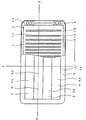
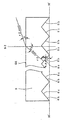
- the planar light-emitting device of Example 1 comprises planar light emitter 3 comprising light transmissible plate 1, light sources 2 placed along end faces 1a of light transmissible plate 1 and light-emitting face 1b, which will be explained hereafter, formed on one face of light-transmissible plate 1, and housing 4 accommodating planar light emitter 3.
- housing 4 is shown in a partially cutaway view where face 4a, and part of light transmissible window 5 and incident light-reflecting member 6 are cut away.
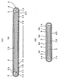
- (A) shows a cross-sectional view taken on line X-X of Figure 1
- (B) a cross-sectional view taken on line Y-Y of the same figure.
- light transmissible plate 1 can be used a rectangular planar member having light transmissibility such as "a plate member having light transmissibility" taught by Unexamined Japanese Patent Application Publication No. 10-232633(1998).
- Light transmissible plate 1 may be a colorless transparent one or colored transparent one.
- Examples of the materials for light transmissible plate 1 are transparent synthesized resins such as acrylic resins, polycarbonates and polystyrenes, and other transparent materials such as various kinds of glass.
- the thickness of light transmissible plate 1 is preferably from about 6 mm to about 10 mm. However, the thickness is not limited to this range.
- light sources 2 are placed along a pair of end faces 1a, which form the shorter sides of light transmissible plate 1.
- light sources 2 are employed light-emitting diodes arranged in a line respectively along end faces 1a. With light sources 2 are connected a lighting circuit and a power source, which are not shown in the figures, to turn on light sources.
- light sources 2 are cold-cathode tubes, electroluminescent light sources, fluorescent lamps, mercury-arc lamps, neon tubes and incandescent lamps.
- Light sources 2 may be flickered by flickering means such as flickering circuits.
- flickering means such as flickering circuits.
- plural triangular grooves 1d are formed on the opposite face of light-emitting face 1b, i.e. backside 1c of light transmissible plate 1. These triangular grooves are arranged perpendicularly to the longitudinal sides, that is, along the transverse sides, of light transmissible plate 1 at regular spaces.
- the length of each of the triangular grooves 1d is substantially the same as the width, that is, the length of the side perpendicular to the longitudinal side of light transmissible plate 1.
- the triangular grooves 1d have a function to make the rays emitted by light sources 2 into light transmissible plate 1 outgo from light-emitting face 1b at an angle with an imaginary line perpendicular to light-emitting face 1b.
- the grooves have a function to make the light outgo at an angle of greater than 0° and less than 90° with light-emitting face 1b.
- inner walls 1e of triangular grooves 1d correspond to the emitted light-reflecting face of the planar light emitter when the planar light-emitting device of the invention is provided with the planar light emitter.
- the luminous intensity or the amount of the outgoing light becomes larger.
- the luminous intensity of the light emitted into light transmissible plate 1 becomes lower, as the light goes near to the center of the plate from end faces 1a.
- both of the luminous intensities and the outgoing angles of the outgoing rays are substantially constant irrespective of the positions on emitted light-reflecting face 1b where the rays are made to outgo.
- One of the methods to form triangular grooves 1d on light transmissible plate 1 is to irradiate a laser beam having a diameter of about 0.2 to 0.3 mm onto backside 1c perpendicularly thereto and to scan it on the backside along the transverse side of light transmissible plate 1.
- Other methods include the formation by machining work or injection molding.
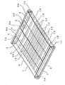
- Housing 4 accommodating planar light emitter 3 is not light transmissible, and as shown in Figures 1 and 2, has a shape of rectangular parallelopiped of which height is small compared with the length and width. Housing 4 accommodates planar light emitter 3 including light transmissible plate 1 and light sources 2, and a lighting circuit for lighting light sources 2. Light transmissible plate 1 is placed inside housing 4 along the longitudinal side thereof.
- housing 4 which faces light-emitting face 1b of light transmissible plate 1
- an opening In upper face 4a so as to fill the opening are set alternately along the longitudinal side of housing 4 light transmissible window 5 and incident light-reflecting member 6.
- Light transmissible window 5 is an elongated rectangular plate member and through it the light from light-emitting face 1b outgoes.
- Incident light-reflecting member 6 is also an elongated rectangular plate member and on the backside of it is formed incident light-reflecting face 6a.
- incident light-reflecting member 6 is also an elongated rectangular plate member and on the backside of it is formed incident light-reflecting face 6a.
- the term "an elongated rectangular” means a rectangular of which length is greater than the width.
- light-emitting area 5A comprises the face of light transmissible window 5, and incident light-reflecting area 6A does the face of incident light-reflecting member 6.
- the length of light transmissible window 5 and that of incident light-reflecting member 6 are substantially the same as that of light transmissible plate 1.
- materials of light transmissible window 5 and incident light-reflecting member 6 may be used those that have been mentioned for the materials of light transmissible plate 1. Both the window and the member may be colorless transparent ones or colored transparent ones.
- the planar light-emitting device of Example 1 has two light transmissible windows 5 and two incident light-reflecting members 6.
- the respective numbers of the windows and members are not limited.
- a plate-like member having light transmissible windows 5 and incident light-reflecting members 6 may be formed from a transparent plate.
- incident light-reflecting faces 6a which are made in stripes along the longitudinal side of the plate.
- the plate may be made of the transparent materials used for light transmissible plate 1.
- the parts, on the backsides of which are formed incident light-reflecting faces 6a function as incident light-reflecting areas 6A.
- the other parts of the plate-like member function as light transmissible windows 5, which correspond to light-emitting areas 5A. Therefore the light outgoing from planar light emitter 3 goes through those parts of the plate-like member on which incident light-reflecting faces 6a are not formed.
- incident light-reflecting members 6 may be stuck to the surface of a colorless or colored transparent plate along the longitudinal sides thereof at equal spaces and the obtained plate may be set in upper face 4a of housing 4 to fill the opening.
- the parts where incident light-reflecting members are not stuck function as light transmissible windows 5, or light-emitting areas 5A.
- At least upper face 4a of housing 4 may be made colorless or colored transparent, and incident light-reflecting members 6 may be stuck onto the face along the longitudinal sides thereof at equal spaces.
- the parts where incident light-reflecting members are not stuck function as light transmissible windows 5, or light-emitting areas 5A.
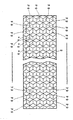
- incident light-reflecting member 6 used for the planar light-emitting device of Example 1 may be employed, for example, the member 6 shown in Figure 3.
- This member has on its backside, which is opposite to the face upon which incident light comes, plural triangular grooves 6b that are arranged side by side and parallel with the transverse sides of the member.
- Incident light-reflecting faces 6a are made of inner walls 6cof triangular grooves 6b.
- the members When light comes upon incident light-reflecting members 6 at an incident angle of ⁇ , the members reflect the light in the incident direction. Reflecting incident light in the incident direction may sometimes be called “retroreflection” hereafter.
- the incident angle ⁇ can also be called the retroreflection angle.
- incident light-reflecting member 6 is the member shown in Figure 4.
- This member 6 has on its backside concavities 6d, each of which is made of three touching square-shaped or rhombus-shaped reflecting faces 6e. These concavities are arranged side by side so as to make a honeycomb.
- concavities 6d are arranged side by side so as to make a honeycomb.
- three reflecting faces 6e one is arranged to face the transverse side of incident light- reflecting member 6 and other two faces are respectively joined with the one face at an angle of 60° .
- incident light-reflecting face 6a is made of the inner walls of concavities 6d. Similarly to the member 6 shown in Figure 3, this face reflects incident light coming thereupon at the retroreflection angle.
- incident light-reflecting member 6 is a transparent plate having on its backside, for example, a honeycomb arrangement of triangular pyramid-shaped or circular cone-shaped concavities.
- incident light-reflecting member 6 when incident light-reflecting member 6 is stuck onto a light transmissible plate-like member or a light transmissible upper face 4a of housing 4, may be employed a sheet-like incident light-reflecting member 6 having incident light-reflecting face 6a on its one face, instead of the plate-like member 6.
- the planar light-emitting device of Example 1 is usually used for guiding devices that are placed along roads or inside tunnels. As will be explained hereafter, this device is fixed onto the inner wall of a tunnel so that light-emitting areas 5A and incident light-reflecting areas 6A are placed parallel to the inner wall and the axes of the respective areas are generally horizontal.
- vertical angle ⁇ of triangular groove 1d is decided so that the light emitted from light sources 2 into the inside of light transmissible plate 1 is made to outgo at an angle ⁇ of more than 0° to less than 90°, preferably more than 0° to not more than 30°, more preferably 5° to 20°, particularly preferably 10° to 20° .
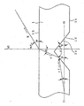
- Figure 5 shows a passage of a ray emitted into the inside of light transmissible plate 1.
- r1 denotes a passage of a ray emitted from light source 2, ⁇ an angle made by passage r1 and imaginary plane H parallel with both light-emitting face 1b and backside 1c, and R a passage of the ray when it outgoes from light-emitting face 1b.
- n1 When light transmissible plate 1 is made of an acrylic resin, since the acrylic resin typically has a refraction index of 1.49, n1 may be regarded as 1.49.
- the refraction index of air (n2) is 1.00.
- angle ⁇ since angle ⁇ is from more than 0° to less than 90°, when angle ⁇ is 0°, vertical angle ⁇ is more than 90° to less than 132.1°, which is calculated from formula (3).
- angle ⁇ is from more than 0° to less than 30°
- vertical angle ⁇ is from not less than 125.5° to less than 132.1°.
- Angle ⁇ is considered to be usually in the range of -15° to +15° . Therefore, when angle ⁇ is from more than 0° to less than 30° and angle ⁇ is -15°, vertical angle ⁇ is from not less than 110.5° to less than 117.1°, from formula (3). When angle ⁇ is +15°, vertical angle ⁇ is from not less than 140.5° to less than 147.1°.
- the light outgoes from light-emitting face 1b at an angle ⁇ of the range. Since light-emitting area 5A comprises light transmissible window 5, the light goes out through light-emitting area 5A at the angle ⁇ .
- vertical angle ⁇ of triangular grooves 6b on incident light-reflecting member 6 is decided in the following steps.
- Figure 6 shows a passage of an incident ray inside incident light-reflecting member 6.
- r2 denotes a passage of the incident ray.
- the refractive index of incident light-reflecting member 6 is n3
- the angle made by passage r2 and imaginary line h2 perpendicular to the upper face of incident light-reflecting member 6 is named ⁇ 3
- the angle made by inner wall 6c of triangular groove 6b and imaginary plane H' parallel with the upper face of incident light-reflecting member 6 is named ⁇
- Retroreflection angle ⁇ in Example 1 is, similar to outgoing angle ⁇ , from more than 0° to less than 90° , preferably from more than 0° to not more than 30°, more preferably from 5° to 20° , particularly preferably from 10° to 20°. This angle is typically around 16.5°.
- n3 may be regarded as 1. 49.
- angle ⁇ is from more than 0° to not more than 30°
- angle ⁇ 3 or angle ⁇ is from not less than 35.5° to less than 42.2° , which is calculated from formulae (4) and (5).
- vertical angle ⁇ of triangular groove 6b is from more than 95.7° to not more than 108.9°.
- angle ⁇ 3 is about 40° and therefore vertical angle ⁇ is about 100°.
- the planar light-emitting device of Example 1 may be used as a guide showing the inner wall of a tunnel or the side edge of a road when it is fixed onto the inner wall or placed at the side edge.
- planar light-emitting device is used as a light-emitting guide inside a tunnel.
- A denotes a planar light-emitting device in accordance of Example 1.
- planar light-emitting device A is fixed to inner wall B of the tunnel through bottom face 4b of housing 4 and a fixing support, which is not shown, so that both light transmissible window 5 and incident light-reflecting member 6 of device A extend along road C, which is the road running through the tunnel, or generally horizontally and the transverse sides of housing 4 are vertical to road C.
- D means the center line drawn on road C.
- device A substantially does not project from the surface of the inner wall, it seldom interferes in the traffic.
- light-emitting areas 5A comprising light transmissible windows 5 extend horizontally, light beams having a high luminous intensity is emitted from the surfaces of areas 5A in the horizontal direction to automobiles and motorcycles running through the tunnel. Still further, since light-emitting areas 5A are seen long from side to side from the drivers, the emitted light beams can be seen well from far away.
- incident light-reflecting areas 6A comprising incident light-reflecting members 6 extend horizontally, light beams from the automobiles and motorcycles are incident on incident light-reflecting areas 6A obliquely at a particular angle and retroreflected in the incident direction or toward the automobiles and motorcycles with a high luminous intensity.
- incident light-reflecting areas 6A are also seen long from side to side from the drivers, the retroreflected light can be seen well from far away.
- the planar light-emitting device of Example 1 still functions as a guide showing the positions of the walls of the tunnel.
- the planar light-emitting device of this example shows an embodiment wherein the device has the planar light emitter and further includes a light-emitting area comprising a part of the light-emitting face and an incident light reflecting area comprising the incident light-reflecting member placed on the light-emitting face.
- the device of Example 2 has a planar light emitter that is essentially the same as planar light emitter 3 of Example 1.
- the reference numerals that are also used in Figures 1-7 denote respectively the same elements as the elements meant in the precedent figures, unless mentioned otherwise.
- Light transmissible plate 1 of Example 2 is essentially the same as that of Example 1, except that triangular grooves Id are formed over the entire width of light transmissible plate 1.
- light sources 2 are cylindrical cold-cathode tubes extending along the respective end faces la of light transmissible plate 1.
- Other examples of light sources 2 are arrays of light-emitting diodes similar to those used in the embodiment of Example 1, electroluminescent light sources, fluorescent lamps, mercury-arc lamps, neon tubes and incandescent lamps. Similar to those of Example 1, light sources 2 are connected with flickering circuits and a power source, which are not shown. What is different from the embodiment of Figure 1 is that the sources other than the parts facing end faces 1a are covered with light-untransmissible light source-covers 7.
- two planar rectangular incident light-reflecting members 6 are arranged parallel with each other along the longitudinal sides of plate 1.
- Two incident light-reflecting areas 6A are comprised of these two incident light-reflecting members 6.
- two light-emitting areas 5A are comprised of those parts of light-emitting face 1b that are not covered with incident light-reflecting members 6.
- Incident light-reflecting members 6 are so placed on light-emitting face 1b that incident light-reflecting areas 6A and light-emitting areas 5A are arranged alternately along the longitudinal sides of light transmissible plate 1.
- incident light-reflecting member 6 can be used, for example, the incident light-reflecting member shown in Figure 3 as well as that shown in Figure 4.
- the angle at which the outgoing light goes out of light-emitting areas 5A, the retroreflection angle at which the light is reflected in incident light-reflecting areas 6A, the passage of rays emitted from light sources 2 into the inside of light transmissible plate 1, and the reflection passage along which the incident rays are reflected by incident light-reflecting member 6 in the planar light-emitting device of Example 2 are basically the same as those in the device of Example 1, the spaces between triangular grooves 1b and the vertical angles thereof and the vertical angles of triangular grooves 6b may be decided in the same way.
- the planar light-emitting device of Example 2 may also be used as a light-emitting guide placed, for example, inside tunnels. As shown in Figure 7, the device can be fixed onto the inner wall of a tunnel so that the axes of light-emitting areas 5A and incident light-reflecting areas 6A are parallel with the road, or generally horizontally.
- the device of this example can also emit light beams having a high luminous intensity to automobiles and motorcycles running through the tunnel. Further, light beams from the automobiles and motorcycles are retroreflected toward them.
- the device of Example 2 does not have housings, and therefore the thickness of the device can be reduced.
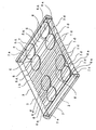
- This example shows a planar light-emitting device that has incident light-reflecting areas comprising disk-shaped incident light-reflecting members arranged in a double line, instead of those employed in Example 2.
- the planar light-emitting device of Example 3 has plural disk-shaped incident light-reflecting members 6 arranged on light-emitting face 1b in a double line along the longitudinal sides of light transmissible plate 1 with a space between the lines.
- incident light-reflecting areas 6A comprise each line of members 6, and light-emitting areas 5A comprise parts between the lines.
- the shape of the members 6 may be tetragons, polygons, etc. other than the circle shown in Figure 9.
- a preferable incident light-reflecting member 6 of this example has optical grooves or concavities similar to that shown in Figure 3 or 4.
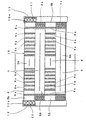
- the planar light-emitting device of Example 4 have light transmissible plates 8 substantially the same as plate 1 of Example 1, and plate-like incident light-reflecting members 9 substantially the same as member 6 of Example 9.
- Two plates 8 and two members 9 are arranged alternately along the longitudinal sides thereof and bonded together to form a planar rectangular light-emitting plate 10.
- the transverse sides of plates 8 and those of members 9 make the transverse sides of plate 10.
- Light transmissible plate 8 is the same as light transmissible plate 1 in Example 1 except triangular grooves 8a are formed over the entire width of plate 8.
- Light sources 11 are arranged along a pair of end faces 10a, which make the transverse sides of light-emitting plate 10.
- An array of light-emitting diodes is employed for light source 11, which was also used for light source 2 in Example 1.
- light sources 11 other than the parts facing end faces 10a are covered with light source-covers 12.
- Light transmissible plates 8 and incident light-reflecting members 9 may be bonded with an adhesive or by heat fusing.
- light-emitting plate 10 may be formed from a colorless or colored transparent plate.
- light-emitting areas 5A comprise light-emitting faces 8b of light transmissible plate 8 and incident light-reflecting areas 6A comprises the surfaces of incident light-reflecting members 9.
- Light rays emitted by light sources 11 into the inside of light-emitting plate 10 are reflected by triangular grooves 8a formed on the backside of light transmissible plate 8, and made to outgo from light-emitting faces 8b formed on the front face of light transmissible plate 8, or light-emitting areas 5A, at angle ⁇ along the longitudinal sides of light transmissible plate 8, or light-emitting plate 10.
- incident light-reflecting areas 6A at an angle ⁇ along the longitudinal sides of light-emitting plate 10 are retroreflected by incident light-reflecting members 9.
- This device can also be used as a light-emitting guide in tunnels. As shown in Figure 7, the device can be fixed onto the inner wall of a tunnel so that both light-emitting areas 5A and incident light-reflecting areas 6A are parallel with the inner wall and the device is horizontally placed.
- the planar light-emitting device of Example 4 is advantageous because it has another feature in addition to the features of the device in Example 2; it can be made thinner.
- the planar light-emitting device in accordance with this invention has a light-emitting area and an incident light-reflecting area that is placed side by side on substantially the same plane.
- Each of the areas makes light outgo or retroreflects incident light at an angle with an imaginary line perpendicular to the plane and along the longitudinal sides of the areas.
- a light beam is emitted from the light-emitting area to automobiles or motorcycles running along the road and light beams from their headlights are incident on the incident light-reflecting area to be retroreflected.
- planar light-emitting device of this invention seldom interferes with the traffic when it is placed on roads or inside tunnels.
- the device when used as a light-emitting guide placed on roads or inside tunnels and when the light-emitting area does not function on account of broken wires, since light beams from headlights of automobiles and motorcycles are retroreflected by the incident light-reflecting area, the device will not lose its function as a light-emitting guide.
Landscapes
- Physics & Mathematics (AREA)
- Optics & Photonics (AREA)
- General Physics & Mathematics (AREA)
- Engineering & Computer Science (AREA)
- Architecture (AREA)
- Civil Engineering (AREA)
- Structural Engineering (AREA)
- Microelectronics & Electronic Packaging (AREA)
- General Engineering & Computer Science (AREA)
- Planar Illumination Modules (AREA)
- Illuminated Signs And Luminous Advertising (AREA)
- Road Signs Or Road Markings (AREA)
Abstract
Description
wherein said light-emitting area has a function of emitting light along the longitudinal axis of said light-emitting area at an angle with an imaginary line perpendicular to said light-emitting area, and said incident light-reflecting area has a function of reflecting a light incident thereon along the longitudinal axis of said incident light-reflecting area at an angle with an imaginary line perpendicular to said incident light-reflecting area in the direction of the incidence.
Claims (11)
- A planar light-emitting device which comprises at least one substantially planar elongated light-emitting area, and at least one elongated incident light-reflecting area placed alongside said light-emitting area on substantially the same plane as a plane where said light-emitting area is on,
wherein said light-emitting area has a function of emitting light along the longitudinal axis of said light-emitting area at an angle with an imaginary line perpendicular to said light-emitting area, and said incident light-reflecting area has a function of reflecting a light incident thereon along the longitudinal axis of said incident light-reflecting area at an angle with an imaginary line perpendicular to said incident light-reflecting area in the direction of the incidence. - A planar light-emitting device according to claim 1 wherein said device comprises two or more light-emitting areas that are placed side by side on substantially the same plane.
- A planar light-emitting device according to claim 1 or 2 wherein said device comprises two or more incident light-reflecting areas that are placed side by side on substantially the same plane.
- A planar light-emitting device according to any one of claims 1-3 wherein said device comprises two or more light-emitting areas and incident light-reflecting areas respectively, and said light-emitting areas and said incident light-reflecting areas are arranged alternately along the longitudinal axes thereof.
- A planar light-emitting device according to any one of claims 1-4, further comprising a planar light emitter which comprises a light transmissible plate, light sources placed along the end faces of said light transmissible plate and emitting light into the inside of said plate, a light-emitting face formed on one face of said plate, and an emitted light-reflecting face formed on the face opposite to said one face to make said light outgo from said light-emitting face at an angle with an imaginary line perpendicular to said light-emitting face, wherein said light-emitting area transmits the light outgoing from said light-emitting face.
- A planar light-emitting device according to claim 5 wherein said light-emitting area comprises a light transmissible window for transmitting the light outgoing from said light-emitting face.
- A planar light - emitting device according to claim 5 wherein said light-emitting area occupies at least one part of said light-emitting face.
- A planar light-emitting device according to any one of claims 1-7 wherein said incident light-reflecting area comprises an incident light-reflecting face for reflecting said incident light, and said incident light-reflecting face comprises an incident light-reflecting member having a shape of sheet or plate.
- Aplanar light-emitting device according to claim 8 wherein said incident light-reflecting area comprises said light-reflecting member placed along said light-emitting area.
- Aplanar light-emitting device according to claim 9 wherein said incident light-reflecting area comprises a plurality of said light-reflecting members placed along said light-emitting area.
- A light-emitting guide comprising said planar light-emitting device according to any one claims 1-10 wherein the respective axes of said light-emitting area and said incident light-reflecting area are placed generally horizontally.
Applications Claiming Priority (1)
| Application Number | Priority Date | Filing Date | Title |
|---|---|---|---|
| PCT/JP1999/004677 WO2001016430A1 (en) | 1999-08-30 | 1999-08-30 | Planar light emitting device and light-emitting guide |
Publications (2)
| Publication Number | Publication Date |
|---|---|
| EP1127984A1 true EP1127984A1 (en) | 2001-08-29 |
| EP1127984A4 EP1127984A4 (en) | 2004-12-15 |
Family
ID=14236570
Family Applications (1)
| Application Number | Title | Priority Date | Filing Date |
|---|---|---|---|
| EP99940558A Withdrawn EP1127984A4 (en) | 1999-08-30 | 1999-08-30 | Planar light emitting device and light-emitting guide |
Country Status (3)
| Country | Link |
|---|---|
| EP (1) | EP1127984A4 (en) |
| KR (1) | KR20010107934A (en) |
| WO (1) | WO2001016430A1 (en) |
Cited By (18)
| Publication number | Priority date | Publication date | Assignee | Title |
|---|---|---|---|---|
| FR2832811A1 (en) * | 2001-11-28 | 2003-05-30 | Saint Gobain | Transparent textured plate with high optical transmittance e.g. for LCD back light, has at least one face textured with geometric relief patterns formed of pyramids or cones |
| EP1657694A1 (en) * | 2004-11-12 | 2006-05-17 | 3M Innovative Properties Company | Illuminated retroreflective sign |
| WO2008045363A3 (en) * | 2006-10-06 | 2008-07-24 | Qualcomm Mems Technologies Inc | Light bar with reflector |
| EP2040244A1 (en) * | 2007-09-18 | 2009-03-25 | 3M Innovative Properties Company | Illumination device and actively illuminated article |
| US7864395B2 (en) | 2006-10-27 | 2011-01-04 | Qualcomm Mems Technologies, Inc. | Light guide including optical scattering elements and a method of manufacture |
| ITMO20100077A1 (en) * | 2010-03-22 | 2011-09-23 | Giorgio Corradi | STRUCTURED ELEMENT FOR FRONT AND / OR SIDE VERTICAL SIGNS. |
| US8040588B2 (en) | 2004-09-27 | 2011-10-18 | Qualcomm Mems Technologies, Inc. | System and method of illuminating interferometric modulators using backlighting |
| US8288940B2 (en) | 2009-03-12 | 2012-10-16 | 3M Innovative Properties Company | Laminate reflective and electroluminescent article |
| US8727550B2 (en) | 2009-03-12 | 2014-05-20 | Oryon Technologies, Llc | Hybrid electroluminescent assembly |
| US8798425B2 (en) | 2007-12-07 | 2014-08-05 | Qualcomm Mems Technologies, Inc. | Decoupled holographic film and diffuser |
| US8872085B2 (en) | 2006-10-06 | 2014-10-28 | Qualcomm Mems Technologies, Inc. | Display device having front illuminator with turning features |
| US8902484B2 (en) | 2010-12-15 | 2014-12-02 | Qualcomm Mems Technologies, Inc. | Holographic brightness enhancement film |
| US8979349B2 (en) | 2009-05-29 | 2015-03-17 | Qualcomm Mems Technologies, Inc. | Illumination devices and methods of fabrication thereof |
| US9019183B2 (en) | 2006-10-06 | 2015-04-28 | Qualcomm Mems Technologies, Inc. | Optical loss structure integrated in an illumination apparatus |
| US9019590B2 (en) | 2004-02-03 | 2015-04-28 | Qualcomm Mems Technologies, Inc. | Spatial light modulator with integrated optical compensation structure |
| US9025235B2 (en) | 2002-12-25 | 2015-05-05 | Qualcomm Mems Technologies, Inc. | Optical interference type of color display having optical diffusion layer between substrate and electrode |
| US9044055B2 (en) | 2009-03-12 | 2015-06-02 | 3M Innovative Properties Company | Garment with a retroreflective and electroluminescent article |
| CN114484377A (en) * | 2022-03-04 | 2022-05-13 | 浙江极氪智能科技有限公司 | A lighting structure, a vehicle lamp and a vehicle using a retro-reflector to emit light |
Families Citing this family (16)
| Publication number | Priority date | Publication date | Assignee | Title |
|---|---|---|---|---|
| US7706050B2 (en) | 2004-03-05 | 2010-04-27 | Qualcomm Mems Technologies, Inc. | Integrated modulator illumination |
| US7349141B2 (en) | 2004-09-27 | 2008-03-25 | Idc, Llc | Method and post structures for interferometric modulation |
| US7561323B2 (en) | 2004-09-27 | 2009-07-14 | Idc, Llc | Optical films for directing light towards active areas of displays |
| US7603001B2 (en) | 2006-02-17 | 2009-10-13 | Qualcomm Mems Technologies, Inc. | Method and apparatus for providing back-lighting in an interferometric modulator display device |
| US7766498B2 (en) | 2006-06-21 | 2010-08-03 | Qualcomm Mems Technologies, Inc. | Linear solid state illuminator |
| US7845841B2 (en) | 2006-08-28 | 2010-12-07 | Qualcomm Mems Technologies, Inc. | Angle sweeping holographic illuminator |
| US8107155B2 (en) | 2006-10-06 | 2012-01-31 | Qualcomm Mems Technologies, Inc. | System and method for reducing visual artifacts in displays |
| US7855827B2 (en) | 2006-10-06 | 2010-12-21 | Qualcomm Mems Technologies, Inc. | Internal optical isolation structure for integrated front or back lighting |
| WO2008045311A2 (en) | 2006-10-06 | 2008-04-17 | Qualcomm Mems Technologies, Inc. | Illumination device with built-in light coupler |
| US7777954B2 (en) | 2007-01-30 | 2010-08-17 | Qualcomm Mems Technologies, Inc. | Systems and methods of providing a light guiding layer |
| US7733439B2 (en) | 2007-04-30 | 2010-06-08 | Qualcomm Mems Technologies, Inc. | Dual film light guide for illuminating displays |
| US7949213B2 (en) | 2007-12-07 | 2011-05-24 | Qualcomm Mems Technologies, Inc. | Light illumination of displays with front light guide and coupling elements |
| WO2009102731A2 (en) | 2008-02-12 | 2009-08-20 | Qualcomm Mems Technologies, Inc. | Devices and methods for enhancing brightness of displays using angle conversion layers |
| US8654061B2 (en) | 2008-02-12 | 2014-02-18 | Qualcomm Mems Technologies, Inc. | Integrated front light solution |
| US8049951B2 (en) | 2008-04-15 | 2011-11-01 | Qualcomm Mems Technologies, Inc. | Light with bi-directional propagation |
| US8172417B2 (en) | 2009-03-06 | 2012-05-08 | Qualcomm Mems Technologies, Inc. | Shaped frontlight reflector for use with display |
Family Cites Families (12)
| Publication number | Priority date | Publication date | Assignee | Title |
|---|---|---|---|---|
| US4349598A (en) * | 1976-12-01 | 1982-09-14 | Minnesota Mining And Manufacturing Company | High incidence angle retroreflective material |
| US4668120A (en) * | 1985-10-21 | 1987-05-26 | Roberts John C | Solar-powered illuminated reflector |
| JPS62176887U (en) * | 1986-04-28 | 1987-11-10 | ||
| US5497294A (en) * | 1992-08-07 | 1996-03-05 | Minnesota Mining And Manufacturing Company | Conspicuity enhancer |
| US5315491A (en) * | 1992-09-30 | 1994-05-24 | American Ingenuity, Inc. | Reflecting and luminous layered material |
| JP2674698B2 (en) * | 1992-12-24 | 1997-11-12 | 積水樹脂株式会社 | Road gaze guide |
| JPH0841832A (en) * | 1994-07-28 | 1996-02-13 | Sumitomo Chem Co Ltd | Internally illuminated road marking board |
| US5506929A (en) * | 1994-10-19 | 1996-04-09 | Clio Technologies, Inc. | Light expanding system for producing a linear or planar light beam from a point-like light source |
| JP3624267B2 (en) * | 1995-03-16 | 2005-03-02 | 信号器材株式会社 | High-brightness symbol light-emitting display sheet and high-brightness symbol light-emitting display body |
| US5905826A (en) * | 1996-01-24 | 1999-05-18 | Minnesota Mining And Manufacturing Co. | Conspicuity marking system including light guide and retroreflective structure |
| JPH10232633A (en) * | 1996-12-18 | 1998-09-02 | Oodetsukusu:Kk | Directional surface light emitter |
| JPH1143908A (en) * | 1997-07-29 | 1999-02-16 | Koito Mfg Co Ltd | Eye guide lamp |
-
1999
- 1999-08-30 WO PCT/JP1999/004677 patent/WO2001016430A1/en not_active Ceased
- 1999-08-30 EP EP99940558A patent/EP1127984A4/en not_active Withdrawn
- 1999-08-30 KR KR1020017005429A patent/KR20010107934A/en not_active Ceased
Cited By (23)
| Publication number | Priority date | Publication date | Assignee | Title |
|---|---|---|---|---|
| FR2832811A1 (en) * | 2001-11-28 | 2003-05-30 | Saint Gobain | Transparent textured plate with high optical transmittance e.g. for LCD back light, has at least one face textured with geometric relief patterns formed of pyramids or cones |
| WO2003046617A1 (en) * | 2001-11-28 | 2003-06-05 | Saint-Gobain Glass France | Textured transparent plate with high light transmission |
| US7368655B2 (en) | 2001-11-28 | 2008-05-06 | Saint-Gobain Glass France | Textured transparent plate with high light transmission |
| CN100409038C (en) * | 2001-11-28 | 2008-08-06 | 法国圣戈班玻璃厂 | Structured transparent panels with strong transmitted light |
| US9025235B2 (en) | 2002-12-25 | 2015-05-05 | Qualcomm Mems Technologies, Inc. | Optical interference type of color display having optical diffusion layer between substrate and electrode |
| US9019590B2 (en) | 2004-02-03 | 2015-04-28 | Qualcomm Mems Technologies, Inc. | Spatial light modulator with integrated optical compensation structure |
| US8040588B2 (en) | 2004-09-27 | 2011-10-18 | Qualcomm Mems Technologies, Inc. | System and method of illuminating interferometric modulators using backlighting |
| EP1657694A1 (en) * | 2004-11-12 | 2006-05-17 | 3M Innovative Properties Company | Illuminated retroreflective sign |
| US9019183B2 (en) | 2006-10-06 | 2015-04-28 | Qualcomm Mems Technologies, Inc. | Optical loss structure integrated in an illumination apparatus |
| WO2008045363A3 (en) * | 2006-10-06 | 2008-07-24 | Qualcomm Mems Technologies Inc | Light bar with reflector |
| US8872085B2 (en) | 2006-10-06 | 2014-10-28 | Qualcomm Mems Technologies, Inc. | Display device having front illuminator with turning features |
| US7864395B2 (en) | 2006-10-27 | 2011-01-04 | Qualcomm Mems Technologies, Inc. | Light guide including optical scattering elements and a method of manufacture |
| EP2040244A1 (en) * | 2007-09-18 | 2009-03-25 | 3M Innovative Properties Company | Illumination device and actively illuminated article |
| WO2009038968A1 (en) * | 2007-09-18 | 2009-03-26 | 3M Innovative Properties Company | Illumination device and actively illuminated article |
| US8798425B2 (en) | 2007-12-07 | 2014-08-05 | Qualcomm Mems Technologies, Inc. | Decoupled holographic film and diffuser |
| US8288940B2 (en) | 2009-03-12 | 2012-10-16 | 3M Innovative Properties Company | Laminate reflective and electroluminescent article |
| US8727550B2 (en) | 2009-03-12 | 2014-05-20 | Oryon Technologies, Llc | Hybrid electroluminescent assembly |
| US9044055B2 (en) | 2009-03-12 | 2015-06-02 | 3M Innovative Properties Company | Garment with a retroreflective and electroluminescent article |
| US8979349B2 (en) | 2009-05-29 | 2015-03-17 | Qualcomm Mems Technologies, Inc. | Illumination devices and methods of fabrication thereof |
| US9121979B2 (en) | 2009-05-29 | 2015-09-01 | Qualcomm Mems Technologies, Inc. | Illumination devices and methods of fabrication thereof |
| ITMO20100077A1 (en) * | 2010-03-22 | 2011-09-23 | Giorgio Corradi | STRUCTURED ELEMENT FOR FRONT AND / OR SIDE VERTICAL SIGNS. |
| US8902484B2 (en) | 2010-12-15 | 2014-12-02 | Qualcomm Mems Technologies, Inc. | Holographic brightness enhancement film |
| CN114484377A (en) * | 2022-03-04 | 2022-05-13 | 浙江极氪智能科技有限公司 | A lighting structure, a vehicle lamp and a vehicle using a retro-reflector to emit light |
Also Published As
| Publication number | Publication date |
|---|---|
| KR20010107934A (en) | 2001-12-07 |
| EP1127984A4 (en) | 2004-12-15 |
| WO2001016430A1 (en) | 2001-03-08 |
Similar Documents
| Publication | Publication Date | Title |
|---|---|---|
| EP1127984A1 (en) | Planar light emitting device and light-emitting guide | |
| US8393773B2 (en) | Light-guide lights providing a substantially monochromatic beam | |
| US6824284B2 (en) | Edge-lit optical element having a manifold and lamp assembly utilizing such element | |
| JP5440857B2 (en) | Vehicle lamp unit and vehicle lamp | |
| JP3982174B2 (en) | Light irradiation device | |
| EP0377309A2 (en) | Back-lit display | |
| EP3051200B1 (en) | Light-emitting apparatus | |
| JPWO2008102762A1 (en) | LIGHT SOURCE DEVICE, LIGHTING DEVICE USING THE SAME, AND PLANT GROWING DEVICE USING THE LIGHTING DEVICE | |
| JP2005072570A (en) | Light emitting block using solar cells | |
| US20100033989A1 (en) | Light guide plate and edge-lighting type backlight module | |
| US20220034463A1 (en) | Multi-beam vehicle light | |
| EP2450725A1 (en) | Lighting device | |
| US7416315B2 (en) | Faceted reflector, reflector configuration, and method for producing the reflector | |
| JP5212719B2 (en) | Vehicle lighting | |
| JP5553214B2 (en) | Vehicle lighting | |
| JP2693173B2 (en) | Light fixtures | |
| KR20060065713A (en) | Light guide system including multiple light transmission rods | |
| CN101768930A (en) | Road stud | |
| HU214892B (en) | Luminaires | |
| JPWO2001016430A1 (en) | Surface light emitting device and light guiding device | |
| JP4493610B2 (en) | Vehicle lamp | |
| JP2987764B2 (en) | Light-emitting tack | |
| JPH0235121Y2 (en) | ||
| JPH08311829A (en) | Self-luminescent road track for intersection | |
| KR100781699B1 (en) | Light guide unit for backlight |
Legal Events
| Date | Code | Title | Description |
|---|---|---|---|
| PUAI | Public reference made under article 153(3) epc to a published international application that has entered the european phase |
Free format text: ORIGINAL CODE: 0009012 |
|
| AK | Designated contracting states |
Kind code of ref document: A1 Designated state(s): AT BE CH CY DE DK ES FI FR GB GR IE IT LI LU MC NL PT SE |
|
| 17P | Request for examination filed |
Effective date: 20010824 |
|
| A4 | Supplementary search report drawn up and despatched |
Effective date: 20041102 |
|
| RIC1 | Information provided on ipc code assigned before grant |
Ipc: 7G 02B 5/124 B Ipc: 7G 02B 6/00 B Ipc: 7E 01F 9/03 B Ipc: 7E 01F 9/016 B Ipc: 7E 01F 9/015 B Ipc: 7E 01F 9/00 A |
|
| STAA | Information on the status of an ep patent application or granted ep patent |
Free format text: STATUS: THE APPLICATION IS DEEMED TO BE WITHDRAWN |
|
| 18D | Application deemed to be withdrawn |
Effective date: 20050117 |