EP1127718A2 - Pneumatique adapté au roulage à plat ayant une sous couche à double module - Google Patents
Pneumatique adapté au roulage à plat ayant une sous couche à double module Download PDFInfo
- Publication number
- EP1127718A2 EP1127718A2 EP01103382A EP01103382A EP1127718A2 EP 1127718 A2 EP1127718 A2 EP 1127718A2 EP 01103382 A EP01103382 A EP 01103382A EP 01103382 A EP01103382 A EP 01103382A EP 1127718 A2 EP1127718 A2 EP 1127718A2
- Authority
- EP
- European Patent Office
- Prior art keywords
- tire
- underlay
- runflat
- modulus
- cords
- Prior art date
- Legal status (The legal status is an assumption and is not a legal conclusion. Google has not performed a legal analysis and makes no representation as to the accuracy of the status listed.)
- Granted
Links
Images


Classifications
-
- B—PERFORMING OPERATIONS; TRANSPORTING
- B60—VEHICLES IN GENERAL
- B60C—VEHICLE TYRES; TYRE INFLATION; TYRE CHANGING; CONNECTING VALVES TO INFLATABLE ELASTIC BODIES IN GENERAL; DEVICES OR ARRANGEMENTS RELATED TO TYRES
- B60C17/00—Tyres characterised by means enabling restricted operation in damaged or deflated condition; Accessories therefor
- B60C17/0009—Tyres characterised by means enabling restricted operation in damaged or deflated condition; Accessories therefor comprising sidewall rubber inserts, e.g. crescent shaped inserts
- B60C17/0018—Tyres characterised by means enabling restricted operation in damaged or deflated condition; Accessories therefor comprising sidewall rubber inserts, e.g. crescent shaped inserts two or more inserts in each sidewall portion
-
- B—PERFORMING OPERATIONS; TRANSPORTING
- B60—VEHICLES IN GENERAL
- B60C—VEHICLE TYRES; TYRE INFLATION; TYRE CHANGING; CONNECTING VALVES TO INFLATABLE ELASTIC BODIES IN GENERAL; DEVICES OR ARRANGEMENTS RELATED TO TYRES
- B60C9/00—Reinforcements or ply arrangement of pneumatic tyres
- B60C9/005—Reinforcements made of different materials, e.g. hybrid or composite cords
-
- B—PERFORMING OPERATIONS; TRANSPORTING
- B60—VEHICLES IN GENERAL
- B60C—VEHICLE TYRES; TYRE INFLATION; TYRE CHANGING; CONNECTING VALVES TO INFLATABLE ELASTIC BODIES IN GENERAL; DEVICES OR ARRANGEMENTS RELATED TO TYRES
- B60C9/00—Reinforcements or ply arrangement of pneumatic tyres
- B60C9/0064—Reinforcements comprising monofilaments
-
- B—PERFORMING OPERATIONS; TRANSPORTING
- B60—VEHICLES IN GENERAL
- B60C—VEHICLE TYRES; TYRE INFLATION; TYRE CHANGING; CONNECTING VALVES TO INFLATABLE ELASTIC BODIES IN GENERAL; DEVICES OR ARRANGEMENTS RELATED TO TYRES
- B60C9/00—Reinforcements or ply arrangement of pneumatic tyres
- B60C9/18—Structure or arrangement of belts or breakers, crown-reinforcing or cushioning layers
- B60C9/20—Structure or arrangement of belts or breakers, crown-reinforcing or cushioning layers built-up from rubberised plies each having all cords arranged substantially parallel
- B60C9/22—Structure or arrangement of belts or breakers, crown-reinforcing or cushioning layers built-up from rubberised plies each having all cords arranged substantially parallel the plies being arranged with all cords disposed along the circumference of the tyre
Definitions
- the present invention relates to a pneumatic radial ply runflat tire. More particularly, the present invention relates to an improved underlay, between the belts and the carcass of a radial ply runflat tire, that increases tire stiffness during runflat operation but not during normal inflated operation.
- EMT tires designed for continued operation under deflated or underinflated conditions are referred to as "extended mobility technology” tires or “EMT” tires. They are also called “runflat” tires, as they are capable of being driven in the flat condition. Runflat tires are designed to be driven in the deflated condition, whereas the conventional pneumatic tire's sidewalls and tread buckle when subjected to a vehicle load while deflated. The sidewalls and internal surfaces of runflat tires do not collapse or buckle.
- EMT extended mobility technology
- runflat tires are designed to be driven in the deflated condition, whereas the conventional pneumatic tire's sidewalls and tread buckle when subjected to a vehicle load while deflated. The sidewalls and internal surfaces of runflat tires do not collapse or buckle.
- EMT extended mobility technology
- runflat tires are designed to be driven in the deflated condition, whereas the conventional pneumatic tire's sidewalls and tread buckle when subjected to a vehicle load while deflated. The sidewalls and internal surfaces
- US-A-4,111,249 discloses a runflat tire having an annular compression band (hoop), typically 15 centimeters wide, of solid high-strength metal or reinforced composite, located below the tread either under or embedded within the carcass.
- US-A- 4,059,138 discloses a runflat tire having, around the metal hub, an elastomeric ring that supports the inner central portion of the carcass when the tire is deflated.
- runflat tires incorporate reinforced sidewalls that are sufficiently rigid so as not to collapse or buckle. Such sidewalls are thicker and stiffer than in conventional tires, so that the tire's load can be carried by a deflated tire without compromising vehicle handling until the tire can be repaired or replaced.
- the methods of sidewall stiffening include the incorporation of wedge inserts ("inserts”), which are fillers generally having a cross-sectional crescent shape. Such inserts are located in the inner peripheral surface of the sidewall portion of the carcass, which is the region in the tire experiencing the greatest flex under load. In such runflat designs, the entire sidewall has an approximately uniform thickness corresponding to the thickness of the bead region, so as to provide runflat supporting rigidity.
- runflat tire design is based on the installation of one or more wedge inserts in each sidewall flex area.
- the wedge inserts in combination with the ply structure, add rigidity to the sidewalls in the absence of air pressure during runflat operation.
- this method has several drawbacks, including increased tire weight and heat buildup in the inserts, especially during runflat operation.
- bending stresses tend to be transmitted to the portion of the tread that contacts the ground, causing the central portions of the tread to tend to buckle upward from the ground, causing poor vehicle handling and reduced runflat tread life.
- tire rigidity can be achieved by stiffening the tread with stiffening structural members under the tread.
- stiffening structural members under the tread For example, US-A- 4,459,167 and 4,428,411 disclose runflat tires having an "annular structural helical coil compression element" on the inside surface of the carcass beneath the tread. This design stiffens the tire during runflat operation at the expense of stiffening the tire during normal inflation operation.
- WO-A- 00/01544 having a common assignee with the present invention, discloses a fabric underlay, between the belts and radial plies, that is reinforced by high-modulus cords that are parallel to the tire's equatorial plane.
- the present invention relates to a pneumatic radial ply runflat tire having a tread, a belt structure ("belts") under the tread, a carcass, and an underlay between the belts and the carcass.
- the carcass has two inextensible annular beads, a radial ply structure and two sidewalls each reinforced with one or more wedge inserts.
- the tire is characterized by the underlay comprising a wound reinforcement cord disposed circumferentially under the belts with turns aligned parallel to the tire's equatorial plane, the cord exhibiting dual modulus of elasticity ("modulus") - negligible (low or no) modulus below a threshold elongation and high modulus above the threshold elongation, and preferably exhibiting significant compressive modulus.
- modulus dual modulus of elasticity
- a cord with such characteristics is also called a "0 degree high elongation cord”.
- the underlay may comprise one continuous cord spirally-wound to form the entire underlay, or may comprise a discontinuous cord (broken in places).
- the underlay does not stiffen the tire, because the layer has low modulus at low elongation, yielding a soft ride that is comparable to a similar tire without the underlay.
- the tread on either side of the footprint buckles outward, putting the tread's outer surface under tension and inner surface under compression, with a "neutral bending axis" in-between.
- the underlay is in the inner, compression, side of the neutral bending axis, and so exhibits a significant compressive modulus, and hence stiffens the tread on either side of the footprint.
- the footprint buckles circumferentially upward, putting the footprint's outer surface under compression and inner surface under tension, with a "neutral bending axis" in-between.
- the underlay is on the inner, tension, side of the neutral bending axis, and so exhibits high modulus, and hence stiffens the tread at the footprint.
- the underlay stiffens the tire during runflat operation but not during normal inflated operation. During runflat operation, this reduces flexural wear and heat and improves ground contact. During normal inflated operation, this yields a soft ride.
- cross-sectional views presented herein may be in the form "near-sighted" cross-sectional views, omitting certain background lines that would otherwise be visible in a true cross-sectional view.
- Bead means an annular tensile member that is associated with holding the tire to the rim.
- the beads are wrapped by ply cords and shaped, with or without other reinforcement elements such as flippers, chippers, apexes or fillers, toe guards and chafers.
- Belt structure means at least two annular layers or plies of parallel cords, woven or unwoven, underlying the tread, unanchored to the bead, and having both left and right cord angles in the range from 18° to 30° relative to the equatorial plane of the tire.
- Carcass means the tire structure apart from the belt structure and the tread. Its main components are the sidewalls, plies and bead areas.
- “Circumferential” most often means circular lines or directions extending along the perimeter of the surface of the annular tread perpendicular to the axial direction. It can also refer to the direction of the sets of adjacent circular curves whose radii define the axial curvature of the tread, as viewed in cross section.
- Core means one of the reinforcement strands of which the plies and other cord-reinforced components of the tire are comprised.
- Equatorial plane means the plane perpendicular to the tire's axis of rotation and passing through the center of its tread; or the plane containing the circumferential centerline of the tread.
- “Footprint” means the contact area of the tire tread with a flat surface at zero speed and under normal load and pressure.
- Green carcass means the uncured tire carcass prior to the installation of the belt structure and tread.
- Wood Insert or “insert” means the cross-sectionally crescent- or wedge-shaped reinforcement typically used to reinforce the sidewalls of runflat-type tires.
- “Meridional” refers to a direction parallel to the axial direction but, more specifically, to a laterally disposed curved line that lies in a plane that includes the axis of the tire.
- Normal inflated operation or "normal inflated mode” means tire use under the inflation pressure and load assigned by the appropriate standards organization for the service condition for the tire.
- Ply means a cord-reinforced layer of rubber-coated radially deployed or otherwise parallel cords.
- Ring and radially mean directions radially toward or away from the axis of rotation of the tire.
- Ring ply structure means the one or more carcass plies of which at least one ply has reinforcing cords oriented at an angle of between 65o and 90o with respect to the equatorial plane of the tire.
- Ring ply tire means a belted or circumferentially-restricted pneumatic tire in which at least one ply has cords which extend from bead to bead are laid at cord angles between 65o and 90o with respect to the equatorial plane of the tire.
- “Runflat operation” or “runflat mode” means tire use when the tire is being driven while deflated.
- “Sidewall” means that portion of a tire between the tread and the bead.
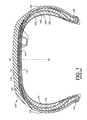
- FIGURE 1 shows a meridional cross section of a prior art pneumatic radial runflat tire 100 similar to that of WO-A1- 00/01544 (cited in the Background section).
- the tire 100 has a tread 110, a belt structure ("belts") 112 comprising one or more belts, a fabric overlay 114 over the belts 112, a fabric underlay 134 under the belts 112 reinforced by high-modulus cords 136 (or “underlay cords” or “reinforcement cords”) that are wound parallel to the equatorial plane (EP) of the tire, and a carcass 116 under the underlay 134.
- belts belt structure
- EP equatorial plane
- the carcass has two inextensible annular beads 120, an inner radial ply 122, an outer radial ply 124 and two sidewalls 126 each reinforced with an inner wedge insert 130 and an outer wedge insert 132 which give the tire 100 a limited runflat capability.
- the underlay 134 stiffens the tread during runflat operation at the expense of stiffening the tread during normal inflation operation.
- the structural reinforcement in the sidewall area of the tire 100 substantially increases the overall thickness of the sidewalls 126 in order to support the tire's load with minimal sidewall deformation in runflat operation.
- Such runflat tire designs provide reasonable, though not ideal, vehicle handling and performance in normal inflated operation and reasonable tire life and vehicle handling in runflat operation.
- Runflat tires generally weigh more than equivalent non-runflat tires because of the additional weight of the reinforcement material in the sidewalls. This problematic additional weight is generally greater in high-profile runflat tires because of the need for larger inserts in the larger sidewalls.
- reinforced sidewalls of a runflat tire should be flexible during normal inflated operation (as flexible as those of a corresponding-sized non-runflat tire), yet rigid during runflat operation.
- this cannot be achieved by conventional wedge inserts, so the stiffness of wedge inserts is designed to be some compromise value in-between, yielding greater than optimum stiffness during normal inflated operation and less than optimum stiffness during runflat operation.
- FIGURE 2 shows a meridional cross-section of a pneumatic radial runflat tire 200 according to the present invention, having a similar construction to that of the prior art runflat tire of FIGURE 1, but with a different type of underlay.
- the tire 200 has a tread 210, a belt structure ("belts") 212 comprising one or more belts, an underlay 234 under the belts 212 reinforced by one or more cords 236 (or “underlay cords” or “reinforcement cords”) that are wound parallel to the equatorial plane (EP) of the tire, and a carcass 216.
- belts belt structure
- cords 236 or "underlay cords” or “reinforcement cords”
- the carcass has two inextensible annular beads 220, one or more plies, such as an inner radial ply 222 and an outer radial ply 224, and two sidewalls 226 each reinforced with one or more wedge inserts, such as an inner wedge insert 230 and an outer wedge insert 232 which contribute to tire rigidity.
- a tire of the present invention can have an overlay, an overlay is not required for this invention nor is it shown in this preferred embodiment.
- the tire 200 is characterized by the underlay reinforcing cords 236 exhibiting dual modulus of elasticity ("modulus") under tension - negligible modulus below a threshold elongation and high modulus above the threshold elongation, and exhibiting a significant, though not necessarily high, modulus under compression.
- modulus dual modulus of elasticity
- the turns of the underlay cord 236 are approximately parallel to the tire's equatorial plane and embedded in a rubber matrix.
- the dual-modulus capability can be achieved in any of a variety of ways.
- the cord can be made of a material that intrinsically has dual-modulus.
- the cord can be made of a higher-modulus strand and a shorter lower-modulus strand in a single sheath.
- US-A-5,419,383 discloses a tire having belt cords with a higher modulus organic strand and a shorter lower modulus organic strand twisted together.
- US-A- 5,558,144 discloses a jointless "band belt", radially outside the "breaker belt”, having an organic low-modulus thread and an organic high-modulus thread twisted together.
- US-A- 4,877,073 discloses an overlay ply having a dual-modulus non-metallic cable comprising two yarns, one yarn not twisted or twisted in a first direction, and the other yarn twisted in the opposite direction, and the cable is twisted in the opposite direction of the twist of the yarn having the larger twist.
- WO-A1 00/69661 having a common assignee with the present invention, discloses a variable-modulus cord, for use in an outermost ply of a runflat tire, comprising a low modulus core material wound with high-modulus cords.
- the underlay 234 has typically 8 to 18 turns of cord 236 per lateral inch (2,54 cm), and the cords are spaced typically 0.35 to 1.50 mm (millimeters) apart.
- the cords 236 have a typically circular or polygonal cross-sectional shape and are typically 0.65 to 1.85 mm in cross-sectional diameter.
- the modulus of each cord 236 is typically less than 5000 MPa below a lower threshold elongation of 0.5-3% (preferably 1-2%), and is typically 80,000 - 210,000 MPa (preferably 90,000-150,000 MPa) above an upper threshold elongation of 1-3%.
- the annular turns of cord 236 are parallel with each other and aligned typically 0 - 5 degrees relative to the equatorial plane.
- the turns of cord 236 are embedded within a green rubber, such as usual breaker coatings.
- the material of the cord 236 can be a polymer or metal or a combination of both.
- a steel wire (monofilament) or cable can exhibit the required dual-modulus characteristic if it is preformed into a non-straight shape (such as coil or zigzag), which exhibits low modulus at low elongation and high modulus when elongated to a straight shape.
- a cord 236 comprised of 3 strands of wire filaments of different moduli twisted together has been found to yield good dual-modulus characteristics for use in the present invention.
- the underlay 234 is installed as a circumferential helically-wound layer between the belts 212 and the green carcass 216. Then, the green carcass 216 is blown up to engage the underlay 234, the belts 212 and the tread 210 to form a completed green tire 200. The resulting green tire 200 is then blown up in the curing mold.
- this embodiment shown in FIGURE 2, has two plies 222,224, it is within the scope of the invention to have more or fewer plies.
- this embodiment has two wedge inserts 230,232 in each sidewall 226, it is within the scope of the invention to have more or fewer wedge inserts.
- the cords 236 of this embodiment exhibit dual modulus, it is within the scope of the invention for the cords 236 to exhibit three or more modulus levels or even a smoothly varying modulus, as long as the cords 236 exhibit negligible modulus in normal inflated mode and high modulus in runflat mode.
- the underlay 234 in this embodiment comprises one continuous cord 236 spirally-wound to form the entire underlay 234, it is within the scope of the invention that the cord 236 be discontinuous (broken in places).
- the underlay 234 in this embodiment is one layer, it may be comprised of multiple radially-overlapping layers, formed from either one long length of ply material or separate lengths of ply material, and the cords of overlapping layers can be oriented overlapping each other (cord-over-cord) or interleaved ("quincunxes"; each cord disposed over the space between two cords in a lower layer) for higher cord stacking density.
- the underlay width may be larger or narrower or of equal width to the breaker package.
- a compound insert may be set between the underlay and the breaker package.
- FIGURE 5 shows an elongate structural beam 500 resting on two supports A and B at its two ends and under flexural (bending) stress from a load L at its center.
- the entire upper portion of the beam 500, including the top flange 572, is under compression, and the lower portion of the beam 500, including the bottom flange 574, is under tension.
- a neutral bending axis 542 is the boundary between the portion under compression and the portion under tension. There is no stress (either compression or tension) along the neutral bending axis 542.
- An elongate structural member, such as the beam 500, is stiffened when either the material of the compression side has increased compressive modulus or the material of the tension side has increased tensile modulus. This principle is used to explain the principle of operation of the present invention, as illustrated in FIGURES 3 and 4.
- FIGURE 3 is a cross-section of the bottom portion of a prior art tire 300 (identical to the prior art tire 100 of FIGURE 1), cut along the tire's equatorial plane, when deflated and being driven in runflat mode. For clarity, only the tread 310, belts 312, overlay 314 and underlay 334 are shown.
- the footprint 344 is the portion of the tread contacting the road surface 340.
- the center of the footprint 344 buckles circumferentially upward, as shown, raising the center of the footprint 344 off the ground. This yields poor steering stability, a swerving ride, flex heating, tread wear and bending fatigue.
- the footprint's inward bow puts the footprint's inner surface 350 under tension and footprint's outer surface 352 under compression, with a neutral bending axis 342 in-between.
- the neutral bending axis 342 can be within the belts 312 near the underlay 334 (as shown) or between the belts 312 and the underlay 334, so compression resistance of the belts contributes little or nothing to tire rigidity.
- the underlay 334 is on the tension side of the neutral bending axis 342 and so does contribute significantly to tire rigidity.
- the portion of the overlay 314 in the footprint region is on the side of the neutral bending axis 342 experiencing compression against which the overlay 314 offers no resistance, because it is only fabric, and hence, the overlay 314 contributes no stiffness in the footprint area.
- the tread 310 bends sharply (buckles outward) under the vehicle's weight.
- the tread's outward bow puts the inner surface 360 under compression and the outer surface 362 under tension, with the neutral bending axis 342 in-between.
- the underlay 334 is on the side of the neutral bending axis 342 experiencing compression against which the underlay 334 offers no resistance, and hence contributes no rigidity to the tire.
- the overlay 314 in this region is on the side of the neutral bending axis 342 experiencing tension against which the overlay 314 offers some resistance, but the overlay 314 contributes negligible rigidity since it is very close to the neutral bending axis 342.
- the footprint 344 In normal inflated mode, the footprint 344 is flat against the road surface 340, so the underlay 334 is under significant stress, though lower than in runflat mode, and so exhibits significant modulus, though lower than in runflat mode, and hence contributes significant rigidity, though lower than in runflat mode, thus yielding an uncomfortably rigid ride. Reducing the stiffness of the underlay cord 336 to soften the normal inflation mode ride will degrade runflat mode rigidity. Stiffening the underlay cord 336 to improve runflat mode rigidity will degrade the softness of the normal inflated mode ride.
- FIGURE 4 is a cross-section of the bottom portion of the tire 400 of the present invention (identical to the prior art tire 200 of FIGURE 2), cut along the tire's equatorial plane, when deflated and being driven in runflat mode. For clarity, only the tread 410, belts 412 and underlay 434 are shown. The footprint 444 is the portion of the tread contacting the road surface 440.
- the cord 436 can be designed to be much stiffer than the prior art cord 336 under high elongation and much more flexible than the prior art cord 336 under low elongation.
- the footprint 444 buckles circumferentially upward, putting the inner side 450 of the tire opposite the footprint 444 under tension and the tire's outer side 452 along the footprint 444 under compression, with a neutral bending axis 442 in-between, approximately along the boundary between the belts 412 and the underlay 434.
- the underlay 434 is in the high tension area, and so exhibits high tensile modulus, and hence stiffens the footprint area.
- the tread's outward bow puts the tread's inner surface 460 under compression and outer surface 462 under tension, with the neutral bending axis 442 in-between.
- the underlay 434 is on the inner, compression, side of the neutral bending axis 442, and so exhibits significant compressive modulus, and hence stiffens the tread 410 on either side of the footprint 444.
- the underlay 434 stiffens the tire 400 both in the footprint area and on either side of the footprint.
- the footprint 444 In normal inflated operation, the footprint 444 is flat against the road surface and the tread on either side of the footprint 444 is not significantly bent, so the underlay 434 is under negligible stress, and so exhibits negligible modulus, and hence does not contribute rigidity, yielding a soft ride.
- the dual-modulus underlay 434 stiffens the tire during runflat operation but not in normal inflated operation. During runflat operation, this extra rigidity better distributes the tire deflection stresses around the tire circumference, reduces rolling resistance, fatigue, wear and heat from flexing, and improves ground contact for a stabler ride. During normal inflated operation, the lack of rigidity yields a softer ride and less damage and heat from flexing. Also, the extra rigidity contributed by the underlay 434 enables employing thinner and/or fewer wedge inserts, thereby reducing weight, cost, and flexural heat.
- a dual-modulus cord 434 between the belts 412 and the carcass 416 simplifies manufacturing, because a dual-modulus cord is easier to stretch around the green carcass when expanding the green carcass against the underlay.
Applications Claiming Priority (2)
| Application Number | Priority Date | Filing Date | Title |
|---|---|---|---|
| US511754 | 2000-02-24 | ||
| US09/511,754 US6371182B1 (en) | 2000-02-24 | 2000-02-24 | Runflat tire with dual-modulus underlay |
Publications (3)
| Publication Number | Publication Date |
|---|---|
| EP1127718A2 true EP1127718A2 (fr) | 2001-08-29 |
| EP1127718A3 EP1127718A3 (fr) | 2003-03-26 |
| EP1127718B1 EP1127718B1 (fr) | 2006-06-28 |
Family
ID=24036296
Family Applications (1)
| Application Number | Title | Priority Date | Filing Date |
|---|---|---|---|
| EP01103382A Expired - Lifetime EP1127718B1 (fr) | 2000-02-24 | 2001-02-13 | Pneumatique adapté au roulage à plat ayant une sous couche à double module |
Country Status (5)
| Country | Link |
|---|---|
| US (1) | US6371182B1 (fr) |
| EP (1) | EP1127718B1 (fr) |
| JP (1) | JP2001246912A (fr) |
| BR (1) | BR0100528A (fr) |
| DE (1) | DE60121072T2 (fr) |
Cited By (2)
| Publication number | Priority date | Publication date | Assignee | Title |
|---|---|---|---|---|
| EP1270270A1 (fr) * | 2001-06-29 | 2003-01-02 | Sumitomo Rubber Industries Ltd. | Bandage pneumatique |
| EP1676730A1 (fr) * | 2004-12-31 | 2006-07-05 | Societe de Technologie Michelin STM | Pneumatique à mobilité étendue avec des nappes de carcasse séparées dans le sommet |
Families Citing this family (6)
| Publication number | Priority date | Publication date | Assignee | Title |
|---|---|---|---|---|
| US6622764B2 (en) * | 2002-02-01 | 2003-09-23 | The Goodyear Tire & Rubber Company | Underlay structure for increased crown stiffening |
| WO2004002755A1 (fr) * | 2002-06-28 | 2004-01-08 | Bridgestone Corporation | Pneumatique gonflable |
| KR101034440B1 (ko) | 2003-07-31 | 2011-05-12 | 한국타이어 주식회사 | 자동차용 공기입 타이어 |
| JP2005161998A (ja) * | 2003-12-02 | 2005-06-23 | Bridgestone Corp | 空気入りタイヤ |
| US8652116B2 (en) * | 2005-09-30 | 2014-02-18 | The Procter & Gamble Company | Preferential bend structure and articles containing said structure |
| MX2011006013A (es) * | 2008-12-19 | 2011-06-28 | Michelin Rech Tech | Desempeño mejorado de hidroplaneo para una llanta. |
Citations (5)
| Publication number | Priority date | Publication date | Assignee | Title |
|---|---|---|---|---|
| WO1980000069A1 (fr) * | 1978-06-16 | 1980-01-24 | Goodyear Tire & Rubber | Cordon composite de renforcement pour renforcer les articles elastomeres |
| DE4135599A1 (de) * | 1991-10-29 | 1993-05-06 | Continental Aktiengesellschaft, 3000 Hannover, De | Fahrzeugluftreifen |
| WO1998054014A1 (fr) * | 1997-05-29 | 1998-12-03 | The Goodyear Tire & Rubber Company | Pneumatique pouvant rouler a plat avec tenue amelioree a l'etat non gonfle |
| WO1999048710A1 (fr) * | 1998-03-26 | 1999-09-30 | The Goodyear Tire & Rubber Company | Sous-couche en tissu et renfort de bande de roulement pour ameliorer la rigidite de la bande de roulement d'un pneu a affaissement limite |
| WO2000001544A1 (fr) * | 1998-07-07 | 2000-01-13 | The Goodyear Tire & Rubber Company | Toile sous-jacente visant a renforcer la rigidite meridienne et circonferentielle de la bande de roulement |
Family Cites Families (10)
| Publication number | Priority date | Publication date | Assignee | Title |
|---|---|---|---|---|
| US4059138A (en) | 1972-08-11 | 1977-11-22 | Uniroyal, S.A. | Run-flat tire and hub therefor |
| US4111249A (en) | 1976-11-08 | 1978-09-05 | Grumman Aerospace Corporation | Band reinforced radial tire |
| US4428411A (en) | 1982-08-23 | 1984-01-31 | Grumman Aerospace Corporation | Run-flat tire and method of making same |
| US4459167A (en) | 1982-08-23 | 1984-07-10 | Grumman Aerospace Corporation | Run-flat tire and method of making same |
| US4456048A (en) | 1983-01-24 | 1984-06-26 | Grumman Aerospace Corporation | Dual-modulus band banded tire |
| US5054532A (en) * | 1989-02-06 | 1991-10-08 | Bridgestone Corporation | Pneumatic tires with wavy or zigzag cord ply between belt and carcass |
| JPH0750494A (ja) * | 1993-08-06 | 1995-02-21 | Mitsubishi Electric Corp | 冷却装置 |
| US5427166A (en) * | 1994-01-18 | 1995-06-27 | Michelin Recherche Et Technique S.A. | Run-flat tire with three carcass layers |
| FR2754769B1 (fr) * | 1996-10-23 | 1998-12-11 | Michelin & Cie | Armature de sommet pour pneumatique "poids-lourds" de rapport de forme < 0,60 |
| US5871600A (en) * | 1997-05-29 | 1999-02-16 | The Goodyear Tire & Rubber Company | Runflat tire with different modulus or elongation carcass cords |
-
2000
- 2000-02-24 US US09/511,754 patent/US6371182B1/en not_active Expired - Lifetime
-
2001
- 2001-02-13 EP EP01103382A patent/EP1127718B1/fr not_active Expired - Lifetime
- 2001-02-13 DE DE60121072T patent/DE60121072T2/de not_active Expired - Fee Related
- 2001-02-13 BR BR0100528-6A patent/BR0100528A/pt active Search and Examination
- 2001-02-16 JP JP2001039468A patent/JP2001246912A/ja active Pending
Patent Citations (5)
| Publication number | Priority date | Publication date | Assignee | Title |
|---|---|---|---|---|
| WO1980000069A1 (fr) * | 1978-06-16 | 1980-01-24 | Goodyear Tire & Rubber | Cordon composite de renforcement pour renforcer les articles elastomeres |
| DE4135599A1 (de) * | 1991-10-29 | 1993-05-06 | Continental Aktiengesellschaft, 3000 Hannover, De | Fahrzeugluftreifen |
| WO1998054014A1 (fr) * | 1997-05-29 | 1998-12-03 | The Goodyear Tire & Rubber Company | Pneumatique pouvant rouler a plat avec tenue amelioree a l'etat non gonfle |
| WO1999048710A1 (fr) * | 1998-03-26 | 1999-09-30 | The Goodyear Tire & Rubber Company | Sous-couche en tissu et renfort de bande de roulement pour ameliorer la rigidite de la bande de roulement d'un pneu a affaissement limite |
| WO2000001544A1 (fr) * | 1998-07-07 | 2000-01-13 | The Goodyear Tire & Rubber Company | Toile sous-jacente visant a renforcer la rigidite meridienne et circonferentielle de la bande de roulement |
Cited By (4)
| Publication number | Priority date | Publication date | Assignee | Title |
|---|---|---|---|---|
| EP1270270A1 (fr) * | 2001-06-29 | 2003-01-02 | Sumitomo Rubber Industries Ltd. | Bandage pneumatique |
| US6926053B2 (en) | 2001-06-29 | 2005-08-09 | Sumitomo Rubber Industries, Ltd. | Pneumatic tire variable elasticity modules metallic band cord |
| EP1676730A1 (fr) * | 2004-12-31 | 2006-07-05 | Societe de Technologie Michelin STM | Pneumatique à mobilité étendue avec des nappes de carcasse séparées dans le sommet |
| WO2006069649A1 (fr) * | 2004-12-31 | 2006-07-06 | Societe De Technologie Michelin | Pneu a mobilite accrue aux portions de carcasse separees au sommet |
Also Published As
| Publication number | Publication date |
|---|---|
| EP1127718B1 (fr) | 2006-06-28 |
| BR0100528A (pt) | 2001-10-09 |
| US6371182B1 (en) | 2002-04-16 |
| JP2001246912A (ja) | 2001-09-11 |
| EP1127718A3 (fr) | 2003-03-26 |
| DE60121072D1 (de) | 2006-08-10 |
| DE60121072T2 (de) | 2006-12-28 |
Similar Documents
| Publication | Publication Date | Title |
|---|---|---|
| EP0984867B1 (fr) | Pneumatique pouvant rouler degonfle, inextensible et resistant aux temperatures elevees | |
| JP5284307B2 (ja) | クラウン強化のためのアンダーレイ構造 | |
| US6659148B1 (en) | Bead reinforcing structure for radial truck tires | |
| US6938659B2 (en) | Runflat tire having crown-reinforcing insert extending into the sidewalls | |
| US6719029B2 (en) | Tire wall gauges to optimize runflat tire ride comfort | |
| EP1242256B1 (fr) | Elements d'insertion en coin a rigidite variable pour pneus a affaissement limite | |
| EP1127718B1 (fr) | Pneumatique adapté au roulage à plat ayant une sous couche à double module | |
| KR20020060246A (ko) | 확장된 이동성을 가진 타이어 비드 | |
| EP1097048B1 (fr) | Moyen de renforcement de la bande de roulement pour pneumatique a mobilite accrue | |
| EP1181161B1 (fr) | Structure d'inserts profiles renforces pour pneus a mobilite accrue | |
| JP2021095124A (ja) | タイヤのベルト構造 | |
| US7104301B2 (en) | Discontinuous ply for runflat tire construction | |
| US6561245B1 (en) | Thread reinforcement means for extended mobility tire | |
| US6763866B1 (en) | Reinforced wedge-insert construction for extended mobility tires | |
| EP1094955B1 (fr) | Flanc ameliore avec piece apportee pour pneumatique a affaissement limite | |
| US6631748B1 (en) | Sidewall with insert construction for runflat tire | |
| EP1156937B1 (fr) | Ceinture discontinue pour structure de pneu a affaissement limite | |
| US6814120B1 (en) | Fabric support for metal reinforced inner ply of runflat tire | |
| EP3176005A1 (fr) | Construction mono-courroie bidirectionnelle pour un pneumatique | |
| WO2000020236A1 (fr) | Structure amelioree pour pneu pouvant rouler a plat | |
| WO2000032424A1 (fr) | Structure de renforcement du talon d'un pneumatique radial de camion | |
| JP2020200032A (ja) | ラジアルタイヤ |
Legal Events
| Date | Code | Title | Description |
|---|---|---|---|
| PUAI | Public reference made under article 153(3) epc to a published international application that has entered the european phase |
Free format text: ORIGINAL CODE: 0009012 |
|
| AK | Designated contracting states |
Kind code of ref document: A2 Designated state(s): AT BE CH CY DE DK ES FI FR GB GR IE IT LI LU MC NL PT SE TR |
|
| AX | Request for extension of the european patent |
Free format text: AL;LT;LV;MK;RO;SI |
|
| PUAL | Search report despatched |
Free format text: ORIGINAL CODE: 0009013 |
|
| AK | Designated contracting states |
Designated state(s): AT BE CH CY DE DK ES FI FR GB GR IE IT LI LU MC NL PT SE TR Kind code of ref document: A3 Designated state(s): AT BE CH CY DE DK ES FI FR GB GR IE IT LI LU MC NL PT SE TR |
|
| AX | Request for extension of the european patent |
Extension state: AL LT LV MK RO SI |
|
| RIC1 | Information provided on ipc code assigned before grant |
Ipc: 7B 60C 17/00 A Ipc: 7B 60C 9/22 B |
|
| 17P | Request for examination filed |
Effective date: 20030926 |
|
| 17Q | First examination report despatched |
Effective date: 20031104 |
|
| AKX | Designation fees paid |
Designated state(s): DE FR GB IT |
|
| GRAP | Despatch of communication of intention to grant a patent |
Free format text: ORIGINAL CODE: EPIDOSNIGR1 |
|
| GRAS | Grant fee paid |
Free format text: ORIGINAL CODE: EPIDOSNIGR3 |
|
| GRAA | (expected) grant |
Free format text: ORIGINAL CODE: 0009210 |
|
| RIN1 | Information on inventor provided before grant (corrected) |
Inventor name: NGUYEN, GIA VAN Inventor name: COLANTONIO, LAURENT Inventor name: ROESGEN, ALAIN EMILE FRANCOIS Inventor name: PHILPOTT, FRANK |
|
| AK | Designated contracting states |
Kind code of ref document: B1 Designated state(s): DE FR GB IT |
|
| PG25 | Lapsed in a contracting state [announced via postgrant information from national office to epo] |
Ref country code: IT Free format text: LAPSE BECAUSE OF FAILURE TO SUBMIT A TRANSLATION OF THE DESCRIPTION OR TO PAY THE FEE WITHIN THE PRESCRIBED TIME-LIMIT;WARNING: LAPSES OF ITALIAN PATENTS WITH EFFECTIVE DATE BEFORE 2007 MAY HAVE OCCURRED AT ANY TIME BEFORE 2007. THE CORRECT EFFECTIVE DATE MAY BE DIFFERENT FROM THE ONE RECORDED. Effective date: 20060628 |
|
| REG | Reference to a national code |
Ref country code: GB Ref legal event code: FG4D |
|
| REF | Corresponds to: |
Ref document number: 60121072 Country of ref document: DE Date of ref document: 20060810 Kind code of ref document: P |
|
| ET | Fr: translation filed | ||
| PGFP | Annual fee paid to national office [announced via postgrant information from national office to epo] |
Ref country code: GB Payment date: 20070105 Year of fee payment: 7 |
|
| PGFP | Annual fee paid to national office [announced via postgrant information from national office to epo] |
Ref country code: DE Payment date: 20070228 Year of fee payment: 7 |
|
| PLBE | No opposition filed within time limit |
Free format text: ORIGINAL CODE: 0009261 |
|
| STAA | Information on the status of an ep patent application or granted ep patent |
Free format text: STATUS: NO OPPOSITION FILED WITHIN TIME LIMIT |
|
| 26N | No opposition filed |
Effective date: 20070329 |
|
| PGFP | Annual fee paid to national office [announced via postgrant information from national office to epo] |
Ref country code: IT Payment date: 20070526 Year of fee payment: 7 |
|
| PGFP | Annual fee paid to national office [announced via postgrant information from national office to epo] |
Ref country code: FR Payment date: 20070201 Year of fee payment: 7 |
|
| GBPC | Gb: european patent ceased through non-payment of renewal fee |
Effective date: 20080213 |
|
| REG | Reference to a national code |
Ref country code: FR Ref legal event code: ST Effective date: 20081031 |
|
| PG25 | Lapsed in a contracting state [announced via postgrant information from national office to epo] |
Ref country code: DE Free format text: LAPSE BECAUSE OF NON-PAYMENT OF DUE FEES Effective date: 20080902 |
|
| PG25 | Lapsed in a contracting state [announced via postgrant information from national office to epo] |
Ref country code: FR Free format text: LAPSE BECAUSE OF NON-PAYMENT OF DUE FEES Effective date: 20080229 |
|
| PG25 | Lapsed in a contracting state [announced via postgrant information from national office to epo] |
Ref country code: GB Free format text: LAPSE BECAUSE OF NON-PAYMENT OF DUE FEES Effective date: 20080213 |
|
| PG25 | Lapsed in a contracting state [announced via postgrant information from national office to epo] |
Ref country code: IT Free format text: LAPSE BECAUSE OF NON-PAYMENT OF DUE FEES Effective date: 20080213 |