EP1127684A2 - Slide driving apparatus of press machine - Google Patents
Slide driving apparatus of press machine Download PDFInfo
- Publication number
- EP1127684A2 EP1127684A2 EP01301619A EP01301619A EP1127684A2 EP 1127684 A2 EP1127684 A2 EP 1127684A2 EP 01301619 A EP01301619 A EP 01301619A EP 01301619 A EP01301619 A EP 01301619A EP 1127684 A2 EP1127684 A2 EP 1127684A2
- Authority
- EP
- European Patent Office
- Prior art keywords
- slide
- link
- links
- upper toggle
- driving device
- Prior art date
- Legal status (The legal status is an assumption and is not a legal conclusion. Google has not performed a legal analysis and makes no representation as to the accuracy of the status listed.)
- Granted
Links
- 230000033001 locomotion Effects 0.000 claims abstract description 19
- 238000006073 displacement reaction Methods 0.000 claims description 41
- 238000010276 construction Methods 0.000 abstract description 12
- 230000007246 mechanism Effects 0.000 abstract description 9
- 230000003044 adaptive effect Effects 0.000 abstract 1
- 238000012986 modification Methods 0.000 description 3
- 230000004048 modification Effects 0.000 description 3
- 230000000694 effects Effects 0.000 description 2
- 125000004122 cyclic group Chemical group 0.000 description 1
- 238000010586 diagram Methods 0.000 description 1
- 239000007787 solid Substances 0.000 description 1
Images


Classifications
-
- B—PERFORMING OPERATIONS; TRANSPORTING
- B30—PRESSES
- B30B—PRESSES IN GENERAL
- B30B1/00—Presses, using a press ram, characterised by the features of the drive therefor, pressure being transmitted directly, or through simple thrust or tension members only, to the press ram or platen
- B30B1/10—Presses, using a press ram, characterised by the features of the drive therefor, pressure being transmitted directly, or through simple thrust or tension members only, to the press ram or platen by toggle mechanism
- B30B1/14—Presses, using a press ram, characterised by the features of the drive therefor, pressure being transmitted directly, or through simple thrust or tension members only, to the press ram or platen by toggle mechanism operated by cams, eccentrics, or cranks
-
- B—PERFORMING OPERATIONS; TRANSPORTING
- B30—PRESSES
- B30B—PRESSES IN GENERAL
- B30B15/00—Details of, or accessories for, presses; Auxiliary measures in connection with pressing
- B30B15/0064—Counterbalancing means for movable press elements
Definitions
- the present invention relates to machine tool presses and in particular concerns a slide driving device driven by a toggle link mechanism in a machine tool press.
- the present invention also relates to a slide driving device that is small and efficiently operates at high speed in a two point press machine.
- Japanese Laid-Open Patent Number 8-118082 is an example of a press machine in the related art.
- the press machine has a simplified construction.
- the press machine has adjustable speed. Further, fluctuation of a bottom dead center position, due to an inertial force of a slide, is minimized.
- an aspect of the present invention relates to a slide driving device for a press machine driven by a first and second upper toggle link mechanisms pivotably mounted above a slide.
- the upper toggle links include first links connected at a connecting link on a common tangent line.
- the connecting link is driven by a connecting rod receiving eccentric movement from a crank shaft.
- the upper toggle links also include second links each connected to lower toggle links.
- the lower toggle links operate a plunger to drive a slide.
- Alternative arrangements allow multiple positions of the upper toggle links and crank shaft along with multiple lengths for the first and second links.
- a dynamic balancer may be added to the upper toggle links to minimize vibration. Together, these arrangements provide a slide driving device with minimized vibration and simplified construction.
- the parallelism of the slide can be maintained by only having one connecting link to connect between first support point pins of the left and right hand side upper toggle links.
- a slide driving device comprising: at least first and second upper toggle means, a rotation center on each of the first and second upper toggle means, each of the first and second upper toggle means rotatable in an arc, a first point pin on each first and second upper toggle means, a first link connects each rotation center to each respective first point pin, a connecting link connects the first and second upper toggle means at the first point pins on a common inner tangent line to each arc where the first links are parallel, the connecting link transfers a guiding displacement to the first and second upper toggle means, a first and second plunger drive a slide in a displacement cycle, the first and second plungers operably connect to the first and second upper toggle means, and the first and second upper toggle means transfer the guiding displacement to the plungers and the slide operates through the displacement cycle whereby the slide driving device operates
- a slide driving device further comprising: a crank shaft having at least a first eccentric part, the first eccentric part having an eccentric displacement, a connecting rod connects the first eccentric part to the connecting link, and the connecting rod operably transfers the eccentric displacement to the connecting link whereby the slide operates through the displacement cycle.
- a slide driving device further comprising: a second point pin on each the first and second upper toggle means, a second link connects each of the rotation center to each respective second point pin, at least first and second lower toggle links, the first and second lower toggle links operably connected to respective first and second plungers, and the first and second upper toggle means operably transfer the guiding displacement through respective the second links to respective the first and second lower toggle links and the first slide whereby the slide operates through the displacement cycle.
- a slide driving device further comprising: a first balancer on the first upper toggle means, a second balancer on the second upper toggle means, each first and second balancer has a weight and a shape adaptable to each respective first link, a third link connects each rotation center to each respective, the first and second balancer, each third link being positioned relative to each second link, and each first and second balancers positioned to minimize vibration in the slide driving device when the first and second plungers drive the slide in the displacement cycle, whereby the operating vibration of the slide driving device is minimized.
- a slide driving device wherein: the first upper toggle means is a first upper toggle element, the second upper toggle means is a second upper toggle element, and the first and second upper toggle elements operable to transfer the guiding displacement from the connecting link to each respective second link, whereby the slide operates through the displacement cycle.
- a slide driving device wherein the first, second, and third links have a similar length, the arc for each respective first and second upper toggle means has a similar radius, each rotation center above each respective plunger, each rotation center an equidistant from a common center line between the first and second upper toggle means, the crank shaft below the connection rod, and the second support pins and the first and second lower toggle links operable on first outer sides of each respective the plunger, whereby the slide operates through the displacement cycle.
- a slide driving device wherein: the first, second, and third links have the same length, the arc for each respective first and second upper toggle means has the same radius, each rotation center above each respective plunger, each rotation center equidistant from a common center line between the first and second upper toggle means, the crank shaft below the connection rod, and the second support pins and the first and second lower toggle links operable on an inner side of each respective plunger, whereby the slide operates through the displacement cycle.
- a slide driving device wherein: the first, second, and third links have the same length, the arc for each respective first and second upper toggle means has the same radius, each rotation center above each plunger, each rotation center an equal distance from a common center line between the first and second upper toggle means, the crank shaft above the connection rod, and the second support pins and the first and second lower toggle links operable on an inner side of each respective plunger, whereby the slide operates through the displacement cycle.
- a slide driving device wherein: each rotation center is a first distance from a common center line between the first and second upper toggle means, each plunger is a second distance from the common center line, the first distance greater than the second distance, each first link longer than the second link, each second point pin operable substantially above each respective plunger and respective to the toggle link, the crank shaft above the connection rod along the common center line, and each lower toggle link and each respective plunger being substantially unitary and operable parallel to the common center line, whereby the slide operates through the displacement cycle with reduced vibration.
- a slide driving device wherein: the rotation center is a first rotation center for the first upper toggle means, the rotation center is a second rotation center for the second upper toggle means, the first rotation center and the second rotation center at different distances above each respective plunger, the first point pins substantially tangent the common center line, and the connecting rod and the connecting link operate substantially along the common center line and minimize vibration in the slide driving device when the first and second plungers drive the slide in the displacement cycle.
- a slide driving device comprising: first and second upper toggle elements, the first and second upper toggle elements equidistant from a common center line, the first and second upper toggle elements operable in first and second arcs, the first and second upper toggle elements joined by connecting link at an inner tangent line to the first and second arcs, first and second lower toggle elements, the first and second lower toggle elements operably joined to each respective first and second upper toggle elements, the first and second lower toggle elements drive a slide element in a displacement cycle, the common connecting link receiving a driving displacement; and the first and second upper toggle elements transmit the driving displacement to the first and second lower toggle elements, and the first and second lower toggle elements drive the slide element in the displacement cycle whereby vibration is minimized.
- a slide driving device for a press machine comprising: a left and a right upper toggle link each pivotably mounted onto respective fixed support point pins, the fixed support point pins equidistant from a center line between, a first support link on the left and right upper toggle links, each first support link operable in an arc, each the first support link having an equal length, a connecting link connects each the first support links along a common inner tangent line to each the arc where the first support links are parallel to each other, a connecting rod connects the connecting link to an eccentric part of a crank shaft, first and second lower toggle links connect second support point pins of the left and right upper toggle links along a second link of each the left and right upper toggle link, the second links rotatably connect the left and right lower toggle links with left and right points on a slide, and the connecting rod transmits a guiding displacement to the left and right upper toggle links, through the lower toggle links, to the slide to drive the slide through a displacement
- a slide driving device for a press machine further comprising: a dynamic balancer are mounted to an outer end of each the left and right upper toggle links along a third link, and each the dynamic balancer has a weight and a shape selected to minimize vibration of the slide driving device.
- a slide driving device for a press machine further comprising: a left and right plunger upright at left and right points of the slide, first ends of the left and right plungers operably connect with the left and right lower toggle links, the left and right fixed support points horizontally equidistant from the center line above respective to the left and right plungers, the second support point pins are placed on outer sides of each of the left and right plunger, and the crank shaft is below the connecting link.
- a slide driving device for a press machine further comprising: left and right plungers provided upright at left and right points of the slide, first ends of each the left and right plungers connect to respective left and right lower toggle links, the left and right fixed support points equidistant from the common center line above each respective of the left and right plunger, the second support point pins placed on inner sides of each respective left and right plunger, and the crank shaft below the connecting link.
- a slide driving device for a press machine further comprising: left and right plungers upright at left and right points of the slide, ends of each the left and right plunger connect with each respective left and right lower toggle link, the left and right fixed support points equidistant from the center line and outward from directly above the plungers, the second support point pins on inner sides of each respective left and right plunger, and the crank shaft is placed above the connecting link.
- a slide driving device for a press machine further comprising: left and right plungers upright at left and right points of the slide, ends of each the left and right plunger connect with each respective left and right lower toggle link, the left and right fixed support points at first and second positions, the first and second positions above each the left and right plunger at different heights, the second support point pins on outer sides of each respective the left and right plungers, and the crank shaft is placed below the connecting link.
- a slide driving device for a press machine further comprising: the left and right fixed support points horizontally equidistant from the center line outward from each the left and right points of the slide, the second links perpendicular to the center line when each respective second support point pin is directly above each respective left and right points on the slide, and the crank shaft is above the connecting link.
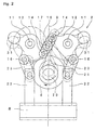
- a press machine 1 including a slide driving device 2 mounted to a frame 3.
- the slide driving device 2 operates a slide 8 through a pair of plungers 22
- the motion of the slide driving device 2 and slide 8 are shown as solid and two-dashed lines.
- the solid line indicates when slide driving device 2 is at a top dead center, position and the two-dashed line indicates when slide driving device 2 is at a bottom dead center position.
- a motor 4 rests on frame 3 of press machine 1.
- a belt 5 attaches the motor 4 to a fly wheel 6.
- the belt 5, transmits power from motor 4 to the fly wheel 6 through a disconnecting clutch (not shown).
- the fly wheel 6 rotates on a driving shaft (not shown).
- a bolster 7 is fixed to the frame 3 below the slide 8 (as shown to the bottom of Figure 1).
- the slide 8 can be raised and lowered relative to the bolster 7.
- an upper mold and a lower mold are mounted on the slide 8 and bolster 7, respectively.
- the slide 8 and plungers 22 are both guided by guide devices(not shown) relative.to the bolster 7.
- a pair of fixed support point pins 11 are fixed on the respective left and right hand side positions on an upper part of the frame 3 (shown to the left and right of the drawing in Figure 1).
- the fixed support point pins 11 are equidistant from a vertical plane 9.
- the fixed support point pins 11 are also on the same horizontal plane.
- the vertical plane 9 is in the center of the left and right positions. It is to be understood, that the vertical plane 9 is at a representational center position of the slide driving device 2. It is to be further understood, that vertical surface 9 allows a positional component comparison to be made throughout the operation of slide driving device 2.
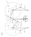
- An upper toggle link 12 is pivotably mounted on each of the fixed support point pins 11.
- the upper toggle links 12 each include three fixed links at predetermined first, second, and third positions which are substantially equidistant from the respective fixed support point pins 11.
- a first support point pin 14 is provided at the first position on each upper toggle link 12
- a second support point pin 16 is provided at the second position on each upper toggle link 12
- a dynamic balancer 31 is provided at the third position on each upper toggle link 12.
- the dynamic balancer 31 includes a weight portion (not shown) that corresponds to a weight of the first link 13 portion of each upper toggle link 12.
- the weight of the dynamic balancer 31 is selected and positioned to dampen operating vibration by countering the forces, effects, and motions of the slide 8.
- the distance from the fixed support point pin 11 to the first support point pin 14 is the same as the distance from the fixed support pin 11 to the second support point pin 16.
- a first link 13 is defined between the fixed support point pin 11 and the first support point pin 14
- a second link 15 is defined between the fixed support point pin 11 and the second support point pin 16.
- a third link 30 is defined between the support point pin 11 and dynamic balancer 31. The third link 30 is perpendicular to the second link 15 and extends in a direction away from the vertical plane 9.
- first support point pins 14, second support point pins 16, and dynamic balancers 31 move along a pair of circular arcs 10, of an equal radius (shown by dashed lines).
- the fixed support point pins 11 are the centers of circular arcs 10.
- the left and right hand side first support point pins 14 When the left and right hand side first support point pins 14 are both positioned at tangent points on a common tangent line 19 of the circular arcs 10 (shown by the dashed line), the left and right hand side first links 13 are parallel to each other.
- a connecting link 17 connects the first links 13 in this position at first support point pins 14. At this position, the connecting link 17 is at a pitch of the distance between left and right first support point pins 14.
- a center support point pin 18 is provided at a midpoint along the connecting link 17.
- the first links 13 swing along circular arcs 10 and the center support point pin 18 has an approximate linear motion along the inner tangent line 29 due to the Watt-link-type mechanism so defined.
- the present invention takes advantage of the fact that the pivot swinging angles for each of the left and right hand side first links 13 are approximately equal at that time.
- a connecting rod 21 extends from the center support point pin 18.
- the connecting rod 21 has a large end and a small end.
- the small end of connecting rod 21 is rotatably connected to the center support point pin 18.
- the large end of the connecting rod 21 is rotatably connected to an eccentric part (not shown) of a crank shaft 20.
- the crank shaft 20 includes a shaft core (not shown) positioned in a front-back direction of the press machine in a line perpendicular to the plane of the drawing of Figure 1.
- the plungers 22 extend from respective left and right hand side points on the slide 8, toward respective fixed support point pins 11. Each plunger 22 has an upper end positioned directly below the fixed support point pins 11.
- the second support point pins 16 of the second links 15 rotatably connected the upper ends of the plungers 22 through a pair of lower toggle links 23.
- the lower toggle links 23 have equal lengths.
- the second support pins 16 operate on an outside portion of plungers 22, distant from the vertical plane 9.
- crank shaft 20 As the crank shaft 20 rotates, the eccentric part of the crank transmits motion to the large end of connecting rod 21.
- the driving motion of the connecting rod 21 transmits the motion to the center support point pin 18 through the small end of connecting rod 21 so that the upper links 12 pivot about their respective axes.
- Crank shaft 20 rotates through a complete circle of 360 degrees (the crank angle) relative to the vertical plane 9.
- the crank shaft 20, connects to the fly wheel 6 through the disconnecting clutch.
- crank shaft 20 rotates in the direction of the arrow shown in Figure 1 and Figure 2, the eccentric part of the crank drives the connecting rod 21 in an up-down reciprocal motion.
- connecting rod 21 moves, the connecting link 17 moves the upper toggle links 12 through the respective first support point pins 14.
- slide 8 is at a bottom dead center position relative to the bolster 7. It should be understood that a top dead position is defined opposite the bottom dead center position, at substantially 0 or 360 crank angle degrees.
- slide 8 is at the bottom dead center position once during each cycle.
- Fig. 5 showing a second embodiment of the slide driving device 2.
- the slide 8 On the right hand side of the drawing in Fig. 5, the slide 8 is at the top dead center position.
- slide 8 On the left hand side of the drawing in Fig. 5, slide 8 is at the bottom dead center position.
- second support point pins 16 operate on the inward side of plungers 22 relative to the vertical plane 9.
- dynamic balancers 31 may additionally have a shape or weight adapted to compensate for the operating forces in this second embodiment.
- FIG. 6 shows a third embodiment of the slide driving device 2.
- the right hand side portion of the drawing in Figure 6 shows the slide 8 at the top dead position and the left hand side portion of the drawing shows the slide 8 at the bottom dead center position.
- crank shaft 20, fly wheel 6, and connecting rod 21 are positioned above the center support point 18 the and connecting link 17.
- FIG. 7 showing a fourth embodiment of slide driving device 2 and press machine 1. Again, the right portion of the figure shows slide 8 at the top dead center position, and the left portion of the figure shows slide 8 at the bottom dead center position.
- the positions of the fixed support point pins 11 are at different relative heights.
- the plungers 22 have different respective lengths to position the slide 8 horizontally with respect to the bolster 7.
- the connecting link 17 moves substantially vertically, along the vertical plane 9 such that the side-to-side swinging movement of the connecting rod 21 is minimized. Since the swinging movement of the connecting rod 21 is minimized one vibration source is minimized.
- FIG. 8 shows a fifth embodiment of the slide driving device 2 according to the present invention.
- the right hand side portion of the drawing shows slide 8 at the top dead center position
- the left hand side portion of the drawing shows slide 8 at the bottom dead center position.
- crank shaft 20, fly wheel 6, and connecting rod 21 are positioned above the center support point pin 18.
- the fixed support point pins 11 are positioned horizontally distant from and vertically above plungers 22.
- the second links 15 are positioned relative to plungers 22 such that the second support point pins 16 are substantially directly above the plungers 22 during operation.
- second support point pins 16 move generally vertically relative to plungers 22 and lower toggle links 23 are made unitary with plungers 22. It is to be understood, that due to the minimal horizontal movement of second support points 16, the plungers may be rotatably fixed to the second support points 16, thereby simplifying construction.
- connecting rod 21 connects with center support point pin 18 at a midpoint of connecting link 17
- the invention may also be implemented by connecting along either side of connecting link 17 or either upper toggle link 12.
- the parallelism of slide driving device 2 may be maintained.
- the parallelism is maintained by connecting first support point pins 14 of each upper toggle link 12 through a single connecting link. Since the single connecting link involves pin-type connections (or similar simplified connections), construction is simplified and high precision in construction is achievable.
- press machine 1 may be simply constructed with smaller parts, thus reducing construction time and cost.
- crank shaft 20 may be positioned near the center of press machine 1, thus reducing the total height of press machine 1, increasing operational stability, and allowing narrower or wider spacing between plungers 22 according to customer need.
- crank shaft 20 may be positioned above upper toggle links 12, thus allowing a shorter length for plungers 22, simplifying movement, and maintaining operational parallelism.
- the distance between upper toggle links 12 may be increased so that the swing angle of second links15 is small compared to the swing angle of first links 13. Since the second support point pins 16 move substantially vertically, plungers 22 may be made unitary with lower toggle links 23. As a result, parallelism is easily maintained and the connecting parts may be simplified thus reducing costs and allowing increased precision.
- a nail and screw may not be structural equivalents in that a nail relies entirely on friction between a wooden part and a cylindrical surface whereas a screw's helical surface positively engages the wooden part, in the environment of fastening wooden parts, a nail and a screw may be equivalent structures.
Abstract
Description
- The present invention relates to machine tool presses and in particular concerns a slide driving device driven by a toggle link mechanism in a machine tool press. The present invention also relates to a slide driving device that is small and efficiently operates at high speed in a two point press machine.
- Japanese Laid-Open Patent Number 8-118082 is an example of a press machine in the related art. The press machine has a simplified construction. The press machine has adjustable speed. Further, fluctuation of a bottom dead center position, due to an inertial force of a slide, is minimized.
- However in the above example, to maintain the parallelism of the slide, ball bearings are needed on both ends of a link pin. The ball bearings necessitate linear guide grooves to guide the ball bearings in operation. The clearance of the ball bearings and the guide grooves affects the parallelism of the slide. Further, with a three dimensional configuration, the lateral balance of the press machine is complicated. Such a design requires three connecting rods arranged in a left- right horizontal direction. The three connecting rods require three locations for eccentric parts on an operating crank shaft, thereby increasing complexity.
- There is a requirement to provide a slide driving device for a press machine.
- There is another requirement to provide a slide driving device where the construction has a minimum number of parts and high precision is easily obtained.
- There is a further requirement to provide a two point press machine driven by a simple toggle link mechanism.
- There is another requirement to provide a sliding device for a press machine where a toggle link mechanism is bent in a left-right direction.
- There is a yet further requirement to provide a press machine where the parallelism of the slide can be easily maintained.
- There is also a requirement to provide a press machine where the vibration of operation may be substantially suppressed.
- There is a further requirement to provide a press machine where the motion of a connecting rod is minimized.
- There is another requirement to provide a press machine where the construction and height may be adjusted to maximize stability and minimize the spacing between multiple plungers.
- Briefly stated an aspect of the present invention relates to a slide driving device for a press machine driven by a first and second upper toggle link mechanisms pivotably mounted above a slide. The upper toggle links include first links connected at a connecting link on a common tangent line. The connecting link is driven by a connecting rod receiving eccentric movement from a crank shaft. The upper toggle links also include second links each connected to lower toggle links. The lower toggle links operate a plunger to drive a slide. Alternative arrangements allow multiple positions of the upper toggle links and crank shaft along with multiple lengths for the first and second links. A dynamic balancer may be added to the upper toggle links to minimize vibration.
Together, these arrangements provide a slide driving device with minimized vibration and simplified construction. - In an aspect of this invention, by forming a modified type of Watt-link mechanism on the left and right hand driving branching parts, the parallelism of the slide can be maintained by only having one connecting link to connect between first support point pins of the left and right hand side upper toggle links. In addition, there only needs to be one connecting rod, and ball bearings and guide grooves are unnecessary. Because there are only pin connections between the links, there are very few construction parts, and high precision is easily achieved.
- According to an aspect of the present invention, there is provided:
- A slide driving device comprising: at least first and second upper toggle means, a rotation center on each of the first and second upper toggle means, each of the first and second upper toggle means rotatable in an arc, a first point pin on each first and second upper toggle means, a first link connects each rotation center to each respective first point pin, a connecting link connects the first and second upper toggle means at the first point pins on a common inner tangent line to each arc where the first links are parallel, the connecting link transfers a guiding displacement to the first and second upper toggle means, a first and second plunger drive a slide in a displacement cycle, the first and second plungers operably connect to the first and second upper toggle means, and the first and second upper toggle means transfer the guiding displacement to the plungers and the slide operates through the displacement cycle whereby the slide driving device operates
- According to another aspect of the present invention, there is provided: a slide driving device further comprising: a crank shaft having at least a first eccentric part, the first eccentric part having an eccentric displacement, a connecting rod connects the first eccentric part to the connecting link, and the connecting rod operably transfers the eccentric displacement to the connecting link whereby the slide operates through the displacement cycle.
- According to another aspect of the present invention, there is provided a slide driving device further comprising: a second point pin on each the first and second upper toggle means, a second link connects each of the rotation center to each respective second point pin, at least first and second lower toggle links, the first and second lower toggle links operably connected to respective first and second plungers, and the first and second upper toggle means operably transfer the guiding displacement through respective the second links to respective the first and second lower toggle links and the first slide whereby the slide operates through the displacement cycle.
- According to another aspect of the present invention, there is provided: a slide driving device further comprising: a first balancer on the first upper toggle means, a second balancer on the second upper toggle means, each first and second balancer has a weight and a shape adaptable to each respective first link, a third link connects each rotation center to each respective, the first and second balancer, each third link being positioned relative to each second link, and each first and second balancers positioned to minimize vibration in the slide driving device when the first and second plungers drive the slide in the displacement cycle, whereby the operating vibration of the slide driving device is minimized.
- According to another aspect of the present invention, there is provided: a slide driving device, wherein: the first upper toggle means is a first upper toggle element, the second upper toggle means is a second upper toggle element, and the first and second upper toggle elements operable to transfer the guiding displacement from the connecting link to each respective second link, whereby the slide operates through the displacement cycle.
- According to another aspect of the present invention, there is provided: a slide driving device, wherein the first, second, and third links have a similar length, the arc for each respective first and second upper toggle means has a similar radius, each rotation center above each respective plunger, each rotation center an equidistant from a common center line between the first and second upper toggle means, the crank shaft below the connection rod, and the second support pins and the first and second lower toggle links operable on first outer sides of each respective the plunger, whereby the slide operates through the displacement cycle.
- According to another aspect of the present invention, there is provided: a slide driving device , wherein: the first, second, and third links have the same length, the arc for each respective first and second upper toggle means has the same radius, each rotation center above each respective plunger, each rotation center equidistant from a common center line between the first and second upper toggle means, the crank shaft below the connection rod, and the second support pins and the first and second lower toggle links operable on an inner side of each respective plunger, whereby the slide operates through the displacement cycle.
- According to another aspect of the present invention, there is provided: a slide driving device, wherein: the first, second, and third links have the same length, the arc for each respective first and second upper toggle means has the same radius, each rotation center above each plunger, each rotation center an equal distance from a common center line between the first and second upper toggle means, the crank shaft above the connection rod, and the second support pins and the first and second lower toggle links operable on an inner side of each respective plunger, whereby the slide operates through the displacement cycle.
- According to another aspect of the present invention, there is provided: a slide driving device wherein: each rotation center is a first distance from a common center line between the first and second upper toggle means, each plunger is a second distance from the common center line, the first distance greater than the second distance, each first link longer than the second link, each second point pin operable substantially above each respective plunger and respective to the toggle link, the crank shaft above the connection rod along the common center line, and each lower toggle link and each respective plunger being substantially unitary and operable parallel to the common center line, whereby the slide operates through the displacement cycle with reduced vibration.
- According to another aspect of the present invention, there is provided: a slide driving device wherein: the rotation center is a first rotation center for the first upper toggle means, the rotation center is a second rotation center for the second upper toggle means, the first rotation center and the second rotation center at different distances above each respective plunger, the first point pins substantially tangent the common center line, and the connecting rod and the connecting link operate substantially along the common center line and minimize vibration in the slide driving device when the first and second plungers drive the slide in the displacement cycle.
- According to another aspect of the present invention, there is provided: a slide driving device comprising: first and second upper toggle elements, the first and second upper toggle elements equidistant from a common center line, the first and second upper toggle elements operable in first and second arcs, the first and second upper toggle elements joined by connecting link at an inner tangent line to the first and second arcs, first and second lower toggle elements, the first and second lower toggle elements operably joined to each respective first and second upper toggle elements, the first and second lower toggle elements drive a slide element in a displacement cycle, the common connecting link receiving a driving displacement; and the first and second upper toggle elements transmit the driving displacement to the first and second lower toggle elements, and the first and second lower toggle elements drive the slide element in the displacement cycle whereby vibration is minimized.
- According to another aspect of the present invention, there is provided: a slide driving device for a press machine, comprising: a left and a right upper toggle link each pivotably mounted onto respective fixed support point pins, the fixed support point pins equidistant from a center line between, a first support link on the left and right upper toggle links, each first support link operable in an arc, each the first support link having an equal length, a connecting link connects each the first support links along a common inner tangent line to each the arc where the first support links are parallel to each other, a connecting rod connects the connecting link to an eccentric part of a crank shaft, first and second lower toggle links connect second support point pins of the left and right upper toggle links along a second link of each the left and right upper toggle link, the second links rotatably connect the left and right lower toggle links with left and right points on a slide, and the connecting rod transmits a guiding displacement to the left and right upper toggle links, through the lower toggle links, to the slide to drive the slide through a displacement cycle.
- According to another aspect of the present invention, there is provided: a slide driving device for a press machine further comprising: a dynamic balancer are mounted to an outer end of each the left and right upper toggle links along a third link, and each the dynamic balancer has a weight and a shape selected to minimize vibration of the slide driving device.
- According to another aspect of the present invention, there is provided: a slide driving device for a press machine, further comprising: a left and right plunger upright at left and right points of the slide, first ends of the left and right plungers operably connect with the left and right lower toggle links, the left and right fixed support points horizontally equidistant from the center line above respective to the left and right plungers, the second support point pins are placed on outer sides of each of the left and right plunger, and the crank shaft is below the connecting link.
- According to another aspect of the present invention, there is provided: a slide driving device for a press machine, further comprising: left and right plungers provided upright at left and right points of the slide, first ends of each the left and right plungers connect to respective left and right lower toggle links, the left and right fixed support points equidistant from the common center line above each respective of the left and right plunger, the second support point pins placed on inner sides of each respective left and right plunger, and the crank shaft below the connecting link.
- According to another aspect of the present invention, there is provided: a slide driving device for a press machine, further comprising: left and right plungers upright at left and right points of the slide, ends of each the left and right plunger connect with each respective left and right lower toggle link, the left and right fixed support points equidistant from the center line and outward from directly above the plungers, the second support point pins on inner sides of each respective left and right plunger, and the crank shaft is placed above the connecting link.
- According to another aspect of the present invention, there is provided: a slide driving device for a press machine, further comprising: left and right plungers upright at left and right points of the slide, ends of each the left and right plunger connect with each respective left and right lower toggle link, the left and right fixed support points at first and second positions, the first and second positions above each the left and right plunger at different heights, the second support point pins on outer sides of each respective the left and right plungers, and the crank shaft is placed below the connecting link.
- According to another aspect of the present invention, there is provided: a slide driving device for a press machine, further comprising: the left and right fixed support points horizontally equidistant from the center line outward from each the left and right points of the slide, the second links perpendicular to the center line when each respective second support point pin is directly above each respective left and right points on the slide, and the crank shaft is above the connecting link.
- Various embodiments of the invention will now be more particularly described by way of example with reference to the accompanying drawings, in which;
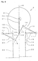
- Fig. 1 is a front view of a principal construction of a press machine according to a first embodiment of the present invention.
- Fig. 2 is a front view of a slide driving device.
- Fig. 3 is a skeleton diagram showing a line drawing of a construction of a slide driving device.
- Fig. 4 is a figure showing the slide motion of a slide driving device.
- Fig. 5 is a front view showing a slide driving device of a second embodiment of the present invention.
- Fig. 6 is a front view of a slide driving device of a third embodiment of the present invention.
- Fig. 7 is a front view of a press machine of a fourth embodiment of the present invention.
- Fig. 8 is a front view of a slide driving device of a fifth embodiment of the present invention.
-
- Referring to Figs. 1 through 4, the first embodiment of a
press machine 1 is shown, including aslide driving device 2 mounted to aframe 3. Theslide driving device 2 operates aslide 8 through a pair ofplungers 22 In Figs. 1 through 4, the motion of theslide driving device 2 andslide 8 are shown as solid and two-dashed lines. The solid line indicates whenslide driving device 2 is at a top dead center, position and the two-dashed line indicates whenslide driving device 2 is at a bottom dead center position. - A
motor 4 rests onframe 3 ofpress machine 1. Abelt 5 attaches themotor 4 to afly wheel 6. Thebelt 5, transmits power frommotor 4 to thefly wheel 6 through a disconnecting clutch (not shown). Thefly wheel 6 rotates on a driving shaft (not shown). - A bolster 7 is fixed to the
frame 3 below the slide 8 (as shown to the bottom of Figure 1). In operation, theslide 8 can be raised and lowered relative to the bolster 7. In operation, an upper mold and a lower mold (both not shown) are mounted on theslide 8 and bolster 7, respectively. Theslide 8 andplungers 22 are both guided by guide devices(not shown) relative.to the bolster 7. - A pair of fixed support point pins 11 are fixed on the respective left and right hand side positions on an upper part of the frame 3 (shown to the left and right of the drawing in Figure 1). The fixed support point pins 11 are equidistant from a
vertical plane 9. The fixed support point pins 11 are also on the same horizontal plane. Thevertical plane 9 is in the center of the left and right positions. It is to be understood, that thevertical plane 9 is at a representational center position of theslide driving device 2. It is to be further understood, thatvertical surface 9 allows a positional component comparison to be made throughout the operation ofslide driving device 2. - An
upper toggle link 12 is pivotably mounted on each of the fixed support point pins 11. The upper toggle links 12 each include three fixed links at predetermined first, second, and third positions which are substantially equidistant from the respective fixed support point pins 11. - A first
support point pin 14 is provided at the first position on eachupper toggle link 12, a secondsupport point pin 16 is provided at the second position on eachupper toggle link 12 and adynamic balancer 31 is provided at the third position on eachupper toggle link 12. - The
dynamic balancer 31 includes a weight portion (not shown) that corresponds to a weight of thefirst link 13 portion of eachupper toggle link 12. - The weight of the
dynamic balancer 31 is selected and positioned to dampen operating vibration by countering the forces, effects, and motions of theslide 8. - The distance from the fixed
support point pin 11 to the firstsupport point pin 14 is the same as the distance from the fixedsupport pin 11 to the secondsupport point pin 16. - A
first link 13 is defined between the fixedsupport point pin 11 and the firstsupport point pin 14, Asecond link 15 is defined between the fixedsupport point pin 11 and the secondsupport point pin 16. Athird link 30 is defined between thesupport point pin 11 anddynamic balancer 31. Thethird link 30 is perpendicular to thesecond link 15 and extends in a direction away from thevertical plane 9. - In operation, the first support point pins 14, second support point pins 16, and
dynamic balancers 31 move along a pair ofcircular arcs 10, of an equal radius (shown by dashed lines). The fixed support point pins 11 are the centers ofcircular arcs 10. - When the left and right hand side first support point pins 14 are both positioned at tangent points on a common
tangent line 19 of the circular arcs 10 (shown by the dashed line), the left and right hand side first links 13 are parallel to each other. A connectinglink 17 connects thefirst links 13 in this position at first support point pins 14. At this position, the connectinglink 17 is at a pitch of the distance between left and right first support point pins 14. - A center
support point pin 18 is provided at a midpoint along the connectinglink 17. In operation, thefirst links 13 swing alongcircular arcs 10 and the centersupport point pin 18 has an approximate linear motion along the inner tangent line 29 due to the Watt-link-type mechanism so defined. The present invention takes advantage of the fact that the pivot swinging angles for each of the left and right hand side first links 13 are approximately equal at that time. - A connecting
rod 21 extends from the centersupport point pin 18. The connectingrod 21 has a large end and a small end. The small end of connectingrod 21 is rotatably connected to the centersupport point pin 18. The large end of the connectingrod 21 is rotatably connected to an eccentric part (not shown) of acrank shaft 20. - The
crank shaft 20 includes a shaft core (not shown) positioned in a front-back direction of the press machine in a line perpendicular to the plane of the drawing of Figure 1. - The
plungers 22 extend from respective left and right hand side points on theslide 8, toward respective fixed support point pins 11. Eachplunger 22 has an upper end positioned directly below the fixed support point pins 11. The second support point pins 16 of thesecond links 15 rotatably connected the upper ends of theplungers 22 through a pair of lower toggle links 23. Thelower toggle links 23 have equal lengths. The second support pins 16 operate on an outside portion ofplungers 22, distant from thevertical plane 9. - As the
crank shaft 20 rotates, the eccentric part of the crank transmits motion to the large end of connectingrod 21. The driving motion of the connectingrod 21 transmits the motion to the centersupport point pin 18 through the small end of connectingrod 21 so that theupper links 12 pivot about their respective axes. Crankshaft 20 rotates through a complete circle of 360 degrees (the crank angle) relative to thevertical plane 9. Thecrank shaft 20, connects to thefly wheel 6 through the disconnecting clutch. - As crank
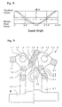
shaft 20 rotates in the direction of the arrow shown in Figure 1 and Figure 2, the eccentric part of the crank drives the connectingrod 21 in an up-down reciprocal motion. As connectingrod 21 moves, the connectinglink 17 moves the upper toggle links 12 through the respective first support point pins 14. When crankshaft 20 is rotated so that connectingrod 21 is at a crank angle of 185.5 degrees,slide 8 is at a bottom dead center position relative to the bolster 7. It should be understood that a top dead position is defined opposite the bottom dead center position, at substantially 0 or 360 crank angle degrees. During continuous cyclic operation, slide 8 is at the bottom dead center position once during each cycle. - The continuous motion of the
slide 8 is shown by the continuous line in Fig. 4. At crank angles of 90 and 270 degrees, theslide driving mechanism 2 is at a 1/3 stroke position. For comparison purposes only a standard sine wave, which is partially shifted, is shown by the dashed line in Figure 4. It should be understood that the speed ofslide 8 slows near the bottom dead center position at 185.5 degrees. It should be further understood that the above described embodiment is only a first embodiment of the present invention and many other embodiments are possible. - Additionally referring now to Fig. 5, showing a second embodiment of the
slide driving device 2. On the right hand side of the drawing in Fig. 5, theslide 8 is at the top dead center position. On the left hand side of the drawing in Fig. 5,slide 8 is at the bottom dead center position. In this embodiment, second support point pins 16 operate on the inward side ofplungers 22 relative to thevertical plane 9. It is to be understood thatdynamic balancers 31 may additionally have a shape or weight adapted to compensate for the operating forces in this second embodiment. - Additionally referring now to Fig. 6, which shows a third embodiment of the
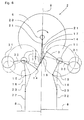
slide driving device 2. The right hand side portion of the drawing in Figure 6 shows theslide 8 at the top dead position and the left hand side portion of the drawing shows theslide 8 at the bottom dead center position. In this embodiment, crankshaft 20,fly wheel 6, and connectingrod 21 are positioned above thecenter support point 18 the and connectinglink 17. - Additionally referring now to Fig. 7, showing a fourth embodiment of
slide driving device 2 andpress machine 1. Again, the right portion of the figure showsslide 8 at the top dead center position, and the left portion of the figure showsslide 8 at the bottom dead center position. - In this embodiment, the positions of the fixed support point pins 11 are at different relative heights. The
plungers 22 have different respective lengths to position theslide 8 horizontally with respect to the bolster 7. The connectinglink 17 moves substantially vertically, along thevertical plane 9 such that the side-to-side swinging movement of the connectingrod 21 is minimized. Since the swinging movement of the connectingrod 21 is minimized one vibration source is minimized. - Additionally referring now to Fig. 8 which shows a fifth embodiment of the
slide driving device 2 according to the present invention. Again, the right hand side portion of the drawing showsslide 8 at the top dead center position, and the left hand side portion of the drawing showsslide 8 at the bottom dead center position. - In this embodiment crank
shaft 20,fly wheel 6, and connectingrod 21 are positioned above the centersupport point pin 18. The fixed support point pins 11 are positioned horizontally distant from and vertically aboveplungers 22. Thesecond links 15 are positioned relative toplungers 22 such that the second support point pins 16 are substantially directly above theplungers 22 during operation. - Since, the distance between left and right support point pins 11 is larger than that shown in the embodiment of Figures 1 to 7, the lengths of the
first links 13 are longer than the lengths ofsecond links 15. The swinging angle of thesecond links 15 is small relative to the swinging angle offirst links 13. Thus, second support point pins 16 move generally vertically relative toplungers 22 andlower toggle links 23 are made unitary withplungers 22. It is to be understood, that due to the minimal horizontal movement of second support points 16, the plungers may be rotatably fixed to the second support points 16, thereby simplifying construction. - In this fifth embodiment, the movement of
slide 8 remains an approximate sine curve, but since there is no longer alower toggle link 23 effect there is no reduction in speed near the bottom dead center position. - It is to be understood that, while in each of the above embodiments the small end of connecting
rod 21 connects with centersupport point pin 18 at a midpoint of connectinglink 17, the invention may also be implemented by connecting along either side of connectinglink 17 or eitherupper toggle link 12. - It is to be further understood that by forming a Watt-link-type mechanism, the parallelism of
slide driving device 2 may be maintained. The parallelism is maintained by connecting first support point pins 14 of eachupper toggle link 12 through a single connecting link. Since the single connecting link involves pin-type connections (or similar simplified connections), construction is simplified and high precision in construction is achievable. - It is to be further understood that the placement, weight, and shape of
dynamic balancers 31, positioned on upper toggle links 12, act to minimize and suppress the operating vibration ofpress machine 1. As a result,press machine 1 may be simply constructed with smaller parts, thus reducing construction time and cost. - It is to be further understood that crank
shaft 20 may be positioned near the center ofpress machine 1, thus reducing the total height ofpress machine 1, increasing operational stability, and allowing narrower or wider spacing betweenplungers 22 according to customer need. - It is to be further understood, that crank
shaft 20 may be positioned above upper toggle links 12, thus allowing a shorter length forplungers 22, simplifying movement, and maintaining operational parallelism. - It is to be further understood, that the distance between upper toggle links 12 may be increased so that the swing angle of second links15 is small compared to the swing angle of
first links 13. Since the second support point pins 16 move substantially vertically,plungers 22 may be made unitary with lower toggle links 23. As a result, parallelism is easily maintained and the connecting parts may be simplified thus reducing costs and allowing increased precision. - Although only a single or few exemplary embodiments of this invention have been described in detail above, those skilled in the art will readily appreciate that many modifications are possible in the exemplary embodiment(s) without materially departing from the novel teachings and advantages of this invention. Accordingly, all such modifications are intended to be included within the scope of this invention as defined in the following claims. In the claims, means-plus-function clauses are intended to cover the structures described herein as performing the recited function and not only structural equivalents but also equivalent structures. Thus although a nail and screw may not be structural equivalents in that a nail relies entirely on friction between a wooden part and a cylindrical surface whereas a screw's helical surface positively engages the wooden part, in the environment of fastening wooden parts, a nail and a screw may be equivalent structures.
- Having described preferred embodiments of the invention with reference to the accompanying drawings, it is to be understood that the invention is not limited to those precise embodiments, and that various changes and modifications may be effected therein by one skilled in the art without departing from the scope or spirit of the invention as defined in the appended claims.
Claims (19)
- Apparatus for moving a slide (8) in a machine tool (1) of the type in which the slide is movable between a bottom dead center position and a top dead center position;
characterised in that the said apparatus comprises:first and second actuator members (12) rotatably mounted about respective first and second pivot axes (11);a connecting member (21) pivotally connected to the said first and second actuator members at respective first and second pivot points (14) radially spaced from their respective pivot axis (11);the geometry being such that the connecting member extends substantially tangential to the circumferential movement paths (10) of the said first and second pivot points when the mid point (18) of the connecting member is coincident with a line between the respective first and second pivot axes; and,first and second connecting means (16,22,23) for connecting respective first and second actuator members to the slide, thereby to translate movement of the said connecting member to translation of the slide. - A slide driving device comprising:at least first and second upper toggle means;a rotation center on each said first and second upper toggle means;said rotation center permitting said first and second upper toggle means to rotate in an arc;a first point pin on each said first and second upper toggle means;a first link connects each said rotation center to each respective said first point pin;a connecting link connecting said first and second upper toggle means at said first point pins on a common inner tangent line to each said arc where said first links are parallel;a first and second plunger for driving a slide in a cycle;said first and second plungers operably connect to said first and second upper toggle means;said connecting link being effective to transfer a guiding displacement to said first and second upper toggle means; andsaid first and second upper toggle means transferring said guiding displacement to said plungers and said slide operates through said cycle.
- A slide driving device according to claim 2, further comprising:a crank shaft having at least a first eccentric part;said first eccentric part having an eccentric displacement;a connecting rod connects said first eccentric part to said connecting link; andsaid connecting rod operably transfers said eccentric displacement to said connecting link whereby said slide operates through said cycle.
- A slide driving device according to claim 3, further comprising:a second point pin on each said first and second upper toggle means;a second link connects each said rotation center to each respective said second point pin;at least first and second lower toggle links;said first and second lower toggle links operably connected to respective said first and second plungers; andsaid first and second upper toggle means operably transfers said guiding displacement through said second links to respective said first and second lower toggle links and said slide whereby said slide operates through said cycle.
- A slide driving device according to claim 4, further comprising:a first balancer on said first upper toggle means;a second balancer on said second upper toggle means;each said first and second balancer has a weight and a shape adaptable to each respective said first link;a third link connects each said rotation center to each respective said first and second balancer;each said third link being positioned relative to each said second link; andsaid first and second balancers at positions to minimize a vibration when said first and second plungers drive said slide in said cycle, whereby said vibration of said slide driving device is minimized.
- A slide driving device, according to claim 5, wherein:said first upper toggle means is a first upper toggle element;said second upper toggle means is a second upper toggle element; andsaid first and second upper toggle elements operably transfer said guiding displacement from said connecting link to each said respective second link, whereby said slide operates through said displacement cycle.
- A slide driving device, according to claim 5, whereinsaid first, second, and third links have a similar length;said arc for each respective said first and second upper toggle means has a similar radius;each said rotation center above each respective said plunger;each said rotation center equidistant from a common center line between said first and second upper toggle means;said crank shaft below said connection rod; andsaid second support pins and said first and second lower toggle links operable on first outer sides of each respective said plunger, whereby said slide operates through said displacement cycle.
- A slide driving device according to claim 5, wherein:said first, second, and third links have the same length;said arc for each respective said first and second upper toggle means has the same radius;each said rotation center above each respective said plunger;each said rotation center equidistant from a common center line between said first and second upper toggle means;said crank shaft below said connection rod; andsaid second support pins and said first and second lower toggle links operable on an inner side of each respective said plunger, whereby said slide operates through said displacement cycle.
- A slide driving device according to claim 5, wherein:said first, second, and third links have the same length;said arc for each respective said first and second upper toggle means has the same radius;each said rotation center above each said plunger;each said rotation center equidistant from a common center line between said first and second upper toggle means;said crank shaft above said connection rod; andsaid second support pins and said first and second lower toggle links operable on an inner side of each respective said plunger, whereby said slide operates through said displacement cycle.
- A slide driving device according to claim 5, wherein:each said rotation center is a first distance from a common center line between said first and second upper toggle means;each said plunger is a second distance from said common center line;said first distance greater than said second distance;each said first link longer than each said second link;each said second point pin operable substantially above each respective said plunger and respective said toggle link;said crank shaft above said connection rod along said common center line; andeach said lower toggle link and each respective said plunger being substantially unitary and operable parallel to said common center line, whereby said slide operates through said displacement cycle with reduced vibration.
- A slide driving device according to claim 7, wherein:said rotation center is a first rotation center for said first upper toggle means;said rotation center is a second rotation center for said second upper toggle means;said first rotation center and said second rotation center at different distances above each respective said plunger;said first point pins substantially tangent said common center line; andsaid connecting rod and said connecting link operate substantially along said common center line and minimize vibration in said slide driving device when said first and second plungers drive said slide in said displacement cycle.
- A slide driving device comprising:a first and second upper toggle means;said first and second upper toggle means being equidistant from a common center line;said first and second upper toggle means being operable in first and second arcs;a connecting link operably joining said first and second upper toggle means at an inner tangent line to said first and second arcs;a first and second lower toggle means;said first and second lower toggle means operably joined to respective said first and second upper toggle means;a slide element operable by said first and second lower toggle means in a displacement cycle;said connecting link receives a driving displacement; andsaid first and second upper toggle means transmit said driving displacement to said first and second lower toggle means and said slide element and said slide operates in said displacement cycle to minimize vibration.
- A slide driving device for a press machine, comprising:a left and a right upper toggle link equidistant from a common center;said left and right upper toggle links pivotably mounted on respective fixed support point pins;a first support link on each said left and right upper toggle links;each said first support link being operable in an arc;each said first support links having equal lengths;a connecting link operably connecting each said first support links along a common inner tangent line to each said arc when said first support links are parallel to each other;a connecting rod connects said connecting link to an eccentric portion on a crank shaft;a first and second lower toggle links connect second support point pins on said left and right upper toggle links along a second link;said second links on each said left and right upper toggle link;said second links rotatably connect to said left and right lower toggle links and to at least left and right points on a slide; andsaid connecting rod transmits a guiding displacement to said left and right upper toggle links and said lower toggle links, to said slide to drive said slide through a displacement cycle.
- A slide driving device for a press machine, according to claim 12, further comprising:a dynamic balancer are mounted to an outer end of each said left and right upper toggle links along a third link; andeach said dynamic balancer has a weight and a shape selected to minimize a vibration of said slide driving device.
- A slide driving device for a press machine, according to claim 13, further comprising:a left and right plunger upright at left and right points of said slide;a first end of each said left and right plungers operably connect to respective said left and right lower toggle links;said left and right fixed support points horizontally equidistant from said center line above respective said left and right plungers;said second support point pins on an outer side of each said left and right plunger; andsaid crank shaft is below said connecting link.
- A slide driving device for a press machine, according to claim 13, further comprising:a left and right plunger upright at left and right points of said slide;a first end of each said left and right plungers operably connect to each respective said left and right lower toggle links;said left and right fixed support points equidistant from said common center line above each respective said left and right plunger;said second support point pins on inner sides of each respective said left and right plunger; andsaid crank shaft below said connecting link.
- A slide driving device for a press machine, according to claim 13, further comprising:a left and right plunger upright at left and right points of said slide;first ends of each said left and right plunger operably connect to each respective said left and right lower toggle link;said left and right fixed support points equidistant from said center line and outward from directly above said plungers;said second support point pins on inner sides of each respective said left and right plunger; andsaid crank shaft is above said connecting link.
- A slide driving device for a press machine, according to claim 13, further comprising:a left and right plunger upright at left and right points of said slide;first ends of said left and right plungers operably connect to each respective said left and right lower toggle link;said left and right fixed support points at first and second positions;said first and second positions above each said left and right plunger at different distances;said second support point pins on outer sides of each respective said left and right plunger; andsaid crank shaft is placed below said connecting link.
- A slide driving device for a press machine, according to claim 13, further comprising:said left and right fixed support points are horizontally equidistant from said center line outward from each respective said left and right points of said slide;said second links perpendicular to said center line when each respective said second support point pin is directly above each respective said left and right points on said slide; andsaid crank shaft is above said connecting link.
Applications Claiming Priority (2)
| Application Number | Priority Date | Filing Date | Title |
|---|---|---|---|
| JP2000044574 | 2000-02-22 | ||
| JP2000044574A JP2001232497A (en) | 2000-02-22 | 2000-02-22 | Slide driving device for press machine |
Publications (3)
| Publication Number | Publication Date |
|---|---|
| EP1127684A2 true EP1127684A2 (en) | 2001-08-29 |
| EP1127684A3 EP1127684A3 (en) | 2002-04-17 |
| EP1127684B1 EP1127684B1 (en) | 2008-09-24 |
Family
ID=18567310
Family Applications (1)
| Application Number | Title | Priority Date | Filing Date |
|---|---|---|---|
| EP01301619A Expired - Lifetime EP1127684B1 (en) | 2000-02-22 | 2001-02-22 | Slide driving apparatus of press machine |
Country Status (6)
| Country | Link |
|---|---|
| US (1) | US6629494B2 (en) |
| EP (1) | EP1127684B1 (en) |
| JP (1) | JP2001232497A (en) |
| KR (1) | KR100787603B1 (en) |
| DE (1) | DE60135887D1 (en) |
| TW (1) | TW539610B (en) |
Cited By (2)
| Publication number | Priority date | Publication date | Assignee | Title |
|---|---|---|---|---|
| EP1650015A1 (en) * | 2004-10-25 | 2006-04-26 | Haulick + Roos GmbH | Press, punch press or forming apparatus |
| CN102284660A (en) * | 2010-06-21 | 2011-12-21 | 南京农业大学 | Dynamic balancing mechanism of high-speed symmetric equal-length knuckle-lever press |
Families Citing this family (3)
| Publication number | Priority date | Publication date | Assignee | Title |
|---|---|---|---|---|
| JP4885116B2 (en) * | 2007-11-27 | 2012-02-29 | 三菱重工業株式会社 | Vibration suppression mechanism of gear processing machine |
| CN103568349B (en) * | 2012-08-10 | 2015-10-14 | 上海工程技术大学 | Tablet press machine Guide rod upper punch mechanism |
| RU2745914C1 (en) * | 2020-06-25 | 2021-04-02 | Федеральное государственное бюджетное образовательное учреждение высшего образования "Сибирский государственный индустриальный университет", ФГБОУ ВО "СибГИУ" | Leverage mechanism of a press |
Citations (5)
| Publication number | Priority date | Publication date | Assignee | Title |
|---|---|---|---|---|
| US4630516A (en) * | 1982-09-06 | 1986-12-23 | Mabu-Pressen Maschinenfabrik Karl Burkard Kg | Eccentric press |
| JPH08118082A (en) * | 1994-10-24 | 1996-05-14 | Kiyouri Kogyo Kk | Press machine |
| JPH1099995A (en) * | 1996-09-26 | 1998-04-21 | Aida Eng Ltd | Slide device of press using link |
| JPH11197888A (en) * | 1998-01-09 | 1999-07-27 | Nippon Densan Kyoori Kk | Press |
| JPH11320187A (en) * | 1998-05-07 | 1999-11-24 | Aida Eng Ltd | Slide driving device of link press |
Family Cites Families (6)
| Publication number | Priority date | Publication date | Assignee | Title |
|---|---|---|---|---|
| US3808912A (en) * | 1972-11-21 | 1974-05-07 | Minster Machine Co | Arrangement for dynamic balancing of a mechanical press, especially a high speed mechanical press |
| JPS6257800A (en) * | 1985-09-07 | 1987-03-13 | Aida Eng Ltd | Dynamical balancing device for press |
| JPH0755399B2 (en) * | 1992-10-05 | 1995-06-14 | 株式会社山田ドビー | Power transmission device for press machine |
| JPH10128597A (en) * | 1996-10-28 | 1998-05-19 | Aida Eng Ltd | Slide drive device for press using link |
| JPH10128596A (en) * | 1996-10-28 | 1998-05-19 | Aida Eng Ltd | Slide drive device for press using link |
| JPH1199995A (en) * | 1997-09-29 | 1999-04-13 | Toshio Matsubara | Runway shortening ground run |
-
2000
- 2000-02-22 JP JP2000044574A patent/JP2001232497A/en active Pending
-
2001
- 2001-02-16 US US09/785,029 patent/US6629494B2/en not_active Expired - Fee Related
- 2001-02-21 TW TW090103969A patent/TW539610B/en not_active IP Right Cessation
- 2001-02-22 DE DE60135887T patent/DE60135887D1/en not_active Expired - Lifetime
- 2001-02-22 KR KR1020010009004A patent/KR100787603B1/en not_active IP Right Cessation
- 2001-02-22 EP EP01301619A patent/EP1127684B1/en not_active Expired - Lifetime
Patent Citations (5)
| Publication number | Priority date | Publication date | Assignee | Title |
|---|---|---|---|---|
| US4630516A (en) * | 1982-09-06 | 1986-12-23 | Mabu-Pressen Maschinenfabrik Karl Burkard Kg | Eccentric press |
| JPH08118082A (en) * | 1994-10-24 | 1996-05-14 | Kiyouri Kogyo Kk | Press machine |
| JPH1099995A (en) * | 1996-09-26 | 1998-04-21 | Aida Eng Ltd | Slide device of press using link |
| JPH11197888A (en) * | 1998-01-09 | 1999-07-27 | Nippon Densan Kyoori Kk | Press |
| JPH11320187A (en) * | 1998-05-07 | 1999-11-24 | Aida Eng Ltd | Slide driving device of link press |
Non-Patent Citations (4)
| Title |
|---|
| PATENT ABSTRACTS OF JAPAN vol. 1996, no. 09, 30 September 1996 (1996-09-30) & JP 08 118082 A (KIYOURI KOGYO KK), 14 May 1996 (1996-05-14) * |
| PATENT ABSTRACTS OF JAPAN vol. 1998, no. 09, 31 July 1998 (1998-07-31) & JP 10 099995 A (AIDA ENG LTD), 21 April 1998 (1998-04-21) * |
| PATENT ABSTRACTS OF JAPAN vol. 1999, no. 12, 29 October 1999 (1999-10-29) & JP 11 197888 A (NIPPON DENSAN KYOORI KK), 27 July 1999 (1999-07-27) * |
| PATENT ABSTRACTS OF JAPAN vol. 2000, no. 02, 29 February 2000 (2000-02-29) & JP 11 320187 A (AIDA ENG LTD), 24 November 1999 (1999-11-24) * |
Cited By (2)
| Publication number | Priority date | Publication date | Assignee | Title |
|---|---|---|---|---|
| EP1650015A1 (en) * | 2004-10-25 | 2006-04-26 | Haulick + Roos GmbH | Press, punch press or forming apparatus |
| CN102284660A (en) * | 2010-06-21 | 2011-12-21 | 南京农业大学 | Dynamic balancing mechanism of high-speed symmetric equal-length knuckle-lever press |
Also Published As
| Publication number | Publication date |
|---|---|
| EP1127684B1 (en) | 2008-09-24 |
| US20010020421A1 (en) | 2001-09-13 |
| TW539610B (en) | 2003-07-01 |
| KR20010083244A (en) | 2001-08-31 |
| JP2001232497A (en) | 2001-08-28 |
| KR100787603B1 (en) | 2007-12-21 |
| DE60135887D1 (en) | 2008-11-06 |
| US6629494B2 (en) | 2003-10-07 |
| EP1127684A3 (en) | 2002-04-17 |
Similar Documents
| Publication | Publication Date | Title |
|---|---|---|
| KR100198474B1 (en) | Mechanical pressing machine | |
| US5467706A (en) | Mechanical pressing machine with dynamic balancing device | |
| EP1162057B1 (en) | A slide drive device for a press | |
| EP1127684A2 (en) | Slide driving apparatus of press machine | |
| EP1175993A2 (en) | Driving device for a press machine | |
| US5467633A (en) | Mechanical pressing machine | |
| US5605096A (en) | Mechanical pressing machine with dynamic balancing device | |
| JP2649318B2 (en) | Press machine | |
| KR0157241B1 (en) | Mechanical pressing machine | |
| EP1207038A2 (en) | Press machine | |
| JP3159449B2 (en) | Lever device having fixed fulcrum, oscillating power point and oscillating operation point, and mechanical device using the same | |
| JPH09155595A (en) | Press machine | |
| JP3910289B2 (en) | Press machine | |
| JPS6160300A (en) | Machine press | |
| US5737966A (en) | Pressing machine with reciprocating slide | |
| JPH08118082A (en) | Press machine | |
| RU1810211C (en) | Mechanical press | |
| JP4153749B2 (en) | Press machine | |
| JP2003080398A (en) | Press | |
| JP3850499B2 (en) | Crank device | |
| KR20160004113U (en) | Counterweight balancing apparatus of forming machine | |
| KR0160533B1 (en) | Mechanical pressing machine | |
| JP2003320490A (en) | Link press | |
| JPH10286700A (en) | Device for regulating die height of press machine | |
| JPH0528598U (en) | Gravity balancer for press machine |
Legal Events
| Date | Code | Title | Description |
|---|---|---|---|
| PUAI | Public reference made under article 153(3) epc to a published international application that has entered the european phase |
Free format text: ORIGINAL CODE: 0009012 |
|
| AK | Designated contracting states |
Kind code of ref document: A2 Designated state(s): AT BE CH CY DE DK ES FI FR GB GR IE IT LI LU MC NL PT SE TR Kind code of ref document: A2 Designated state(s): CH DE IT LI |
|
| AX | Request for extension of the european patent |
Free format text: AL;LT;LV;MK;RO;SI |
|
| PUAL | Search report despatched |
Free format text: ORIGINAL CODE: 0009013 |
|
| AK | Designated contracting states |
Kind code of ref document: A3 Designated state(s): AT BE CH CY DE DK ES FI FR GB GR IE IT LI LU MC NL PT SE TR |
|
| AX | Request for extension of the european patent |
Free format text: AL;LT;LV;MK;RO;SI |
|
| RIC1 | Information provided on ipc code assigned before grant |
Free format text: 7B 30B 1/14 A, 7B 30B 15/00 B, 7B 30B 1/06 B |
|
| 17P | Request for examination filed |
Effective date: 20021003 |
|
| AKX | Designation fees paid |
Free format text: CH DE IT LI |
|
| 17Q | First examination report despatched |
Effective date: 20040211 |
|
| GRAP | Despatch of communication of intention to grant a patent |
Free format text: ORIGINAL CODE: EPIDOSNIGR1 |
|
| GRAS | Grant fee paid |
Free format text: ORIGINAL CODE: EPIDOSNIGR3 |
|
| GRAA | (expected) grant |
Free format text: ORIGINAL CODE: 0009210 |
|
| RAP1 | Party data changed (applicant data changed or rights of an application transferred) |
Owner name: AIDA ENGINEERING CO., LTD. |
|
| AK | Designated contracting states |
Kind code of ref document: B1 Designated state(s): CH DE IT LI |
|
| REG | Reference to a national code |
Ref country code: CH Ref legal event code: EP Ref country code: CH Ref legal event code: NV Representative=s name: BUGNION S.A. |
|
| REF | Corresponds to: |
Ref document number: 60135887 Country of ref document: DE Date of ref document: 20081106 Kind code of ref document: P |
|
| PLBE | No opposition filed within time limit |
Free format text: ORIGINAL CODE: 0009261 |
|
| STAA | Information on the status of an ep patent application or granted ep patent |
Free format text: STATUS: NO OPPOSITION FILED WITHIN TIME LIMIT |
|
| 26N | No opposition filed |
Effective date: 20090625 |
|
| PGFP | Annual fee paid to national office [announced via postgrant information from national office to epo] |
Ref country code: CH Payment date: 20110223 Year of fee payment: 11 Ref country code: DE Payment date: 20110225 Year of fee payment: 11 Ref country code: IT Payment date: 20110224 Year of fee payment: 11 |
|
| REG | Reference to a national code |
Ref country code: CH Ref legal event code: PL |
|
| PG25 | Lapsed in a contracting state [announced via postgrant information from national office to epo] |
Ref country code: LI Free format text: LAPSE BECAUSE OF NON-PAYMENT OF DUE FEES Effective date: 20120229 Ref country code: CH Free format text: LAPSE BECAUSE OF NON-PAYMENT OF DUE FEES Effective date: 20120229 |
|
| PG25 | Lapsed in a contracting state [announced via postgrant information from national office to epo] |
Ref country code: IT Free format text: LAPSE BECAUSE OF NON-PAYMENT OF DUE FEES Effective date: 20120222 |
|
| REG | Reference to a national code |
Ref country code: DE Ref legal event code: R119 Ref document number: 60135887 Country of ref document: DE Effective date: 20120901 |
|
| PG25 | Lapsed in a contracting state [announced via postgrant information from national office to epo] |
Ref country code: DE Free format text: LAPSE BECAUSE OF NON-PAYMENT OF DUE FEES Effective date: 20120901 |