EP1127675A2 - Injection molding machine capable of reducing power consumption - Google Patents
Injection molding machine capable of reducing power consumption Download PDFInfo
- Publication number
- EP1127675A2 EP1127675A2 EP01101839A EP01101839A EP1127675A2 EP 1127675 A2 EP1127675 A2 EP 1127675A2 EP 01101839 A EP01101839 A EP 01101839A EP 01101839 A EP01101839 A EP 01101839A EP 1127675 A2 EP1127675 A2 EP 1127675A2
- Authority
- EP
- European Patent Office
- Prior art keywords
- charger
- electric power
- voltage
- value
- motor
- Prior art date
- Legal status (The legal status is an assumption and is not a legal conclusion. Google has not performed a legal analysis and makes no representation as to the accuracy of the status listed.)
- Granted
Links
- 238000001746 injection moulding Methods 0.000 title claims description 49
- 238000007599 discharging Methods 0.000 claims abstract description 41
- 230000005611 electricity Effects 0.000 claims abstract description 20
- 238000000034 method Methods 0.000 claims description 17
- 230000006698 induction Effects 0.000 abstract description 35
- 238000000465 moulding Methods 0.000 description 10
- 230000001133 acceleration Effects 0.000 description 5
- 238000002347 injection Methods 0.000 description 5
- 239000007924 injection Substances 0.000 description 5
- 238000010586 diagram Methods 0.000 description 3
- 239000011347 resin Substances 0.000 description 3
- 229920005989 resin Polymers 0.000 description 3
- 230000000694 effects Effects 0.000 description 2
- 230000001172 regenerating effect Effects 0.000 description 2
- 238000009499 grossing Methods 0.000 description 1
- 238000005259 measurement Methods 0.000 description 1
- 230000002093 peripheral effect Effects 0.000 description 1
- 230000008929 regeneration Effects 0.000 description 1
- 238000011069 regeneration method Methods 0.000 description 1
Images

Classifications
-
- B—PERFORMING OPERATIONS; TRANSPORTING
- B29—WORKING OF PLASTICS; WORKING OF SUBSTANCES IN A PLASTIC STATE IN GENERAL
- B29C—SHAPING OR JOINING OF PLASTICS; SHAPING OF MATERIAL IN A PLASTIC STATE, NOT OTHERWISE PROVIDED FOR; AFTER-TREATMENT OF THE SHAPED PRODUCTS, e.g. REPAIRING
- B29C45/00—Injection moulding, i.e. forcing the required volume of moulding material through a nozzle into a closed mould; Apparatus therefor
- B29C45/17—Component parts, details or accessories; Auxiliary operations
- B29C45/76—Measuring, controlling or regulating
- B29C45/7666—Measuring, controlling or regulating of power or energy, e.g. integral function of force
-
- H—ELECTRICITY
- H02—GENERATION; CONVERSION OR DISTRIBUTION OF ELECTRIC POWER
- H02M—APPARATUS FOR CONVERSION BETWEEN AC AND AC, BETWEEN AC AND DC, OR BETWEEN DC AND DC, AND FOR USE WITH MAINS OR SIMILAR POWER SUPPLY SYSTEMS; CONVERSION OF DC OR AC INPUT POWER INTO SURGE OUTPUT POWER; CONTROL OR REGULATION THEREOF
- H02M1/00—Details of apparatus for conversion
- H02M1/16—Means for providing current step on switching, e.g. with saturable reactor
-
- B—PERFORMING OPERATIONS; TRANSPORTING
- B29—WORKING OF PLASTICS; WORKING OF SUBSTANCES IN A PLASTIC STATE IN GENERAL
- B29C—SHAPING OR JOINING OF PLASTICS; SHAPING OF MATERIAL IN A PLASTIC STATE, NOT OTHERWISE PROVIDED FOR; AFTER-TREATMENT OF THE SHAPED PRODUCTS, e.g. REPAIRING
- B29C45/00—Injection moulding, i.e. forcing the required volume of moulding material through a nozzle into a closed mould; Apparatus therefor
- B29C45/17—Component parts, details or accessories; Auxiliary operations
-
- B—PERFORMING OPERATIONS; TRANSPORTING
- B29—WORKING OF PLASTICS; WORKING OF SUBSTANCES IN A PLASTIC STATE IN GENERAL
- B29C—SHAPING OR JOINING OF PLASTICS; SHAPING OF MATERIAL IN A PLASTIC STATE, NOT OTHERWISE PROVIDED FOR; AFTER-TREATMENT OF THE SHAPED PRODUCTS, e.g. REPAIRING
- B29C45/00—Injection moulding, i.e. forcing the required volume of moulding material through a nozzle into a closed mould; Apparatus therefor
- B29C45/17—Component parts, details or accessories; Auxiliary operations
- B29C45/76—Measuring, controlling or regulating
-
- B—PERFORMING OPERATIONS; TRANSPORTING
- B29—WORKING OF PLASTICS; WORKING OF SUBSTANCES IN A PLASTIC STATE IN GENERAL
- B29C—SHAPING OR JOINING OF PLASTICS; SHAPING OF MATERIAL IN A PLASTIC STATE, NOT OTHERWISE PROVIDED FOR; AFTER-TREATMENT OF THE SHAPED PRODUCTS, e.g. REPAIRING
- B29C45/00—Injection moulding, i.e. forcing the required volume of moulding material through a nozzle into a closed mould; Apparatus therefor
- B29C45/17—Component parts, details or accessories; Auxiliary operations
- B29C2045/1784—Component parts, details or accessories not otherwise provided for; Auxiliary operations not otherwise provided for
- B29C2045/1792—Machine parts driven by an electric motor, e.g. electric servomotor
-
- B—PERFORMING OPERATIONS; TRANSPORTING
- B29—WORKING OF PLASTICS; WORKING OF SUBSTANCES IN A PLASTIC STATE IN GENERAL
- B29C—SHAPING OR JOINING OF PLASTICS; SHAPING OF MATERIAL IN A PLASTIC STATE, NOT OTHERWISE PROVIDED FOR; AFTER-TREATMENT OF THE SHAPED PRODUCTS, e.g. REPAIRING
- B29C45/00—Injection moulding, i.e. forcing the required volume of moulding material through a nozzle into a closed mould; Apparatus therefor
- B29C45/17—Component parts, details or accessories; Auxiliary operations
- B29C45/76—Measuring, controlling or regulating
- B29C45/7666—Measuring, controlling or regulating of power or energy, e.g. integral function of force
- B29C2045/7673—Recovering energy or power from drive motors
-
- B—PERFORMING OPERATIONS; TRANSPORTING
- B29—WORKING OF PLASTICS; WORKING OF SUBSTANCES IN A PLASTIC STATE IN GENERAL
- B29C—SHAPING OR JOINING OF PLASTICS; SHAPING OF MATERIAL IN A PLASTIC STATE, NOT OTHERWISE PROVIDED FOR; AFTER-TREATMENT OF THE SHAPED PRODUCTS, e.g. REPAIRING
- B29C2945/00—Indexing scheme relating to injection moulding, i.e. forcing the required volume of moulding material through a nozzle into a closed mould
- B29C2945/76—Measuring, controlling or regulating
- B29C2945/76003—Measured parameter
- B29C2945/76033—Electric current or voltage
-
- B—PERFORMING OPERATIONS; TRANSPORTING
- B29—WORKING OF PLASTICS; WORKING OF SUBSTANCES IN A PLASTIC STATE IN GENERAL
- B29C—SHAPING OR JOINING OF PLASTICS; SHAPING OF MATERIAL IN A PLASTIC STATE, NOT OTHERWISE PROVIDED FOR; AFTER-TREATMENT OF THE SHAPED PRODUCTS, e.g. REPAIRING
- B29C2945/00—Indexing scheme relating to injection moulding, i.e. forcing the required volume of moulding material through a nozzle into a closed mould
- B29C2945/76—Measuring, controlling or regulating
- B29C2945/76494—Controlled parameter
- B29C2945/76525—Electric current or voltage
-
- B—PERFORMING OPERATIONS; TRANSPORTING
- B29—WORKING OF PLASTICS; WORKING OF SUBSTANCES IN A PLASTIC STATE IN GENERAL
- B29C—SHAPING OR JOINING OF PLASTICS; SHAPING OF MATERIAL IN A PLASTIC STATE, NOT OTHERWISE PROVIDED FOR; AFTER-TREATMENT OF THE SHAPED PRODUCTS, e.g. REPAIRING
- B29C2945/00—Indexing scheme relating to injection moulding, i.e. forcing the required volume of moulding material through a nozzle into a closed mould
- B29C2945/76—Measuring, controlling or regulating
- B29C2945/76929—Controlling method
- B29C2945/76939—Using stored or historical data sets
- B29C2945/76943—Using stored or historical data sets compare with thresholds
-
- Y—GENERAL TAGGING OF NEW TECHNOLOGICAL DEVELOPMENTS; GENERAL TAGGING OF CROSS-SECTIONAL TECHNOLOGIES SPANNING OVER SEVERAL SECTIONS OF THE IPC; TECHNICAL SUBJECTS COVERED BY FORMER USPC CROSS-REFERENCE ART COLLECTIONS [XRACs] AND DIGESTS
- Y02—TECHNOLOGIES OR APPLICATIONS FOR MITIGATION OR ADAPTATION AGAINST CLIMATE CHANGE
- Y02P—CLIMATE CHANGE MITIGATION TECHNOLOGIES IN THE PRODUCTION OR PROCESSING OF GOODS
- Y02P70/00—Climate change mitigation technologies in the production process for final industrial or consumer products
- Y02P70/10—Greenhouse gas [GHG] capture, material saving, heat recovery or other energy efficient measures, e.g. motor control, characterised by manufacturing processes, e.g. for rolling metal or metal working
Definitions
- the present invention relates to an injection molding machine having an injection device and a mold opening and closing device, particularly to a motor-driven injection molding machine using motors as drive sources in the injection device and the mold opening and closing device.
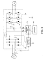
- a motor drive 10 is for a three phase induction motor IM and includes an inverter section 20 and a rectifying circuit section 30.
- the inverter section 20 includes a plurality of switching elements 21 for carrying out switching operation for respective phases of three phases.
- the rectifying circuit section 30 is realized by a condenser input type diode rectifying circuit.
- the diode rectifying circuit includes a plurality of diodes 31 for carrying out rectifying operation for respective phases of a three phase power source PS.
- the induction motor IM for the injection device or the mold opening and closing device generates regenerated electric power in deceleration thereof.
- regenerated electric power of the induction motor IM is dissipated as heat by a resistor 41 provided to a dynamic brake circuit section 40. That is, when the induction motor IM generates regenerated electric power, the switching element 42 is switched on and the regenerated electric power is dissipated by the resistor 41. From a view point of reduction of electric energy, wasteful electric energy is dissipated.
- a heat radiating device for radiating generated heat of the resistor 41 there is constituted a heat radiating device for radiating generated heat of the resistor 41 and therefore, there poses a problem of an increase in dimensions.
- An injection molding machine comprises a drive source comprising at least one motor and a motor drive, a charger for storing regenerated electric power of the motor and electric power from a power source, a charging and discharging circuit connected to the charger for charging electric power to the charger and for discharging electric power therefrom, and a controller for controlling the charger to charge electric power and for controlling the charger to supply electric power to the motor.
- the controller controls the charger by controlling the charging and discharging circuit based upon an operating condition of the injection molding machine.
- a method of providing drive power to an injection molding machine comprises the steps of controlling a charger to charge electric power from a power source and to supply electric power to a motor of the injection molding machine.
- a controller provides control signals to a charging and discharging circuit based upon an operating condition of the injection molding machine.
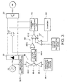
- a motor drive 50 according to the embodiment is provided with a charger 60, a charging and discharging circuit 70 and a control section 80 other than the inverter section 20 and the rectifying circuit section 30 similar to the conventional apparatus.
- the charger 60 stores regenerated electric power of the induction motor IM via the inverter section 20. When there is allowance in electric power on the side of the three phase power source PS in comparison with consumed electric power of the induction motor IM, the charger 60 stores the allowance electric power.
- the charging and discharging circuit 70 is for charging the electric power to the charger 60 and discharging the electric power from the charger 60.
- the control section 80 carries out control for making the charger 60 charge the electric power when the induction motor IM generates the regenerated electric power.
- the control section 80 carries out the control for making the charger 60 supply the electric power to the induction motor IM at accelerating the induction motor IM or the electricity interruption.
- the control section 80 also carries out the control for making the charger 60 charge the electric power when there is allowance in the electric power on the side of the three phase power source PS in comparison with the consumed electric power of the induction motor IM.
- the control section 80 includes a first voltage detecting portion 81 for detecting voltage on the input side of the inverter portion 20.
- the first voltage detecting portion 80 is realized by, for example, a smoothing condenser.
- the control section 80 also includes a first comparing portion 86. When a detected value detected by the first voltage detecting portion 81 is not lower than a predetermined value, the first comparing portion 86 outputs a charging control signal for making the charger 60 charge the electric power.
- the first comparing portion 86 outputs a discharging control signal for making the charger 60 discharge the electric power when the detected value of the first voltage detecting portion 81 becomes lower than the predetermined value.
- the first comparing portion 86 includes a second voltage detecting portion 86-1 for detecting voltage on the side of the three phase power source PS as the above-described predetermined value, a compensator 86-2, an adder 86-3, a DC link voltage instructor 86-4 and a comparator 86-5.
- the compensator 86-2 is for amplifying the detected value from the second voltage detecting portion 86-1 by a predetermined gain.
- the adder 86-3 carries out addition, mentioned later.
- the DC link voltage instructor 86-4 holds and outputs a reference value to constitute the above-described predetermined value based on an output from the adder 86-3.
- the comparator 86-5 compares the voltage detected by the second voltage detecting portion 86-1 with the detected value of the first voltage detecting portion 81 and outputs the charging control signal for making the charger 60 charge the electric power when the detected value from the first voltage detecting portion 81 is not lower than the above-described predetermined value, that is, the reference value. Further, the comparator 86-5 outputs the discharging control signal for making the charger 60 discharge the electric power when the detected value of the first voltage detecting portion 81 is lower than the reference value.
- the second voltage detecting portion 86-1 is provided because of the following reason.
- There are a plurality of kinds of the voltage value of the three phase power source such as 100 V, 110 V, 200 V and 220 V.
- the voltage value of the three phase power source PS used in the injection molding machine to which the invention is applied is selected from the above-described plurality of kinds. Therefore, the reference value at the comparator 86-5 must be set in accordance with the voltage value of the three phase power source PS.
- the first comparing portion 86 as in the above-described embodiment, the above-described setting operation is dispensed with.
- the second voltage detecting portion 86-1, the comparator 86-2, the adder 86-3, and the DC link voltage instructor 86-4 may collectively be called a setting portion.
- the first comparing portion 86 When operation of setting the reference value at the comparator 86-5 in accordance with the voltage value of the three phase power source PS, the first comparing portion 86 is constructed by the following constitution. That is, the first comparing portion 86 may be provided with a setting portion for setting the above-described predetermined value as the reference value and a comparator for comparing the set predetermined value with the detected value of the voltage detecting portion 81.
- the comparator in this case may be the same as the comparator 86-5 shown in Fig. 3. In this case, an output from the setting portion may be connected to a terminal other than an input terminal for the detected value of the first voltage detecting portion 81.
- the control section 80 is further provided with a second comparing portion 87 on an output side of the comparator 86-5.
- the second comparing portion 87 is for comparing the voltage of the charger 60 with a set value which has previously been set and outputting a control signal for making the charger 60 charge the electric power when the voltage of the charger 60 becomes lower than the set value which has previously been set. Therefore, the second comparing portion 87 is provided with a comparator 87-1 in which the voltage from the charger 60 constitutes one input and the set value which has previously been set constitutes other input as a charge amount instruction value. The comparator 87-1 outputs a charge instruction signal as a control signal when the voltage of the charger 60 becomes lower than the set value which has previously been set.
- the second comparing portion 87 is further provided with a comparator 87-2.
- the comparator 87-2 compares the charge instruction signal from the comparator 87-1 with the charging control signal and the discharging control signal from the comparator 86-5 and makes the charging and discharging circuit 70 execute operation of charging and operation of discharging electricity to and from the charger 60.
- the comparator 87-2 receives the discharging control signal from the comparator 86-5, even in the case in which the charging instruction signal is outputted from the comparator 87-1, the comparator 87-2 gives priority to the discharging control signal and makes the charging and discharging circuit 70 execute the discharging operation of the charger 60.
- the charger 60 is for storing regenerated electric power generated by the induction motor IM in deceleration via the inverter section 20 and may be a battery capable of executing floating charge.
- the control section 80 can charge the electric power to the charger 60 via the charging and discharging circuit 70 when the regenerated electric power is generated by decelerating the induction motor IM. Further, the control section 80 can carry out the control of supplying the electric power of the charger 60 to the induction motor IM in acceleration or electricity interruption. Further, the control section 80 carries out the control of making the charger 60 charge the electric power when there is allowance in the electric power on the side of the three phase power source PS in comparison with the consumed electric power of the induction motor IM. The electric power for charging the electric power in this case is supplied from the three phase power source PS.
- Such motor drive 50 is individually provided for each of the motors provided to the injection molding machine.
- motors for an injection shaft, a mold opening and closing shaft, a resin measuring shaft and an ejector shaft as main ones of the motors provided to the injection molding machine, which are induction motors.
- the electric power is supplied to the induction motor IM via the rectifying circuit section 30 and the inverter section 20.
- the induction motor IM In decelerating the induction motor IM, the induction motor IM generates the regenerated electric power. As a result, the voltage at the first voltage detecting portion 81 is increased.
- the charging control signal is outputted from the comparator 86-5 and accordingly, the regenerated electric power of the induction motor IM is charged to the charger 60 via the inverter section 20.
- the induction motor IM when the induction motor IM is accelerated, the voltage at the first voltage detecting portion 81 is reduced. In this case, the discharging control signal is outputted from the comparator 86-5. As a result, the electric power from the charger 60 is supplied to the induction motor IM via the inverter section 20. This is similar also to the case in which the voltage at the first voltage detecting portion 81 is reduced by the electricity interruption.
- a control system of a main body of the injection molding machine is provided with a backup function for storing molding conditions even when the electricity interruption occurs. Meanwhile, the electric power can be supplied from the charger 60 to the induction motor IM although not in a long period time. Hence, the control system of the main body of the injection molding machine is made to execute control operation until a molding cycle is finished even in the midst of the molding cycle when the electricity interruption occurs. In this way, there can be eliminated a state in which resin is charged into the mold in an unfinished manner. Thereby, there is facilitated restoring operation including resetting operation in restarting after electricity service is restored from the electricity interruption.
- control system of the main body of the injection molding machine is not provided with the backup function, described above, there can be constructed also a constitution in which the electric power of the charger 60 can be utilized for backup.
- the motor drive 50 of the induction motor IM, particularly, the inverter section 20 is controlled by other controller (not illustrated) for controlling thereof.
- the other controller is given instruction of decelerating and instruction of accelerating the induction motor IM in accordance with the molding conditions.
- a deceleration timing or an acceleration timing in one cycle of molding can be known beforehand for the respective induction motor. Therefore, the control section 80 can also control the charging operation and the discharging operation in accordance with the deceleration timing and the acceleration timing.
- Fig. 3 shows a charge and discharge timing setting portion 88 as the constitution therefor.
- the charge and discharge timing setting portion 88 is provided with an operating condition setting portion 88-1 and a compensator 88-2.
- the operating condition setting portion 88-1 is for setting the deceleration timing and the acceleration timing in one cycle, outputs a negative signal for executing the charging operation in deceleration and outputs a positive signal for executing the discharging operation in acceleration.
- the compensator 88-2 is for amplifying a signal from the operating condition setting portion 88-1 by a predetermined gain.
- the adder 86-3 adds the output from the compensator 86-1 and the output from the compensator 88-2.
- the present invention is not limited to the injection molding machine using the three phase power source but is applicable to an injection molding machine using a single phase power source or a two phase power source.
- the invention relates to an injection molding machine, comprising: a drive source comprising at least one motor (IM) and a motor drive (50); a charger (60); and a controller (80) for controlling the charger (60).
- a drive source comprising at least one motor (IM) and a motor drive (50)
- a charger 60
- a controller 80 for controlling the charger (60).
Landscapes
- Engineering & Computer Science (AREA)
- Manufacturing & Machinery (AREA)
- Mechanical Engineering (AREA)
- Power Engineering (AREA)
- Injection Moulding Of Plastics Or The Like (AREA)
- Control Of Ac Motors In General (AREA)
Abstract
Description
in that said controller (80) comprises:
the first comparing unit (86) comprises a second voltage detecting unit (86-1) connected to the power source (PS), and a comparator (86-5) for comparing a voltage value detected by the second voltage detecting unit (86-1) with the voltage detected by the first voltage detecting unit (81).
a setting unit for setting the predetermined value as a reference value, and a comparator (86-5) for comparing the predetermined value with the voltage detected by the first voltage detecting unit (81).
controlling a charger (60) to charge electric power from a power source (PS) and to supply electric power to a motor (IM) of the injection molding machine, a controller (80) providing control signals to a charging and discharging circuit (70) based upon an operating condition of the injection molding machine.
Claims (10)
- An injection molding machine, comprising:a drive source comprising at least one motor (IM) and a motor drive (50);a charger (60) for storing regenerated electric power of the motor and electric power from a power source (PS);a charging and discharging circuit (70) connected to said charger (60) for charging electric power to the charger (60) and for discharging electric power therefrom; anda controller (80) for controlling the charger (60) to charge electric power and for controlling the charger (60) to supply electric power to the motor (IM), said controller (80) controlling the charger (60) by controlling the charging and discharging circuit (70) based upon an operating condition of the injection molding machine.
- An injection molding machine as recited in claim 1, characterized in that the controller (80) controls the charger (60) to charge electric power when the motor (IM) generates regenerated electric power, and controls the charger (60) to supply electric power to the motor (IM) to accelerate the motor (IM)
and/ or during electricity interruption from the power source (PS). - An injection molding machine as recited in claim 1, characterized in that: said motor drive (50) comprises an inverter section (20); and
in that said controller (80) comprises:a first voltage detecting unit (81) for detecting a voltage on an input side of the inverter section (20); anda first comparing unit (86) for outputting a charging control signal for controlling the charger (60) to charge the electric power when a voltage detected by the first voltage detecting unit (81) is not lower than a predetermined value,and/ or wherein preferably said first comparing unit (86) outputs a discharging control signal for making the charger (60) discharge electric power when the detected value is lower than the predetermined valuesand/ or wherein preferably the first comparing unit (86) comprises a second voltage detecting unit (86-1) connected to the power source (PS), and a comparator (86-5) for comparing a voltage value detected by the second voltage detecting unit (86-1) with the voltage detected by the first voltage detecting unit (81),and/ or wherein preferably said first comparing unit (86) further comprises a compensator (86-2) connected to said second voltage detecting unit (86-1) and said comparator (86-5), for compensating an output of the second voltage detecting unit (86-1). - An injection molding machine as recited in any of the preceding claims, characterized in that the first comparing unit (86) comprises:
a setting unit for setting the predetermined value as a reference value, and a comparator (86-5) for comparing the predetermined value with the voltage detected by the first voltage detecting unit (81). - An injection molding machine as recited in any of the preceding claims, characterized in that the first comparing unit (86) comprises:a second voltage detecting unit (86-1) connected to the power source (PS);an operating condition setting unit (88-1) for setting the predetermined value as a reference value;an adding unit (86-3) for adding an output of the second voltage detecting unit (86-1) and the operating condition setting unit (88-1); anda comparator (86-5) for comparing an output of the adding unit (86-3) to an output of the first voltage detecting unit (81), said output of said adding unit (86-3) providing the predetermined value to the comparator (86-5), said comparator (86-5) outputting the charging control signal for making the charger (60) charge the electric power when the detected value detected by the first voltage detecting unit (81) is not lower than the predetermined value, and outputting a discharging control signal for making the charger (60) discharge the electric power when the detected value is lower than the predetermined value.
- An injection molding machine as recited in any of the preceding claims, characterized in that said controller (80) further comprises a second comparing unit (87) on an output side of the first comparing unit (86), said second comparing unit (87) comparing a voltage of the charger (60) with a predetermined charge value, and outputting a control signal for controlling the charger (60) to charge electric power when the voltage of the charger (60) is lower than the predetermined charge value,
and/ or wherein preferably said second comparing unit (87) provides priority to a discharge control signal and controls the charging and discharging circuit (70) to discharge electric power from the charger (60) in the event of power interruption from the power source (PS). - A method of providing drive power to an injection molding machine, said method comprising the steps of:
controlling a charger (60) to charge electric power from a power source (PS) and to supply electric power to a motor (IM) of the injection molding machine, a controller (80) providing control signals to a charging and discharging circuit (70) based upon an operating condition of the injection molding machine. - A method as recited in any of the preceding claims, characterized in that said controlling step controls the charger (60) to charge electric power when the motor (IM) generates regenerated electric power, and controls the charger (60) to supply electric power to the motor (IM) to accelerate the motor (IM),and/ or wherein preferably said controlling step comprises controlling the charger (60) to charge electric power when the motor (IM) generates regenerated electric power, and controls the charger (60) to supply electric power to the motor (IM) during electricity interruption from the power source (PS),and/ or wherein preferably said controlling step further comprises:a first detecting step of detecting a first voltage value on an input side of an inverter section (20); andoutputting a charging control signal for controlling the charger (60) to charge electric power when the first voltage value detected by the first detecting step is not lower than a predetermined value,and/ or wherein preferably said step of outputting a charging control signal comprises a step of outputting a discharging control signal for making the charger (60) discharge electric power when the detected value is lower than the predetermined value,and/ or further preferably comprising a second detecting step of detecting a second voltage value, and comparing the second voltage value to the first voltage value.and/ or further preferably comprising a step of setting the predetermined value as a reference value, and comparing the predetermined value with the first voltage value.
- A method as recited in any of the preceding claims, said method further comprising the steps of:setting the predetermined value as a reference value;adding a second voltage value detected from a power source (PS) to the reference value;comparing a result of the adding step to the first voltage value, the output of the adding unit (86-3) providing the predetermined value for the comparing step;outputting a charging control signal for making the charger (60) charge the electric power when the first voltage value is not lower than the predetermined value; andoutputting a discharging control signal for making the charger (60) discharge the electric power when the first voltage value is lower than the predetermined value.
- An injection molding machine, comprising:a driver source comprising at least one motor (IM) and a motor drive (50); a charger (60); anda controller (80) for controlling the charger (60).
Applications Claiming Priority (2)
| Application Number | Priority Date | Filing Date | Title |
|---|---|---|---|
| JP2000043942A JP3451480B2 (en) | 2000-02-22 | 2000-02-22 | Injection molding machine |
| JP2000043942 | 2000-02-22 |
Publications (3)
| Publication Number | Publication Date |
|---|---|
| EP1127675A2 true EP1127675A2 (en) | 2001-08-29 |
| EP1127675A3 EP1127675A3 (en) | 2002-04-03 |
| EP1127675B1 EP1127675B1 (en) | 2004-04-21 |
Family
ID=18566780
Family Applications (1)
| Application Number | Title | Priority Date | Filing Date |
|---|---|---|---|
| EP01101839A Expired - Lifetime EP1127675B1 (en) | 2000-02-22 | 2001-01-26 | Injection molding machine and injection molding method with reduced power comsumption |
Country Status (9)
| Country | Link |
|---|---|
| US (1) | US6611126B2 (en) |
| EP (1) | EP1127675B1 (en) |
| JP (1) | JP3451480B2 (en) |
| KR (1) | KR100430105B1 (en) |
| CN (1) | CN1152774C (en) |
| AT (1) | ATE264739T1 (en) |
| DE (1) | DE60102846T2 (en) |
| SG (1) | SG98438A1 (en) |
| TW (1) | TW508302B (en) |
Cited By (2)
| Publication number | Priority date | Publication date | Assignee | Title |
|---|---|---|---|---|
| DE10152198A1 (en) * | 2001-10-23 | 2003-05-08 | Siemens Ag | Electric plastic injection molding machine comprises a drivable cylinder with an inner rotatable worm, a closure unit and a removal unit |
| CN104682823A (en) * | 2013-11-29 | 2015-06-03 | 罗伯特·博世有限公司 | Electrical driving system having an energy storage device and method for operating the energy storage device |
Families Citing this family (27)
| Publication number | Priority date | Publication date | Assignee | Title |
|---|---|---|---|---|
| KR100465805B1 (en) * | 2002-12-23 | 2005-01-13 | 삼성전자주식회사 | Soft charging and dynamic braking device using motor |
| KR100488528B1 (en) * | 2003-05-16 | 2005-05-11 | 삼성전자주식회사 | Power supply device for motor |
| US7176648B2 (en) * | 2004-05-18 | 2007-02-13 | Husky Injection Molding Systems Ltd. | Energy management apparatus and method for injection molding systems |
| JP4589330B2 (en) * | 2004-08-25 | 2010-12-01 | 住友重機械工業株式会社 | Molding machine supply energy calculation device, molding machine control device, and molding machine control method |
| US7116067B2 (en) * | 2004-09-21 | 2006-10-03 | Honeywell International Inc. | Power converter controlling apparatus and method providing ride through capability during power interruption in a motor drive system |
| CN101728999B (en) * | 2008-10-10 | 2012-05-30 | 鸿富锦精密工业(深圳)有限公司 | Motor driving device |
| FI122048B (en) * | 2009-06-01 | 2011-07-29 | Kone Corp | Transport systems |
| DE102009033228B4 (en) * | 2009-07-14 | 2011-06-16 | Wittmann Battenfeld Gmbh | Plastic processing machine and method for operating such |
| US8887838B2 (en) * | 2010-02-05 | 2014-11-18 | Baker Hughes Incorporated | Cutting element and method of orienting |
| WO2011162245A1 (en) * | 2010-06-23 | 2011-12-29 | 住友重機械工業株式会社 | Injection molding machine and power source regeneration converter |
| JP5512584B2 (en) * | 2011-03-29 | 2014-06-04 | 住友重機械工業株式会社 | Control device for injection molding machine and power converter |
| DE102011102776A1 (en) | 2011-05-28 | 2012-11-29 | Kraussmaffei Technologies Gmbh | Production machine, particularly plastic manufacturing machine, such as plastic injection molding machine, comprises multiple power consumers and master device for coordination of electric consumption for power consumers |
| JP5917365B2 (en) | 2011-12-28 | 2016-05-11 | 住友重機械工業株式会社 | Injection molding machine |
| JP5855475B2 (en) | 2012-01-26 | 2016-02-09 | 住友重機械工業株式会社 | Injection molding machine system, injection molding machine, and power distribution device |
| JP5908344B2 (en) * | 2012-05-18 | 2016-04-26 | 住友重機械工業株式会社 | Injection molding machine |
| JP5868778B2 (en) * | 2012-05-18 | 2016-02-24 | 住友重機械工業株式会社 | Injection molding machine and power regeneration device |
| JP6171466B2 (en) * | 2013-03-27 | 2017-08-02 | 株式会社デンソーウェーブ | Robot control device |
| US9276515B2 (en) * | 2013-08-15 | 2016-03-01 | Thomas I. Yeh | Motor controller with integrated metering function |
| KR101691343B1 (en) * | 2013-12-26 | 2016-12-29 | 미쓰비시덴키 가부시키가이샤 | Power conversion device |
| JP6234869B2 (en) * | 2014-03-31 | 2017-11-22 | 住友重機械工業株式会社 | Injection molding machine |
| JP5832575B2 (en) | 2014-04-04 | 2015-12-16 | ファナック株式会社 | Injection molding machine |
| KR101642235B1 (en) * | 2015-11-12 | 2016-07-25 | 리얼테크(주) | A Management Apparatus for Regenerated Energy |
| CN106872768A (en) * | 2016-12-29 | 2017-06-20 | 宁波长飞亚塑料机械制造有限公司 | The energy consumption detecting method and its system of a kind of electric injection molding machine |
| JP6474455B2 (en) * | 2017-05-01 | 2019-02-27 | ファナック株式会社 | Converter device for optimizing initial charging time of DC link capacitor |
| CN110908302B (en) * | 2018-09-14 | 2021-11-09 | 杭州电子科技大学 | Control method, device, storage medium and system for peripheral device of injection molding machine |
| JP7060644B2 (en) * | 2020-04-13 | 2022-04-26 | 日精樹脂工業株式会社 | Electrical circuit of injection molding machine |
| WO2024165459A1 (en) * | 2023-02-09 | 2024-08-15 | Robert Bosch Gmbh | Method and control unit for electrically precharging an intermediate circuit capacitance of an inverter, attachment for a mobile work machine and mobile work machine |
Family Cites Families (9)
| Publication number | Priority date | Publication date | Assignee | Title |
|---|---|---|---|---|
| JPS61132319A (en) * | 1984-11-30 | 1986-06-19 | Sanyo Denki Kk | Injection molding machine |
| JPS63287397A (en) * | 1987-05-20 | 1988-11-24 | Mitsubishi Electric Corp | Induction motor controller |
| US5200644A (en) * | 1988-05-31 | 1993-04-06 | Kabushiki Kaisha Toshiba | Air conditioning system having battery for increasing efficiency |
| JP2662296B2 (en) | 1989-07-04 | 1997-10-08 | オ−クマ株式会社 | Motor control device |
| JPH0475485A (en) * | 1990-07-16 | 1992-03-10 | Toshiba Corp | Power converting system |
| US5362222A (en) * | 1993-08-31 | 1994-11-08 | Cincinnati Milacron Inc. | Injection molding machine having a vector controlled AC drive system |
| US6002220A (en) * | 1996-08-22 | 1999-12-14 | Hitachi, Ltd. | Electric power storage air-conditioning system |
| JP3240350B2 (en) * | 1997-04-24 | 2001-12-17 | 日精樹脂工業株式会社 | Motor control device for injection molding machine |
| JP3708728B2 (en) * | 1998-11-05 | 2005-10-19 | 日創電機株式会社 | Motor drive device for injection molding machine |
-
2000
- 2000-02-22 JP JP2000043942A patent/JP3451480B2/en not_active Expired - Fee Related
- 2000-11-13 TW TW089123957A patent/TW508302B/en not_active IP Right Cessation
- 2000-12-30 SG SG200007707A patent/SG98438A1/en unknown
-
2001
- 2001-01-02 US US09/750,721 patent/US6611126B2/en not_active Expired - Fee Related
- 2001-01-17 CN CNB011022035A patent/CN1152774C/en not_active Expired - Fee Related
- 2001-01-26 DE DE60102846T patent/DE60102846T2/en not_active Expired - Lifetime
- 2001-01-26 AT AT01101839T patent/ATE264739T1/en active
- 2001-01-26 EP EP01101839A patent/EP1127675B1/en not_active Expired - Lifetime
- 2001-02-13 KR KR10-2001-0006911A patent/KR100430105B1/en not_active Expired - Fee Related
Cited By (4)
| Publication number | Priority date | Publication date | Assignee | Title |
|---|---|---|---|---|
| DE10152198A1 (en) * | 2001-10-23 | 2003-05-08 | Siemens Ag | Electric plastic injection molding machine comprises a drivable cylinder with an inner rotatable worm, a closure unit and a removal unit |
| DE10152198B4 (en) * | 2001-10-23 | 2004-05-06 | Siemens Ag | Electric plastic injection machine |
| CN104682823A (en) * | 2013-11-29 | 2015-06-03 | 罗伯特·博世有限公司 | Electrical driving system having an energy storage device and method for operating the energy storage device |
| CN104682823B (en) * | 2013-11-29 | 2019-08-13 | 罗伯特·博世有限公司 | Electric drive system with energy storage device and method of operating an energy storage device |
Also Published As
| Publication number | Publication date |
|---|---|
| EP1127675A3 (en) | 2002-04-03 |
| JP3451480B2 (en) | 2003-09-29 |
| EP1127675B1 (en) | 2004-04-21 |
| KR20010083169A (en) | 2001-08-31 |
| JP2001232672A (en) | 2001-08-28 |
| KR100430105B1 (en) | 2004-05-03 |
| CN1152774C (en) | 2004-06-09 |
| US20010015506A1 (en) | 2001-08-23 |
| CN1310086A (en) | 2001-08-29 |
| DE60102846D1 (en) | 2004-05-27 |
| TW508302B (en) | 2002-11-01 |
| SG98438A1 (en) | 2003-09-19 |
| ATE264739T1 (en) | 2004-05-15 |
| US6611126B2 (en) | 2003-08-26 |
| DE60102846T2 (en) | 2005-03-31 |
Similar Documents
| Publication | Publication Date | Title |
|---|---|---|
| US6611126B2 (en) | Injection molding machine capable of reducing power consumption | |
| KR100439144B1 (en) | Control device for hybrid vehicle | |
| US6908162B2 (en) | Vehicle regenerative braking apparatus | |
| EP1750346B1 (en) | Engine control apparatus, control method and control system | |
| US6457565B2 (en) | Elevator apparatus with rechargeable power supply and discharge control | |
| US5600215A (en) | Controller for electric vehicle | |
| US10981471B2 (en) | Fuel cell system, vehicle including fuel cell system, and control method of fuel cell system | |
| US20100270095A1 (en) | Hybrid construction machine and method of controlling hybrid construction machine | |
| KR102100782B1 (en) | Idling restriction device with super capacitor and control method of the same | |
| JP2005045883A (en) | Hybrid vehicle | |
| GB2392324A (en) | Uninterruptible power supply for a motor driven load | |
| JPWO2011162245A1 (en) | Injection molding machine and power regeneration converter | |
| US5461531A (en) | Controller apparatus for electric vehicle | |
| CN116572936A (en) | Vehicle control method and vehicle | |
| EP2610044A1 (en) | Injection molding apparatus | |
| US6696815B1 (en) | Secondary battery control device and control method | |
| KR101836643B1 (en) | Mild hybrid system of vehicle | |
| US8198871B2 (en) | Time lag reduction circuit for alternating current generator and electric drive machine using same | |
| KR101866001B1 (en) | Method and system for controlling low voltage dc/dc comverter for hybrid electric vehicle | |
| JP2005039885A (en) | Control device for hybrid vehicle | |
| JP5183709B2 (en) | Vehicle power supply | |
| JP4182635B2 (en) | Control device for series hybrid vehicle | |
| JP4472377B2 (en) | Hybrid vehicle power conversion control device | |
| JP2007318913A (en) | Battery charge state control device | |
| JP6890062B2 (en) | Control device |
Legal Events
| Date | Code | Title | Description |
|---|---|---|---|
| PUAI | Public reference made under article 153(3) epc to a published international application that has entered the european phase |
Free format text: ORIGINAL CODE: 0009012 |
|
| AK | Designated contracting states |
Kind code of ref document: A2 Designated state(s): AT BE CH CY DE DK ES FI FR GB GR IE IT LI LU MC NL PT SE TR Kind code of ref document: A2 Designated state(s): AT CH DE FR GB IT LI |
|
| AX | Request for extension of the european patent |
Free format text: AL;LT;LV;MK;RO;SI |
|
| PUAL | Search report despatched |
Free format text: ORIGINAL CODE: 0009013 |
|
| AK | Designated contracting states |
Kind code of ref document: A3 Designated state(s): AT BE CH CY DE DK ES FI FR GB GR IE IT LI LU MC NL PT SE TR |
|
| AX | Request for extension of the european patent |
Free format text: AL;LT;LV;MK;RO;SI |
|
| 17P | Request for examination filed |
Effective date: 20021002 |
|
| AKX | Designation fees paid |
Free format text: AT CH DE FR GB IT LI |
|
| 17Q | First examination report despatched |
Effective date: 20021205 |
|
| GRAP | Despatch of communication of intention to grant a patent |
Free format text: ORIGINAL CODE: EPIDOSNIGR1 |
|
| RTI1 | Title (correction) |
Free format text: INJECTION MOLDING MACHINE AND INJECTION MOLDING METHOD WITH REDUCED POWER COMSUMPTION |
|
| RTI1 | Title (correction) |
Free format text: INJECTION MOLDING MACHINE AND INJECTION MOLDING METHOD WITH REDUCED POWER COMSUMPTION |
|
| GRAS | Grant fee paid |
Free format text: ORIGINAL CODE: EPIDOSNIGR3 |
|
| GRAA | (expected) grant |
Free format text: ORIGINAL CODE: 0009210 |
|
| GRAL | Information related to payment of fee for publishing/printing deleted |
Free format text: ORIGINAL CODE: EPIDOSDIGR3 |
|
| GRAS | Grant fee paid |
Free format text: ORIGINAL CODE: EPIDOSNIGR3 |
|
| AK | Designated contracting states |
Kind code of ref document: B1 Designated state(s): AT CH DE FR GB IT LI |
|
| REG | Reference to a national code |
Ref country code: GB Ref legal event code: FG4D |
|
| REG | Reference to a national code |
Ref country code: CH Ref legal event code: EP |
|
| REG | Reference to a national code |
Ref country code: IE Ref legal event code: FG4D |
|
| REF | Corresponds to: |
Ref document number: 60102846 Country of ref document: DE Date of ref document: 20040527 Kind code of ref document: P |
|
| REG | Reference to a national code |
Ref country code: CH Ref legal event code: NV Representative=s name: NOVAGRAAF INTERNATIONAL SA |
|
| ET | Fr: translation filed | ||
| PG25 | Lapsed in a contracting state [announced via postgrant information from national office to epo] |
Ref country code: GB Free format text: LAPSE BECAUSE OF NON-PAYMENT OF DUE FEES Effective date: 20050126 |
|
| PLBE | No opposition filed within time limit |
Free format text: ORIGINAL CODE: 0009261 |
|
| STAA | Information on the status of an ep patent application or granted ep patent |
Free format text: STATUS: NO OPPOSITION FILED WITHIN TIME LIMIT |
|
| 26N | No opposition filed |
Effective date: 20050124 |
|
| GBPC | Gb: european patent ceased through non-payment of renewal fee |
Effective date: 20050126 |
|
| PG25 | Lapsed in a contracting state [announced via postgrant information from national office to epo] |
Ref country code: FR Free format text: LAPSE BECAUSE OF NON-PAYMENT OF DUE FEES Effective date: 20050930 |
|
| REG | Reference to a national code |
Ref country code: FR Ref legal event code: ST |
|
| REG | Reference to a national code |
Ref country code: CH Ref legal event code: PFA Owner name: SUMITOMO HEAVY INDUSTRIES, LTD. Free format text: SUMITOMO HEAVY INDUSTRIES, LTD.#9-11, KITASHINAGAWA 5-CHOME#SHINAGAWA-KU, TOKYO 141-8686 (JP) -TRANSFER TO- SUMITOMO HEAVY INDUSTRIES, LTD.#9-11, KITASHINAGAWA 5-CHOME#SHINAGAWA-KU, TOKYO 141-8686 (JP) |
|
| PGFP | Annual fee paid to national office [announced via postgrant information from national office to epo] |
Ref country code: DE Payment date: 20140122 Year of fee payment: 14 Ref country code: CH Payment date: 20140114 Year of fee payment: 14 |
|
| PGFP | Annual fee paid to national office [announced via postgrant information from national office to epo] |
Ref country code: AT Payment date: 20131224 Year of fee payment: 14 Ref country code: IT Payment date: 20140113 Year of fee payment: 14 |
|
| REG | Reference to a national code |
Ref country code: DE Ref legal event code: R119 Ref document number: 60102846 Country of ref document: DE |
|
| REG | Reference to a national code |
Ref country code: CH Ref legal event code: PL |
|
| REG | Reference to a national code |
Ref country code: AT Ref legal event code: MM01 Ref document number: 264739 Country of ref document: AT Kind code of ref document: T Effective date: 20150126 |
|
| PG25 | Lapsed in a contracting state [announced via postgrant information from national office to epo] |
Ref country code: CH Free format text: LAPSE BECAUSE OF NON-PAYMENT OF DUE FEES Effective date: 20150131 Ref country code: LI Free format text: LAPSE BECAUSE OF NON-PAYMENT OF DUE FEES Effective date: 20150131 Ref country code: DE Free format text: LAPSE BECAUSE OF NON-PAYMENT OF DUE FEES Effective date: 20150801 |
|
| PG25 | Lapsed in a contracting state [announced via postgrant information from national office to epo] |
Ref country code: AT Free format text: LAPSE BECAUSE OF NON-PAYMENT OF DUE FEES Effective date: 20150126 |
|
| PG25 | Lapsed in a contracting state [announced via postgrant information from national office to epo] |
Ref country code: IT Free format text: LAPSE BECAUSE OF NON-PAYMENT OF DUE FEES Effective date: 20150126 |