EP1127348B1 - Anordnung von schallschutzplatten und verfahren zum kalibrieren derselben - Google Patents
Anordnung von schallschutzplatten und verfahren zum kalibrieren derselben Download PDFInfo
- Publication number
- EP1127348B1 EP1127348B1 EP99971570A EP99971570A EP1127348B1 EP 1127348 B1 EP1127348 B1 EP 1127348B1 EP 99971570 A EP99971570 A EP 99971570A EP 99971570 A EP99971570 A EP 99971570A EP 1127348 B1 EP1127348 B1 EP 1127348B1
- Authority
- EP
- European Patent Office
- Prior art keywords
- actuators
- noise
- sensors
- distance
- sensor signals
- Prior art date
- Legal status (The legal status is an assumption and is not a legal conclusion. Google has not performed a legal analysis and makes no representation as to the accuracy of the status listed.)
- Expired - Lifetime
Links
- 230000009467 reduction Effects 0.000 title claims abstract description 44
- 238000000034 method Methods 0.000 title description 10
- 238000001514 detection method Methods 0.000 claims description 6
- 230000007774 longterm Effects 0.000 claims description 3
- 238000012360 testing method Methods 0.000 claims description 3
- 230000011664 signaling Effects 0.000 claims description 2
- 239000011159 matrix material Substances 0.000 description 15
- 238000004088 simulation Methods 0.000 description 5
- 230000005855 radiation Effects 0.000 description 3
- 238000012546 transfer Methods 0.000 description 3
- 230000003044 adaptive effect Effects 0.000 description 2
- 238000004458 analytical method Methods 0.000 description 2
- 230000001419 dependent effect Effects 0.000 description 2
- 238000013213 extrapolation Methods 0.000 description 2
- 238000012544 monitoring process Methods 0.000 description 2
- 230000005404 monopole Effects 0.000 description 2
- XAGFODPZIPBFFR-UHFFFAOYSA-N aluminium Chemical compound [Al] XAGFODPZIPBFFR-UHFFFAOYSA-N 0.000 description 1
- 229910052782 aluminium Inorganic materials 0.000 description 1
- 239000004411 aluminium Substances 0.000 description 1
- 230000005540 biological transmission Effects 0.000 description 1
- 230000008094 contradictory effect Effects 0.000 description 1
- 238000013016 damping Methods 0.000 description 1
- 230000001627 detrimental effect Effects 0.000 description 1
- 238000010586 diagram Methods 0.000 description 1
- 238000011156 evaluation Methods 0.000 description 1
- 230000010354 integration Effects 0.000 description 1
- 230000003993 interaction Effects 0.000 description 1
- 238000013178 mathematical model Methods 0.000 description 1
- 238000012545 processing Methods 0.000 description 1
- 230000035945 sensitivity Effects 0.000 description 1
- 230000006641 stabilisation Effects 0.000 description 1
- 238000011105 stabilization Methods 0.000 description 1
Images


Classifications
-
- G—PHYSICS
- G10—MUSICAL INSTRUMENTS; ACOUSTICS
- G10K—SOUND-PRODUCING DEVICES; METHODS OR DEVICES FOR PROTECTING AGAINST, OR FOR DAMPING, NOISE OR OTHER ACOUSTIC WAVES IN GENERAL; ACOUSTICS NOT OTHERWISE PROVIDED FOR
- G10K11/00—Methods or devices for transmitting, conducting or directing sound in general; Methods or devices for protecting against, or for damping, noise or other acoustic waves in general
- G10K11/16—Methods or devices for protecting against, or for damping, noise or other acoustic waves in general
- G10K11/175—Methods or devices for protecting against, or for damping, noise or other acoustic waves in general using interference effects; Masking sound
- G10K11/178—Methods or devices for protecting against, or for damping, noise or other acoustic waves in general using interference effects; Masking sound by electro-acoustically regenerating the original acoustic waves in anti-phase
- G10K11/1785—Methods, e.g. algorithms; Devices
- G10K11/17857—Geometric disposition, e.g. placement of microphones
-
- G—PHYSICS
- G10—MUSICAL INSTRUMENTS; ACOUSTICS
- G10K—SOUND-PRODUCING DEVICES; METHODS OR DEVICES FOR PROTECTING AGAINST, OR FOR DAMPING, NOISE OR OTHER ACOUSTIC WAVES IN GENERAL; ACOUSTICS NOT OTHERWISE PROVIDED FOR
- G10K11/00—Methods or devices for transmitting, conducting or directing sound in general; Methods or devices for protecting against, or for damping, noise or other acoustic waves in general
- G10K11/16—Methods or devices for protecting against, or for damping, noise or other acoustic waves in general
- G10K11/175—Methods or devices for protecting against, or for damping, noise or other acoustic waves in general using interference effects; Masking sound
- G10K11/178—Methods or devices for protecting against, or for damping, noise or other acoustic waves in general using interference effects; Masking sound by electro-acoustically regenerating the original acoustic waves in anti-phase
- G10K11/1781—Methods or devices for protecting against, or for damping, noise or other acoustic waves in general using interference effects; Masking sound by electro-acoustically regenerating the original acoustic waves in anti-phase characterised by the analysis of input or output signals, e.g. frequency range, modes, transfer functions
- G10K11/17821—Methods or devices for protecting against, or for damping, noise or other acoustic waves in general using interference effects; Masking sound by electro-acoustically regenerating the original acoustic waves in anti-phase characterised by the analysis of input or output signals, e.g. frequency range, modes, transfer functions characterised by the analysis of the input signals only
- G10K11/17825—Error signals
-
- G—PHYSICS
- G10—MUSICAL INSTRUMENTS; ACOUSTICS
- G10K—SOUND-PRODUCING DEVICES; METHODS OR DEVICES FOR PROTECTING AGAINST, OR FOR DAMPING, NOISE OR OTHER ACOUSTIC WAVES IN GENERAL; ACOUSTICS NOT OTHERWISE PROVIDED FOR
- G10K11/00—Methods or devices for transmitting, conducting or directing sound in general; Methods or devices for protecting against, or for damping, noise or other acoustic waves in general
- G10K11/16—Methods or devices for protecting against, or for damping, noise or other acoustic waves in general
- G10K11/175—Methods or devices for protecting against, or for damping, noise or other acoustic waves in general using interference effects; Masking sound
- G10K11/178—Methods or devices for protecting against, or for damping, noise or other acoustic waves in general using interference effects; Masking sound by electro-acoustically regenerating the original acoustic waves in anti-phase
- G10K11/1783—Methods or devices for protecting against, or for damping, noise or other acoustic waves in general using interference effects; Masking sound by electro-acoustically regenerating the original acoustic waves in anti-phase handling or detecting of non-standard events or conditions, e.g. changing operating modes under specific operating conditions
- G10K11/17833—Methods or devices for protecting against, or for damping, noise or other acoustic waves in general using interference effects; Masking sound by electro-acoustically regenerating the original acoustic waves in anti-phase handling or detecting of non-standard events or conditions, e.g. changing operating modes under specific operating conditions by using a self-diagnostic function or a malfunction prevention function, e.g. detecting abnormal output levels
-
- G—PHYSICS
- G10—MUSICAL INSTRUMENTS; ACOUSTICS
- G10K—SOUND-PRODUCING DEVICES; METHODS OR DEVICES FOR PROTECTING AGAINST, OR FOR DAMPING, NOISE OR OTHER ACOUSTIC WAVES IN GENERAL; ACOUSTICS NOT OTHERWISE PROVIDED FOR
- G10K11/00—Methods or devices for transmitting, conducting or directing sound in general; Methods or devices for protecting against, or for damping, noise or other acoustic waves in general
- G10K11/16—Methods or devices for protecting against, or for damping, noise or other acoustic waves in general
- G10K11/175—Methods or devices for protecting against, or for damping, noise or other acoustic waves in general using interference effects; Masking sound
- G10K11/178—Methods or devices for protecting against, or for damping, noise or other acoustic waves in general using interference effects; Masking sound by electro-acoustically regenerating the original acoustic waves in anti-phase
- G10K11/1787—General system configurations
- G10K11/17879—General system configurations using both a reference signal and an error signal
-
- G—PHYSICS
- G10—MUSICAL INSTRUMENTS; ACOUSTICS
- G10K—SOUND-PRODUCING DEVICES; METHODS OR DEVICES FOR PROTECTING AGAINST, OR FOR DAMPING, NOISE OR OTHER ACOUSTIC WAVES IN GENERAL; ACOUSTICS NOT OTHERWISE PROVIDED FOR
- G10K2210/00—Details of active noise control [ANC] covered by G10K11/178 but not provided for in any of its subgroups
- G10K2210/10—Applications
- G10K2210/118—Panels, e.g. active sound-absorption panels or noise barriers
-
- G—PHYSICS
- G10—MUSICAL INSTRUMENTS; ACOUSTICS
- G10K—SOUND-PRODUCING DEVICES; METHODS OR DEVICES FOR PROTECTING AGAINST, OR FOR DAMPING, NOISE OR OTHER ACOUSTIC WAVES IN GENERAL; ACOUSTICS NOT OTHERWISE PROVIDED FOR
- G10K2210/00—Details of active noise control [ANC] covered by G10K11/178 but not provided for in any of its subgroups
- G10K2210/30—Means
- G10K2210/321—Physical
- G10K2210/3215—Arrays, e.g. for beamforming
-
- G—PHYSICS
- G10—MUSICAL INSTRUMENTS; ACOUSTICS
- G10K—SOUND-PRODUCING DEVICES; METHODS OR DEVICES FOR PROTECTING AGAINST, OR FOR DAMPING, NOISE OR OTHER ACOUSTIC WAVES IN GENERAL; ACOUSTICS NOT OTHERWISE PROVIDED FOR
- G10K2210/00—Details of active noise control [ANC] covered by G10K11/178 but not provided for in any of its subgroups
- G10K2210/30—Means
- G10K2210/321—Physical
- G10K2210/3219—Geometry of the configuration
Definitions
- the present invention relates to a noise reduction arrangement comprising:
- Such a noise reduction arrangement is known from J. Guo, e.a., "Actively created quiet zones by multiple control sources in free space", J. Acoust. Soc. Am. 101 (3), March 1997, pp. 1492-1501.
- This document discloses an arrangement with a series of secondary sources on a first line and a series of error sensors on a second line, the first and second lines being parallel.
- the primary concern of this document is to create large areas of quiet zones. The document observes that such a requirement can be satisfied if the error sensors are not in the near field of the secondary sources.
- the distance between the second line with the error sensors and the first line with the secondary sources should be greater than or comparable to the mutual distances between the secondary sources.
- Guo e.a. only present a model for this two line arrangement.
- all secondary sources are controlled by the output signals of all error sensors. Implementing such a control arrangement results in a complex controller with many connections and which turns out to be rather slow in many applications.
- the present invention is directed to a noise reduction arrangement having a plurality of actuators in a first surface and a plurality of error sensors in a second surface in which the reduction of noise is optimised as a function of the distance between the surfaces and in which the control means are simplified.
- the surfaces may be planes, like in the arrangement of Elliott et al. [1], but they may also deviate from planes. They may, e.g., be slightly curved.
- the present invention is based on the insight that a maximum reduction shows up in the curve representing the reduction of the total amount of sound power relative to the primary noise as a function of the distance between the surfaces and that it is not necessary to have each actuator controlled by the output signals of each of the sensors.
- the actual optimum distance where the maximum occurs depends on several parameters, like the number of actuators, the number of sensors, the ratio between these two numbers, the actual arrangement of the actuators and the actual arrangement of the sensors.
- the optimum distance can be established by testing while increasing the distance between the surfaces from 0, while adjusting a predetermined control parameter ( ⁇ ) to maintain stability.
- each controller is arranged to receive sensor signals of only those sensors which are within a predetermined range from said controller.
- the number of sensors equals the number of actuators and equals the number of controllers, each controller receiving one of the plurality of sensor signals as input signal and controlling one of the plurality of the actuators.
- the plurality of actuators are arranged in rows and columns, mutual distances between adjacent columns and mutual distances between adjacent rows are equal to a predetermined actuator distance d x and the plurality of sensors are arranged in the same way as the plurality of actuators, the distance d between the first and the second surfaces preferably meets the following condition: 0.5 x d x ⁇ d ⁇ d x .
- the arrangement includes a supervising controller for monitoring long-term behaviour of the arrangement and for modifying control parameters of the controllers in order to ensure overall stability of the arrangement.
- the description hereinafter presents simulation results of multiple local control systems intended for the active minimization of sound transmitted through a plate.
- the systems are analyzed for harmonic disturbances with respect to stability, convergence, reduction of transmitted sound power, the distance between actuators and sensors, and sensitivity for reverberating environments.
- the local control systems are compared with global control systems.
- Global control systems are those systems in which each of the actuators are controlled in dependence on each of the sensor output signals, whereas local control systems are those systems in which one or more of the actuators are controlled by one or more but not all of the sensor output signals.
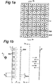
- each actuator 3(n) is associated with 9 sensors 2(m), adjacent actuators 3(n) sharing three of the sensors 2(m).
- the actuators may be controlled by other numbers of sensors.
- the actuators 3(n) and the sensors 2(m) are regularly arranged in columns and rows at equal distances. However, this is not necessary.
- Figure 1b shows a cross section through the arrangement according to figure 1a along line IB-IB.
- the same reference numbers refer to the same elements.
- the acoustic radiation of primary noise source 4 causes a pressure field p inc incident on plate 1.
- the mutual distance between two adjacent actuators is d x .
- the mutual distance between two adjacent sensors 2(m) is d sens .
- the distance between the actuator plane and the sensor plane is d.
- a reflective wall 8 which might be present in some embodiments, as will be explained below.
- the actuators 3(n) are shown to be loudspeakers producing secondary noise p s in order to reduce the primary noise p p .
- the total amount of resulting noise is measured by the sensors 2(m) which, preferably, are microphones or other pressure-sensitive devices.
- FIG. 1c shows a schematic electric diagram of the arrangement used in the invention.
- the same reference numbers refer to the same components as in figures 1a and 1b.
- Figure 1c shows four controllers 5b(i), but there may be any other desired number. They provide one or more output signals W i p which are transmitted to controllers 5a(i) of a further set of controllers which directly control the actuators 3(n). The outputs W i p of the controllers 5b(i) are also input to a supervising controller 6.
- the distribution network 10 produces detection signals v det (i) for the controllers 5a(i). Both the distribution network 10 and the controllers 5a(i) and 5b(i) may be controlled by the supervising controller 6.
- Each of the controllers 5a(i) controls one or more of the actuators 3(n) by means of control signals u i .
- the supervising controller 6 may be used for monitoring long-term behaviour of the system and for modifying control parameters of the distribution network 10 and the controllers 5a(i), 5b(i) in order to ensure overall stability of the system.
- controllers 5a(i), 5b(i), and supervising controller 6 are shown to be separate units, however, in reality they may be implemented by a single control unit performing all required functions. Controllers 5a(i), 5b(i) and 6 are preferably software driven computer units. However, optionally they may be implemented using digital circuits. Moreover, they need not be physically separated. They may be implemented as different functional sections of one single processor. On the other hand, some of the functionality of their functions may be implemented on remote processors if required. For the case of simplicity, in the description and the claims reference will only be made to processors 5a(i), 5b(i), and 6.
- FIG 1c shows a situation in which each controller 5a(i) controls one actuator 3(n), in the theoretical analysis given below, it will be assumed that each controller 5a(i) controls K actuators 3(n).
- each of the controllers 5a(i), 5b(i) tries to minimize a cost function based on sensor signals local to that controller.
- the sensor signals p result from the superposition of primary field contributions p p and the contributions p s due to N actuators.
- the latter contributions are given by Gu, where u is an N x 1 vector denoting the control signals that drive the actuators and G is an M x N matrix of transfer functions between control signals and sensor signals.
- p p p + Gu
- the present result explicitly includes the weighting factors for the error sensors.
- an iterative procedure is implemented in the system, such as the procedure described by Elliott et al. [5].
- the reader is referred to [1].
- the sensors 2(m) are pressure sensors placed in the near-field of the plate 1.
- the actuators 3(n) are loudspeakers which are assumed to operate as constant volume velocity (monopole-like) sources.
- the plate 1 is assumed to be simply supported and the incident field p inc is a plane wave arriving at a direction ⁇ of 60 degrees to the plate normal.
- the models describing the vibration of the plate 1 can be found in [7].
- the pressure p p and p s were computed with a weak form of a Fourier-type extrapolation technique in which singularities were evaluated by analytical integration [8].
- the Boundary Element method as described in [9] can also be used but the latter method is less efficient for geometries of this and larger size. Formulas for zero extrapolation distance which were used can be found in [10].
- a large distance d might be detrimental for primary signals with short correlation lengths.
- the distance d between actuator plane and the sensor plane has a considerable influence on the achievable reduction of radiated sound power. It was also found that the distance d determines the frequency above which the system has to be stabilized by increasing the value of ⁇ . A higher value of ⁇ leads to smaller reductions. The distance for instability is reached at approximately a quarter of a wavelength.
- Fig. 4 shows sound power radiated from plate 1 without control and with local control using a 48 x 48, 1 x 1 system, i.e., using a total of 48 sensors and 48 actuators, 1 sensor and 1 actuator for each independent controller, with the distance d between the actuator plane and the sensor plane as parameter.
- a positive value for ⁇ is used which makes the system just stable.
- ⁇ 0 is used. It can be seen that, for small d, reductions are increased by increasing d, particularly at low frequencies. However, the system has to be stabilized above the frequency where d equals a quarter of a wavelength. This stabilization leads to smaller reductions at high frequencies.
- the optimum for d is in the range 0.1d x ⁇ d ⁇ d x .
- the distance between the plane of actuators 3(n) and the plane of sensors 2(m) is selected carefully, i.e., in the area of the peak value of RP, preferably such that: 0.9 x RP max ⁇ RP ⁇ RP max
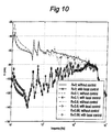
- the performance of the local control system was also investigated for the case including reflecting parallel plane 8.
- the distance of this plane 8 to the actuators was taken to be 1 m.
- the reduction which can be obtained with this configuration is shown in figure 10 and the corresponding condition numbers in figure 11. It can be seen that for reflection coefficients smaller than or equal to 0.9 the control system remains stable and leads to reasonable reductions. For a reflection coefficient of 0.99 the possible reduction above approximately 500 Hz becomes less than for lower reflection coefficients.
Landscapes
- Physics & Mathematics (AREA)
- Engineering & Computer Science (AREA)
- Acoustics & Sound (AREA)
- Multimedia (AREA)
- Soundproofing, Sound Blocking, And Sound Damping (AREA)
- Devices Affording Protection Of Roads Or Walls For Sound Insulation (AREA)
- Diaphragms For Electromechanical Transducers (AREA)
- Electromechanical Clocks (AREA)
- Finishing Walls (AREA)
- Fittings On The Vehicle Exterior For Carrying Loads, And Devices For Holding Or Mounting Articles (AREA)
Claims (6)
- Geräuschreduzierungsanordnung mit:wobei die Distanz (d) zwischen der Vielzahl von Aktuator-Mitteln (3(n)) und der Vielzahl von Sensoren (2(m)) ausgewählt ist, um eine optimierte Reduzierung der Leistung RP der Gesamtmenge an Geräuschen relativ zu den primären Geräusch innerhalb eines vorbestimmten Frequenzbandes zu erreichen,einer Vielzahl von Aktuator-Mitteln (3(n)) zum Erzeugen von Sekundärgeräuschen (ps), um Primärgeräusche (pp) zu reduzieren, die von zumindest einer Primärquelle (4) erzeugt werden,einer Vielzahl von Sensoren (2(m)) zum Erfassen der Gesamtmenge an Geräuschen, die aus den Primärgeräuschen resultieren, nachdem sie durch die Sekundärgeräusche reduziert sind, und zum Erzeugen einer Vielzahl von Sensorsignalen (p(m)),Steuereinrichtungen (5a(i), 5b(i)) zum Steuern der Aktuator-Mittel (3(n)) basierend auf den Sensorsignalen (p(m)),
dadurch gekennzeichnet, dasswobei RPmax die maximal erreichbare Reduzierung der Leistung der Gesamtmenge an Geräuschen relativ zu den Primärgeräuschen bei einer optimalen Distanz zwischen der ersten und der zweiten Fläche ist, die durch Testen erreicht wird, wobei sowohl RP als auch RPmax in Dezibel ausgedrückt sind, wobei die Vielzahl der Aktuator-Mittel in Zeilen und Spalten angeordnet sind, wobei die gegenseitigen Abstände zwischen benachbarten Spalten und die gegenseitigen Abstände zwischen benachbarten Zeilen gleich einer vorbestimmten Aktuator-Mittel-Distanz dx ist, wobei die Vielzahl von Sensoren in der gleichen Weise angeordnet sind wie die Vielzahl von Aktuator-Mitteln, wobei die Distanz d zwischen der ersten und der zweiten Fläche die nachfolgende Bedingung erfüllt:sich die Vielzahl von Aktuator-Mitteln (3(n)) in einem ersten zweidimensionalen Array in einer ersten Fläche befindet,sich die Vielzahl von Sensoren (2(m)) in einem zweiten zweidimensionalen Array in einer zweiten Fläche befindet, die im wesentlichen parallel zu der ersten Fläche angeordnet ist,die Vielzahl von Aktuator-Mitteln (3(n)) in eine Vielzahl von Untergruppen von Aktuator-Mitteln (3(n)) unterteilt ist,die Steuereinrichtungen (5a(i), 5b(ii)) eine Vielzahl von Steuerungen (5a(i), 5b(ii)) beinhalten, wobei jede Steuerung (5a(i), 5b(ii)) angeordnet ist, um Sensorsignale von einer Untergruppe der Vielzahl von Sensoren (2(m)) zu empfangen, und angeordnet ist, um eine einzelne Untergruppe von Aktuator-Mitteln (3(n)) zu steuern, unddie erste und die zweite Fläche mit einer gegenseitigen Distanz angeordnet sind, dass die Reduzierung der Leistung RP in dem folgenden Bereich liegt: - Anordnung nach Anspruch 1, bei der jede Steuerung (5a(i), 5b(ii)) angeordnet ist, um Sensorsignale von lediglich solchen Sensoren (2(m)) zu empfangen, die sich in einem bestimmten Bereich von der Steuerung (5a(i), 5b(ii)) befinden.
- Anordnung nach Anspruch 1 oder 2, bei der die Anzahl von Sensoren (2(m)) gleich der Anzahl von Aktuator-Mitteln (3(n)) und gleich der Anzahl von Steuerungen (5a(i), 5b(ii)) ist, wobei jede Steuerung (5a(i), 5b(ii)) eines von einer Vielzahl von Sensorsignalen (p(m)) als Eingangssignal empfängt und eines von einer Vielzahl von Aktuator-Mitteln (3(n)) steuert.
- Anordnung nach einem der vorhergehenden Ansprüche, bei der eine schallreflektierende Wand (8) so angeordnet ist, dass sich die zweite Fläche zwischen der ersten Fläche und der Wand (8) befindet.
- Anordnung nach einem der vorhergehenden Ansprüche, bei der ein oder mehrere Erfassungssensoren (7(r)) angeordnet sind, um die Primärgeräusche (4) zu erfassen und um ein oder mehrere Erfassungssensorsignale (Vdet(i)) für die Vielzahl von Steuerungen (5a(i), 5b(ii)) zur Verfügung zu stellen.
- Anordnung nach einem der vorhergehenden Ansprüche, bei der eine Überwachungssteuerung (6) vorgesehen ist, um in Abhängigkeit von den Sensorsignalen (p(m)) Signale zu empfangen und um das Langzeitverhalten der Anordnung zu überwachen, indem Steuerparameter der Steuerungen (5a(i), 5b(ii)) modifiziert werden, um die Gesamtstabilität der Anordnung basierend auf einem vorbestimmten Fehlerkriterium zu gewährleisten, wie zum Beispiel die Sensorsignale (p(m)).
Priority Applications (1)
| Application Number | Priority Date | Filing Date | Title |
|---|---|---|---|
| EP99971570A EP1127348B1 (de) | 1998-11-03 | 1999-10-28 | Anordnung von schallschutzplatten und verfahren zum kalibrieren derselben |
Applications Claiming Priority (4)
| Application Number | Priority Date | Filing Date | Title |
|---|---|---|---|
| EP98203699 | 1998-11-03 | ||
| EP98203699A EP0999540A1 (de) | 1998-11-03 | 1998-11-03 | Anordnung von Lärmdämpfungsplatten und Verfahren zum Kalibrieren einer solchen Plattenanordnung |
| PCT/NL1999/000664 WO2000026900A1 (en) | 1998-11-03 | 1999-10-28 | Noise reduction panel arrangement and method of calibrating such a panel arrangement |
| EP99971570A EP1127348B1 (de) | 1998-11-03 | 1999-10-28 | Anordnung von schallschutzplatten und verfahren zum kalibrieren derselben |
Publications (2)
| Publication Number | Publication Date |
|---|---|
| EP1127348A1 EP1127348A1 (de) | 2001-08-29 |
| EP1127348B1 true EP1127348B1 (de) | 2002-11-27 |
Family
ID=8234291
Family Applications (2)
| Application Number | Title | Priority Date | Filing Date |
|---|---|---|---|
| EP98203699A Withdrawn EP0999540A1 (de) | 1998-11-03 | 1998-11-03 | Anordnung von Lärmdämpfungsplatten und Verfahren zum Kalibrieren einer solchen Plattenanordnung |
| EP99971570A Expired - Lifetime EP1127348B1 (de) | 1998-11-03 | 1999-10-28 | Anordnung von schallschutzplatten und verfahren zum kalibrieren derselben |
Family Applications Before (1)
| Application Number | Title | Priority Date | Filing Date |
|---|---|---|---|
| EP98203699A Withdrawn EP0999540A1 (de) | 1998-11-03 | 1998-11-03 | Anordnung von Lärmdämpfungsplatten und Verfahren zum Kalibrieren einer solchen Plattenanordnung |
Country Status (9)
| Country | Link |
|---|---|
| US (1) | US6959092B1 (de) |
| EP (2) | EP0999540A1 (de) |
| JP (1) | JP4393713B2 (de) |
| AT (1) | ATE228703T1 (de) |
| AU (1) | AU1188600A (de) |
| DE (1) | DE69904229T2 (de) |
| DK (1) | DK1127348T3 (de) |
| ES (1) | ES2190677T3 (de) |
| WO (1) | WO2000026900A1 (de) |
Families Citing this family (12)
| Publication number | Priority date | Publication date | Assignee | Title |
|---|---|---|---|---|
| FI110896B (fi) * | 2001-05-21 | 2003-04-15 | Valtion Teknillinen | Ääntä aktiivisesti vaimentava rakenne |
| CA2440926C (en) * | 2002-09-20 | 2012-10-30 | Isao Kakuhari | Noise control apparatus |
| NL1022647C2 (nl) | 2003-02-11 | 2004-08-12 | Tno | Inrichting voor het actief reduceren van geluidstransmissie, alsmede een paneel omvattende een dergelijke inrichting. |
| US20050254664A1 (en) * | 2004-05-13 | 2005-11-17 | Kwong Wah Y | Noise cancellation methodology for electronic devices |
| WO2009076523A1 (en) * | 2007-12-11 | 2009-06-18 | Andrea Electronics Corporation | Adaptive filtering in a sensor array system |
| US9392360B2 (en) | 2007-12-11 | 2016-07-12 | Andrea Electronics Corporation | Steerable sensor array system with video input |
| US9502022B2 (en) * | 2010-09-02 | 2016-11-22 | Spatial Digital Systems, Inc. | Apparatus and method of generating quiet zone by cancellation-through-injection techniques |
| DE102015117770B4 (de) * | 2015-10-19 | 2021-05-12 | Deutsches Zentrum für Luft- und Raumfahrt e.V. | Schallreduktionssystem und Verfahren zur Schallreduzierung |
| DE102016007391A1 (de) * | 2016-06-17 | 2017-12-21 | Oaswiss AG (i. G.) | Antischallanordnung |
| EP4184504A1 (de) * | 2021-11-18 | 2023-05-24 | BAE SYSTEMS plc | System und verfahren zur aktiven akustischen steuerung |
| AU2022394783A1 (en) * | 2021-11-18 | 2024-05-23 | Bae Systems Plc | System and method for active acoustic control |
| GB2612990A (en) * | 2021-11-18 | 2023-05-24 | Bae Systems Plc | System and method |
Family Cites Families (9)
| Publication number | Priority date | Publication date | Assignee | Title |
|---|---|---|---|---|
| US4025724A (en) * | 1975-08-12 | 1977-05-24 | Westinghouse Electric Corporation | Noise cancellation apparatus |
| US4815139A (en) * | 1988-03-16 | 1989-03-21 | Nelson Industries, Inc. | Active acoustic attenuation system for higher order mode non-uniform sound field in a duct |
| US5347586A (en) * | 1992-04-28 | 1994-09-13 | Westinghouse Electric Corporation | Adaptive system for controlling noise generated by or emanating from a primary noise source |
| US5315661A (en) * | 1992-08-12 | 1994-05-24 | Noise Cancellation Technologies, Inc. | Active high transmission loss panel |
| US5416845A (en) * | 1993-04-27 | 1995-05-16 | Noise Cancellation Technologies, Inc. | Single and multiple channel block adaptive methods and apparatus for active sound and vibration control |
| US5526432A (en) * | 1993-05-21 | 1996-06-11 | Noise Cancellation Technologies, Inc. | Ducted axial fan |
| AU6635796A (en) * | 1995-07-05 | 1997-02-05 | Alumax Inc. | Method and apparatus for active noise control of high order modes in ducts |
| GB9603900D0 (en) * | 1996-02-23 | 1996-04-24 | Lotus Car | Reduction of processing in an adaptive control system having multiple inputs and multiple outputs |
| US6192133B1 (en) * | 1996-09-17 | 2001-02-20 | Kabushiki Kaisha Toshiba | Active noise control apparatus |
-
1998
- 1998-11-03 EP EP98203699A patent/EP0999540A1/de not_active Withdrawn
-
1999
- 1999-10-28 JP JP2000580201A patent/JP4393713B2/ja not_active Expired - Fee Related
- 1999-10-28 AU AU11886/00A patent/AU1188600A/en not_active Abandoned
- 1999-10-28 AT AT99971570T patent/ATE228703T1/de not_active IP Right Cessation
- 1999-10-28 DK DK99971570T patent/DK1127348T3/da active
- 1999-10-28 EP EP99971570A patent/EP1127348B1/de not_active Expired - Lifetime
- 1999-10-28 WO PCT/NL1999/000664 patent/WO2000026900A1/en not_active Ceased
- 1999-10-28 ES ES99971570T patent/ES2190677T3/es not_active Expired - Lifetime
- 1999-10-28 DE DE69904229T patent/DE69904229T2/de not_active Expired - Lifetime
- 1999-10-28 US US09/830,966 patent/US6959092B1/en not_active Expired - Fee Related
Also Published As
| Publication number | Publication date |
|---|---|
| DE69904229D1 (de) | 2003-01-09 |
| DE69904229T2 (de) | 2003-12-24 |
| DK1127348T3 (da) | 2003-03-24 |
| US6959092B1 (en) | 2005-10-25 |
| JP2002529775A (ja) | 2002-09-10 |
| WO2000026900A1 (en) | 2000-05-11 |
| EP1127348A1 (de) | 2001-08-29 |
| EP0999540A1 (de) | 2000-05-10 |
| ATE228703T1 (de) | 2002-12-15 |
| JP4393713B2 (ja) | 2010-01-06 |
| ES2190677T3 (es) | 2003-08-01 |
| AU1188600A (en) | 2000-05-22 |
Similar Documents
| Publication | Publication Date | Title |
|---|---|---|
| KR100414621B1 (ko) | 위상형센서어레이를사용하는능동노이즈제어시스템 | |
| EP1127348B1 (de) | Anordnung von schallschutzplatten und verfahren zum kalibrieren derselben | |
| Elliott | Signal processing for active control | |
| Saito et al. | Influence of modeling error on noise reduction performance of active noise control systems using filtered-x LMS algorithm | |
| EP2090137B1 (de) | Lautsprecherkonfiguration | |
| Berkhoff | Control strategies for active noise barriers using near-field error sensing | |
| Luo et al. | Implementation of multi-channel active noise control based on back-propagation mechanism | |
| Aslan et al. | Modelling and simulation of active noise control in a small room | |
| Pan et al. | Active control of sound transmission through a double-leaf partition by volume velocity cancellation | |
| Elliott et al. | Superposition of the uncertainties in acoustic responses and the robust design of active control systems | |
| Ho et al. | Time-division multiple reference approach for multiple-channel active noise control system | |
| JPH11509008A (ja) | ダクトのハイオーダーモードのアクティブノイズ制御方法及び装置 | |
| Tan et al. | Optimization of single-channel active noise control performance in a plenum window using the surface impedance approach | |
| Zhu et al. | A nonlinear sound field control method for a multi-channel parametric array loudspeaker array | |
| Romeu et al. | Active noise control in ducts in presence of standing waves. Its influence on feedback effect | |
| US11908444B2 (en) | Wave-domain approach for cancelling noise entering an aperture | |
| Sun et al. | Secondary channel estimation in spatial active noise control systems using a single moving higher order microphone | |
| Anachkova et al. | Technical aspects of physical implementation of an active noise control system: challenges and opportunities | |
| Berkhoff et al. | Efficient radiation mode sensing strategies for active structural acoustic control | |
| Takane et al. | A new theory for active suppression of reflected sound waves from the walls based on Kirchhoff-Helmholtz boundary integral equation | |
| Okamoto et al. | Verification of extension of simultaneous equations method extended to multiple-channel active noise control systems | |
| Kipersztok | Active control of broadband noise using fuzzy logic | |
| Hernandez et al. | Transmission loss of a labyrinthine acoustic metamaterial augmented with multichannel feedforward active noise control | |
| Leishman et al. | A theoretical and numerical analysis of vibration-controlled modules for use in active segmented partitions | |
| Bozcu et al. | On optimum speaker placement with a model-based approach for indoor local active noise control applications |
Legal Events
| Date | Code | Title | Description |
|---|---|---|---|
| PUAI | Public reference made under article 153(3) epc to a published international application that has entered the european phase |
Free format text: ORIGINAL CODE: 0009012 |
|
| 17P | Request for examination filed |
Effective date: 20010424 |
|
| AK | Designated contracting states |
Kind code of ref document: A1 Designated state(s): AT BE CH CY DE DK ES FI FR GB GR IE IT LI LU MC NL PT SE |
|
| AX | Request for extension of the european patent |
Free format text: AL;LT;LV;MK;RO;SI |
|
| GRAG | Despatch of communication of intention to grant |
Free format text: ORIGINAL CODE: EPIDOS AGRA |
|
| 17Q | First examination report despatched |
Effective date: 20020213 |
|
| GRAG | Despatch of communication of intention to grant |
Free format text: ORIGINAL CODE: EPIDOS AGRA |
|
| GRAH | Despatch of communication of intention to grant a patent |
Free format text: ORIGINAL CODE: EPIDOS IGRA |
|
| GRAH | Despatch of communication of intention to grant a patent |
Free format text: ORIGINAL CODE: EPIDOS IGRA |
|
| GRAA | (expected) grant |
Free format text: ORIGINAL CODE: 0009210 |
|
| AK | Designated contracting states |
Kind code of ref document: B1 Designated state(s): AT BE CH CY DE DK ES FI FR GB GR IE IT LI LU MC NL PT SE |
|
| PG25 | Lapsed in a contracting state [announced via postgrant information from national office to epo] |
Ref country code: LI Free format text: LAPSE BECAUSE OF FAILURE TO SUBMIT A TRANSLATION OF THE DESCRIPTION OR TO PAY THE FEE WITHIN THE PRESCRIBED TIME-LIMIT Effective date: 20021127 Ref country code: GR Free format text: LAPSE BECAUSE OF FAILURE TO SUBMIT A TRANSLATION OF THE DESCRIPTION OR TO PAY THE FEE WITHIN THE PRESCRIBED TIME-LIMIT Effective date: 20021127 Ref country code: FI Free format text: LAPSE BECAUSE OF FAILURE TO SUBMIT A TRANSLATION OF THE DESCRIPTION OR TO PAY THE FEE WITHIN THE PRESCRIBED TIME-LIMIT Effective date: 20021127 Ref country code: CH Free format text: LAPSE BECAUSE OF FAILURE TO SUBMIT A TRANSLATION OF THE DESCRIPTION OR TO PAY THE FEE WITHIN THE PRESCRIBED TIME-LIMIT Effective date: 20021127 Ref country code: AT Free format text: LAPSE BECAUSE OF FAILURE TO SUBMIT A TRANSLATION OF THE DESCRIPTION OR TO PAY THE FEE WITHIN THE PRESCRIBED TIME-LIMIT Effective date: 20021127 |
|
| REF | Corresponds to: |
Ref document number: 228703 Country of ref document: AT Date of ref document: 20021215 Kind code of ref document: T |
|
| REG | Reference to a national code |
Ref country code: GB Ref legal event code: FG4D |
|
| REG | Reference to a national code |
Ref country code: CH Ref legal event code: EP |
|
| REG | Reference to a national code |
Ref country code: IE Ref legal event code: FG4D |
|
| REF | Corresponds to: |
Ref document number: 69904229 Country of ref document: DE Date of ref document: 20030109 |
|
| PG25 | Lapsed in a contracting state [announced via postgrant information from national office to epo] |
Ref country code: PT Free format text: LAPSE BECAUSE OF FAILURE TO SUBMIT A TRANSLATION OF THE DESCRIPTION OR TO PAY THE FEE WITHIN THE PRESCRIBED TIME-LIMIT Effective date: 20030227 |
|
| REG | Reference to a national code |
Ref country code: DK Ref legal event code: T3 |
|
| LTIE | Lt: invalidation of european patent or patent extension |
Effective date: 20021127 |
|
| REG | Reference to a national code |
Ref country code: CH Ref legal event code: PL |
|
| ET | Fr: translation filed | ||
| REG | Reference to a national code |
Ref country code: ES Ref legal event code: FG2A Ref document number: 2190677 Country of ref document: ES Kind code of ref document: T3 |
|
| PLBE | No opposition filed within time limit |
Free format text: ORIGINAL CODE: 0009261 |
|
| STAA | Information on the status of an ep patent application or granted ep patent |
Free format text: STATUS: NO OPPOSITION FILED WITHIN TIME LIMIT |
|
| PG25 | Lapsed in a contracting state [announced via postgrant information from national office to epo] |
Ref country code: LU Free format text: LAPSE BECAUSE OF NON-PAYMENT OF DUE FEES Effective date: 20031028 Ref country code: IE Free format text: LAPSE BECAUSE OF NON-PAYMENT OF DUE FEES Effective date: 20031028 Ref country code: CY Free format text: LAPSE BECAUSE OF FAILURE TO SUBMIT A TRANSLATION OF THE DESCRIPTION OR TO PAY THE FEE WITHIN THE PRESCRIBED TIME-LIMIT Effective date: 20031028 |
|
| PG25 | Lapsed in a contracting state [announced via postgrant information from national office to epo] |
Ref country code: MC Free format text: LAPSE BECAUSE OF NON-PAYMENT OF DUE FEES Effective date: 20031031 |
|
| 26N | No opposition filed |
Effective date: 20030828 |
|
| REG | Reference to a national code |
Ref country code: IE Ref legal event code: MM4A |
|
| PGFP | Annual fee paid to national office [announced via postgrant information from national office to epo] |
Ref country code: DE Payment date: 20101022 Year of fee payment: 12 |
|
| PGFP | Annual fee paid to national office [announced via postgrant information from national office to epo] |
Ref country code: GB Payment date: 20101021 Year of fee payment: 12 Ref country code: IT Payment date: 20101026 Year of fee payment: 12 |
|
| PGFP | Annual fee paid to national office [announced via postgrant information from national office to epo] |
Ref country code: NL Payment date: 20111025 Year of fee payment: 13 Ref country code: SE Payment date: 20111021 Year of fee payment: 13 Ref country code: BE Payment date: 20111013 Year of fee payment: 13 Ref country code: DK Payment date: 20111019 Year of fee payment: 13 Ref country code: FR Payment date: 20111103 Year of fee payment: 13 Ref country code: ES Payment date: 20111026 Year of fee payment: 13 |
|
| BERE | Be: lapsed |
Owner name: NEDERLANDSE ORGANISATIE VOOR TOEGEPAST-NATUURWETEN Effective date: 20121031 |
|
| REG | Reference to a national code |
Ref country code: NL Ref legal event code: V1 Effective date: 20130501 |
|
| REG | Reference to a national code |
Ref country code: DK Ref legal event code: EBP |
|
| GBPC | Gb: european patent ceased through non-payment of renewal fee |
Effective date: 20121028 |
|
| REG | Reference to a national code |
Ref country code: FR Ref legal event code: ST Effective date: 20130628 |
|
| PG25 | Lapsed in a contracting state [announced via postgrant information from national office to epo] |
Ref country code: DE Free format text: LAPSE BECAUSE OF NON-PAYMENT OF DUE FEES Effective date: 20130501 Ref country code: BE Free format text: LAPSE BECAUSE OF NON-PAYMENT OF DUE FEES Effective date: 20121031 Ref country code: GB Free format text: LAPSE BECAUSE OF NON-PAYMENT OF DUE FEES Effective date: 20121028 Ref country code: SE Free format text: LAPSE BECAUSE OF NON-PAYMENT OF DUE FEES Effective date: 20121029 |
|
| REG | Reference to a national code |
Ref country code: DE Ref legal event code: R119 Ref document number: 69904229 Country of ref document: DE Effective date: 20130501 |
|
| PG25 | Lapsed in a contracting state [announced via postgrant information from national office to epo] |
Ref country code: NL Free format text: LAPSE BECAUSE OF NON-PAYMENT OF DUE FEES Effective date: 20130501 Ref country code: FR Free format text: LAPSE BECAUSE OF NON-PAYMENT OF DUE FEES Effective date: 20121031 Ref country code: IT Free format text: LAPSE BECAUSE OF NON-PAYMENT OF DUE FEES Effective date: 20121028 |
|
| PG25 | Lapsed in a contracting state [announced via postgrant information from national office to epo] |
Ref country code: DK Free format text: LAPSE BECAUSE OF NON-PAYMENT OF DUE FEES Effective date: 20121031 |
|
| REG | Reference to a national code |
Ref country code: ES Ref legal event code: FD2A Effective date: 20140207 |
|
| PG25 | Lapsed in a contracting state [announced via postgrant information from national office to epo] |
Ref country code: ES Free format text: LAPSE BECAUSE OF NON-PAYMENT OF DUE FEES Effective date: 20121029 |