EP1126478A1 - Ptc device and method for producing the same - Google Patents
Ptc device and method for producing the same Download PDFInfo
- Publication number
- EP1126478A1 EP1126478A1 EP00946362A EP00946362A EP1126478A1 EP 1126478 A1 EP1126478 A1 EP 1126478A1 EP 00946362 A EP00946362 A EP 00946362A EP 00946362 A EP00946362 A EP 00946362A EP 1126478 A1 EP1126478 A1 EP 1126478A1
- Authority
- EP
- European Patent Office
- Prior art keywords
- composition material
- powder
- conductive
- formed composition
- electrodes
- Prior art date
- Legal status (The legal status is an assumption and is not a legal conclusion. Google has not performed a legal analysis and makes no representation as to the accuracy of the status listed.)
- Withdrawn
Links
Images

Classifications
-
- H—ELECTRICITY
- H01—ELECTRIC ELEMENTS
- H01C—RESISTORS
- H01C7/00—Non-adjustable resistors formed as one or more layers or coatings; Non-adjustable resistors made from powdered conducting material or powdered semi-conducting material with or without insulating material
- H01C7/02—Non-adjustable resistors formed as one or more layers or coatings; Non-adjustable resistors made from powdered conducting material or powdered semi-conducting material with or without insulating material having positive temperature coefficient
-
- H—ELECTRICITY
- H01—ELECTRIC ELEMENTS
- H01C—RESISTORS
- H01C17/00—Apparatus or processes specially adapted for manufacturing resistors
- H01C17/06—Apparatus or processes specially adapted for manufacturing resistors adapted for coating resistive material on a base
- H01C17/065—Apparatus or processes specially adapted for manufacturing resistors adapted for coating resistive material on a base by thick film techniques, e.g. serigraphy
- H01C17/06506—Precursor compositions therefor, e.g. pastes, inks, glass frits
- H01C17/06513—Precursor compositions therefor, e.g. pastes, inks, glass frits characterised by the resistive component
- H01C17/0652—Precursor compositions therefor, e.g. pastes, inks, glass frits characterised by the resistive component containing carbon or carbides
-
- H—ELECTRICITY
- H01—ELECTRIC ELEMENTS
- H01C—RESISTORS
- H01C1/00—Details
- H01C1/14—Terminals or tapping points or electrodes specially adapted for resistors; Arrangements of terminals or tapping points or electrodes on resistors
- H01C1/142—Terminals or tapping points or electrodes specially adapted for resistors; Arrangements of terminals or tapping points or electrodes on resistors the terminals or tapping points being coated on the resistive element
-
- H—ELECTRICITY
- H01—ELECTRIC ELEMENTS
- H01C—RESISTORS
- H01C7/00—Non-adjustable resistors formed as one or more layers or coatings; Non-adjustable resistors made from powdered conducting material or powdered semi-conducting material with or without insulating material
- H01C7/02—Non-adjustable resistors formed as one or more layers or coatings; Non-adjustable resistors made from powdered conducting material or powdered semi-conducting material with or without insulating material having positive temperature coefficient
- H01C7/027—Non-adjustable resistors formed as one or more layers or coatings; Non-adjustable resistors made from powdered conducting material or powdered semi-conducting material with or without insulating material having positive temperature coefficient consisting of conducting or semi-conducting material dispersed in a non-conductive organic material
-
- H—ELECTRICITY
- H01—ELECTRIC ELEMENTS
- H01C—RESISTORS
- H01C7/00—Non-adjustable resistors formed as one or more layers or coatings; Non-adjustable resistors made from powdered conducting material or powdered semi-conducting material with or without insulating material
- H01C7/04—Non-adjustable resistors formed as one or more layers or coatings; Non-adjustable resistors made from powdered conducting material or powdered semi-conducting material with or without insulating material having negative temperature coefficient
- H01C7/049—Non-adjustable resistors formed as one or more layers or coatings; Non-adjustable resistors made from powdered conducting material or powdered semi-conducting material with or without insulating material having negative temperature coefficient mainly consisting of organic or organo-metal substances
-
- H—ELECTRICITY
- H05—ELECTRIC TECHNIQUES NOT OTHERWISE PROVIDED FOR
- H05B—ELECTRIC HEATING; ELECTRIC LIGHT SOURCES NOT OTHERWISE PROVIDED FOR; CIRCUIT ARRANGEMENTS FOR ELECTRIC LIGHT SOURCES, IN GENERAL
- H05B3/00—Ohmic-resistance heating
- H05B3/10—Heater elements characterised by the composition or nature of the materials or by the arrangement of the conductor
- H05B3/12—Heater elements characterised by the composition or nature of the materials or by the arrangement of the conductor characterised by the composition or nature of the conductive material
- H05B3/14—Heater elements characterised by the composition or nature of the materials or by the arrangement of the conductor characterised by the composition or nature of the conductive material the material being non-metallic
- H05B3/146—Conductive polymers, e.g. polyethylene, thermoplastics
Definitions
- the present invention relates to a PTC element composed of a conductive composition material (hereinafter referred to PTC composition material) showing positive temperature properties, so-called PTC (Positive Temperature Coefficient) properties that mean its resistance value suddenly rises when a fixed temperature (hereinafter referred to as a switching temperature) region is reached.
- PTC composition material a conductive composition material showing positive temperature properties
- PTC Positive Temperature Coefficient
- PTC elements are used as an protective element of electrical circuits to prevent over-current that flows when an abnormal state is happen in these apparatus.
- a PTC element is composed of a PTC composition material obtained by blending and kneading conductive powder with a crystalline polymer and of electrodes formed on said PTC composition material, and shows sudden increase in its resistance value when the switching temperature is reached. That is, a PTC composition material produces heat in accordance with joule heat (I 2 R heat) generated by resistance value R peculiar to the material and electric current value I flowed in the element through the above-mentioned electrodes. Like this, if relatively high current flows in the PTC composition material, heat generation occurs to make its resistance value increase.
- PTC elements are used as a sheet heat generation material using the generation of above-mentioned joule heat, an over-current protective element using increase in resistance value, and the like.
- the contact resistance value between the PTC composition material and the electrode becomes high and good ohmic contact cannot be obtained.
- the PTC composition material relating to this first former example because resistance value becomes high at room temperature, it is difficult to use the PTC composition material as an over-current protective element and the like.
- the adhesion between the PTC composition material and the electrodes is insufficient, resistance value increases greatly in cases where the PTC element is repeatedly operated (turning on electricity).
- the contact resistance value between the PTC composition material and the electrode becomes lower than that in the above-mentioned first former example and the adhesion between the two also becomes better, but it is not yet reached to obtain good ohmic contact.
- the adhesion between the PTC composition material and the plated coat is not sufficient and the contact resistance value between the two becomes high. And great increase in resistance value due to repeated operation is also inevitable.
- a PTC composition material is a complex material of an organic matter and an inorganic substance
- the composition material is greatly affected by environmental humidity during being stocked and used and the change of its resistance becomes to be great as the passage of time when switching operation is repeatedly carried out.
- it is needed to fill up the conductive filler in large amount.
- the resulting composition material is easily affected by environmental humidity during being stocked and used.
- the element itself becomes to be apt to peel off from the electrodes as the passage of time when switching operation is repeatedly carried out, the composition material could not obtain sufficient reliability for the long time usage (repeated usage).
- conductive powder filler composed of at least one out of TiC, WC, W 2 C, ZrC, VC, NbC, TaC, and Mo 2 C is blended and kneaded with a crystalline polymer component by 35 to 60 volume percent to form a formed composition material, a conductive material is pressure sealed and buried so that the material is partly exposed from the surface of said formed composition material, and then electrodes are formed by plating on said surface of said formed composition material.
- a PTC element can be obtained, and the PTC element is characterized in that it has a formed composition material in which conductive powder filler is blended and kneaded with a crystalline polymer component by 35 to 60 volume percent, a conductive material pressure sealed and buried so that the material is partly exposed from the surface of said formed composition material, and electrodes formed by plating on said surface of said formed composition material, and in that at least one out of TiC, WC, W 2 C, ZrC, VC, NbC, TaC, and Mo 2 C is used as said conductive powder filler.
- Said conductive material is preferable to include Ni powder, Al powder, Cu powder, Fe powder, Ag powder, or graphite powder.
- a formed composition material by blending and kneading said conductive powder filler with a crystalline polymer component by 45 to 60 volume percent.
- a production method of a PTC element that is characterized in that the method has a process in which a formed composition material is obtained by means of blending and kneading at least one out of TiC, WC, W 2 C, ZrC, VC, NbC, TaC, and Mo 2 C with a crystalline polymer component by 35 to 60 volume percent as a conductive powder filler, a process in which after coated said formed composition material with a conductive paste containing a conductive powder, said conductive powder is treated by pressure sealing to bury said conductive powder so that part of said conductive powder is exposed from the surface of said formed composition material, and a process in which said surface of said formed composition material is plated to form electrodes.
- Ni powder, Al powder, Cu powder, Fe powder, Ag powder, or graphite powder is used as said conductive powder.
- said conductive powder filler is blended and kneaded with a crystalline polymer component by 45 to 60 volume percent to form a formed composition material.
- conductive powder filler composed of at least one out of TiC, WC, W 2 C, ZrC, VC, NbC, TaC, and Mo 2 C is blended and kneaded with a crystalline polymer component by 35 to 60 volume percent to form a formed composition material, a conductive material is pressure sealed and buried so that the material is partly exposed from the surface of said formed composition material, then electrodes are formed by plating on said surface of said formed composition material, moreover, a steam barrier layer is formed in the part other than said plated electrode of the PCT element.
- a PTC element that is characterized in that the PTC element has a formed composition material in which a conductive powder filler using at least one out of TiC, WC, W 2 C, ZrC, VC, NbC, TaC, and Mo 2 C is blended and kneaded with a crystalline polymer component by 35 to 60 volume percent, a conductive material which is pressure sealed and buried so that it is partly exposed from the surface of said formed composition material, electrodes formed by plating on said surface of said formed composition material, and a steam barrier layer formed in the part other than said plated electrode.
- said crystalline polymer component is a polymer alloy in which at least one kind of thermoplastic polymer is mixed.
- a production method of a PTC element that is characterized in that the method has a process in which a formed composition material is obtained by means of blending and kneading at least one out of TiC, WC, W 2 C, ZrC, VC, NbC, TaC, and Mo 2 C with a crystalline polymer component by 35 to 60 volume percent as a conductive powder filler, a process in which after coated said formed composition material with a conductive paste containing a conductive powder, said conductive powder is treated by pressure sealing to bury said conductive powder so that part of said conductive powder is exposed from the surface of said formed composition material, a process in which said surface of said formed composition material is plated to form electrodes, and a process in which a steam barrier treatment is carried out in the part other than said plated electrodes.
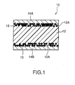
- PTC element 10 related to the first embodiment of the present invention has formed composition material 12 in which conductive powder filler (not shown in the figure) was blended and kneaded with a crystalline polymer component by 35 to 60 volume percent, conductive material 13 pressure sealed and buried so that it is partly exposed from surface 12A of formed composition material 12, and electrodes 14A and 14B formed by means of plate treatment on surface 12A of formed composition material 12.
- conductive powder filler one or two kinds or more out of TiC, WC, W 2 C, ZrC, VC, NbC, TaC, and Mo 2 C can be used.
- conductive material 13 is preferable to include Ni powder, Al powder, Cu powder, Fe powder, Ag powder, or graphite powder.
- crystalline high-density polyethylene having softening point of about 130°C as a polymer component and conductive powder filler of 1 to 5 ⁇ m in particle size were blended and kneaded on a roller mill heated about 140 to 200°C so that the content of the conductive powder was 35 to 60 volume percent, and kneaded polymer material was obtained.
- one or two kinds or more out of TiC, WC, W 2 C, ZrC, VC, NbC, TaC, and Mo 2 C can be used as conductive, powder [See Fig. 2(a)].
- test piece of 1 cm 2 in area was punched out from the Ni plated sheet obtained as mentioned above and used as a sample for assay (hereinafter, this sample for assay is referred to as "the example” ). Furthermore, as conductive powder buried in the sheet by pressure sealing, it is acceptable to use Al powder, Cu powder, Fe powder, Ag powder, or graphite powder, as well as Ni powder.
- comparative sample 1 was prepared as in the following (hereinafter, this comparative sample is referred to as "comparative example 1")
- comparative sample 2 was prepared as in the following (hereinafter, this comparative sample is referred to as "comparative example 2" ). Also in this comparative example 2, the same treatment as in the above-mentioned example was carried out until kneaded polymer material was sheeted. After that, metal plates, their one side to be contacted with the kneaded material sheet (one side of each metal plate) were roughened with electrolyte, were agglutinated on both sides of the kneaded material sheet by heat pressing at temperatures of about 140 to 200°C to form electrodes, And, a test piece of 1 cm 2 in area was punched out from this sheet and a PTC element was obtained (comparative example 2).
- comparative sample 3 was prepared as in the following (hereinafter, this comparative sample is referred to as "comparative example 3" ). Also in this comparative example 3, the same treatment as in the above-mentioned example was carried out until kneaded polymer material was sheeted. After that, the kneaded material sheet was defatted and then Ni electroless plating was carried out on the sheet to form electrodes. And, a test piece of 1 cm 2 in area was punched out from this sheet and a PTC element was obtained (comparative example 3).
- comparative sample 4 was prepared as in the following (hereinafter, this comparative sample is referred to as "comparative example 4" ).
- Crystalline high-density polyethylene having softening point of about 130°C as a polymer component and conductive powder of 1 to 5 ⁇ m in particle size were blended and kneaded on a roller mill heated about 140 to 200°C so that the content of the conductive powder was 34 volume percent, and kneaded polymer material was obtained.
- TiC, WC, W 2 C, ZrC, VC, NbC, TaC, and Mo 2 C was used as conductive powder.
- the same treatment as in the above-mentioned example was carried out, then a test piece of 1 cm 2 in area was punched out from this sheet and a PTC element was obtained (comparative example 4).
- Characteristic properties were tested on the example and comparative example 1 to 3 obtained as mentioned above.
- target properties of the PTC element were decided as follows: bonding strength of the electrode is 500 gf/cm 2 or more, which means sufficient reliability as an electrode, resistance at room temperature is 2 ⁇ ⁇ cm or less, and the ratio of resistance value after resistance value was suddenly increased to temperatures (after switching) to resistance value at room temperature (after switching R/room temperature R) is 10 4 or more, which means that the PTC element sufficiently operates as over-current protective element and can be fully used as a sheet heater. Further, the target of resistance value at room temperature in cases of repeated switching of the PTC was decided to be 2 ⁇ ⁇ cm or less even after 50 times switching.
- the bonding strength of electrodes in the example was higher than those in comparative example 1 where a metal plate not roughened was used as electrodes and comparative example 3 where only plating was performed to form electrodes, and was about the same value as that in comparative example 2 where a roughened metal plate was used as electrodes.
- the bonding strength of electrodes of the example was confirmed to be more than 500 gf/cm 2 , the value is possible to sufficiently holding reliability as an electrode.
- resistivity at room temperature was confirmed to be as low as target values of 2 ⁇ ⁇ cm or less.
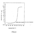
- resistivity at room temperature is as low as target value of 2 ⁇ ⁇ cm or less and the curve of temperature-resistivity greatly increases at temperatures roughly corresponding to the softening point (about 130°C) of crystalline high-density polyethylene used in the example.
- the ratio of resistance value after resistance value was suddenly increased to temperatures (after switching) to resistance value at room temperature (after switching R/room temperature R) is higher than 10 8 and greatly exceeds the target value of 10 4 which means that the PTC element sufficiently operates as over-current protective element and can be fully used as a sheet heater.
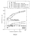
- initial resistivity at room temperature was as low as target value of 2 ⁇ cm or less and continued to keep target values of 2 ⁇ ⁇ cm or less after repeated current flow. And after several times of repeated current flow, increase in resistivity at room temperature was found to be saturated.
- the filling amount of conductive powder is less than 35 volume percent, as mentioned above, stability to repeated current flow decreases and resistivity at room temperature may exceed the target value of 2 ⁇ ⁇ cm according as the frequency of operations.
- the filling amount of conductive powder is more than 60 volume percent, it will be actually difficult to manufacture elements because of decrease in their manufacturing efficiency.
- a conductive material was pressure sealed and buried on the surface of a formed composition material, in which conductive powder filler was blended and kneaded with a crystalline polymer component by 35 to 60 volume percent, so that the conductive material is partly exposed, and electrodes were formed by plating treatment on the surface of the formed composition material where the conductive material was partly exposed, and further, as conductive powder filler, at least one out of TiC, WC, W 2 C, ZrC, VC, NbC, TaC, and Mo 2 C was used. Consequently, the adhesion between the PTC composition material and electrodes becomes good and the contact resistance between the two can be lowered. And it is possible to obtain a PTC element excellent in stability to repeated current flow.
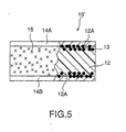
- Fig. 5 is a partial sectional view showing the PTC element related to the second embodiment of the present invention.
- the PTC element 10 in the embodiment has formed composition material 12, conductive material 13 which is pressure sealed and buried so that the material is partly exposed from the surface 12A of formed composition material 12, and electrodes 14A and 14B formed by plating treatment on the surface 12A of formed composition material 12. And on the part where formed composition material 12 other than (plated) electrodes 14A and 14B is exposed, steam barrier layer 16 is coated.
- composition material 12 is quite the same as that in the above-mentioned embodiment 1 and was formed as follows: conductive powder filler using at least one out of TiC, WC, W 2 C, ZrC, VC, NbC, TaC, and Mo 2 C was blended and kneaded with a crystalline polymer component by 35 to 60 volume percent and then the mixture was formed.
- the crystalline polymer component in formed composition material 12 is composed of a polymer alloy in which one kind or two or more kinds of thermoplastic polymers, for example, modified polyethylene or modified polypropylene, are mixed.
- Nickel (Ni) foil is used in each of electrode 14A and 14B.
- Steam barrier layer 16 is formed by conducting steam barrier treatment, for example, as mention later, such as coating with PVDC latex and others.
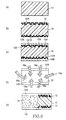
- Fig. 6 indicates drawings to explain the production method of the PTC element of the example, (a) shows the formed composition material, (b) shows a state in which a conductive material is pressure sealed and buried so that the material is partly exposed from the surface of the formed composition material, (c) shows a state in which electrodes are formed by plating treatment on the formed composition material, (d) shows steam barrier treatment, and (e) shows the PTC element treated with steam barrier treatment, respectively.
- steam barrier layer 16 was formed by coating PVCD latex 16a on the part except for plated electrodes (nickel foil) 14A and 14B in formed composition material 12, that is, on part 12 C where the surface of formed composition material 12 is exposed, as shown in Fig. 6 (d), and PTC (resistant) element 10 of the example shown Fig. 6 (e) was consequently made.
- high-density polyethylene resin was used as a main component of the formed composition material, but the main component is not limited to the resin.
- main components of formed composition materials polypropylene type, low-density polyethylene type and other type resins can be used, as well as high-density polyethylene resin.
- steam barrier was formed by coating with PVCD latex, but in addition to this, methods of steam barrier treatment using substances with low steam permeability, for example, polyvinylidene chloride and the like are considered.
- a conductive material is pressure sealed and buried so that part of the conductive material is exposed, and the surface of the formed composition material with partly exposed conductive material is plated to form electrodes.
- at least one out of TiC, WC, W 2 C, ZrC, VC, NbC, TaC, and Mo 2 C is used as conductive powder filler. Consequently, the adhesion between the PTC composition material and the electrodes becomes good and contact resistance value between the two can be reduced. And a PTC element with excellent stability to repeated turning on electricity and its production. method can be obtained.
- the PTC element and its production method of the above-mentioned first embodiment it is further possible to effectively prevent the PTC element itself from peeling from electrodes due to the effect of environmental humidity. And a high reliable PTC element with good stability and reproducibility to repeated use and its production method can be provided.
Abstract
Description
- The present invention relates to a PTC element composed of a conductive composition material (hereinafter referred to PTC composition material) showing positive temperature properties, so-called PTC (Positive Temperature Coefficient) properties that mean its resistance value suddenly rises when a fixed temperature (hereinafter referred to as a switching temperature) region is reached.
- Up to now, being employed in electrical equipment and electronic equipment as well as secondary batteries, PTC elements are used as an protective element of electrical circuits to prevent over-current that flows when an abnormal state is happen in these apparatus.
- In general, a PTC element is composed of a PTC composition material obtained by blending and kneading conductive powder with a crystalline polymer and of electrodes formed on said PTC composition material, and shows sudden increase in its resistance value when the switching temperature is reached. That is, a PTC composition material produces heat in accordance with joule heat (I2R heat) generated by resistance value R peculiar to the material and electric current value I flowed in the element through the above-mentioned electrodes. Like this, if relatively high current flows in the PTC composition material, heat generation occurs to make its resistance value increase. In general, PTC elements are used as a sheet heat generation material using the generation of above-mentioned joule heat, an over-current protective element using increase in resistance value, and the like.
- As former PTC elements, especially from the viewpoint of the method of forming their electrodes, for example, the following 3 elements are known.
- First, an element in which the surface of a metal plate of stainless steel, or nickel and the like is agglutinated on the surface of a PTC composition material and the metal plate is used as electrodes.
- Second, an element in which in order to improve the adhesion of such electrodes and a PTC composition material, the surface of a metal plate is further roughened physically or chemically and the roughened surface is agglutinated on the surface of a PTC composition material to make electrodes.
- Third, an element in which a PTC composition material is directly metal plated to make electrodes.
- However, in the first former example in which electrodes are made by agglutinated the surface of a metal plate on the surface of a PTC composition material, the contact resistance value between the PTC composition material and the electrode becomes high and good ohmic contact cannot be obtained. As a result, in the PTC composition material relating to this first former example, because resistance value becomes high at room temperature, it is difficult to use the PTC composition material as an over-current protective element and the like. In addition, because the adhesion between the PTC composition material and the electrodes is insufficient, resistance value increases greatly in cases where the PTC element is repeatedly operated (turning on electricity).
- Moreover, in the second former example in which the surface of a metal plate roughened physically or chemically is agglutinated on the surface of a PTC composition material to make electrodes, the contact resistance value between the PTC composition material and the electrode becomes lower than that in the above-mentioned first former example and the adhesion between the two also becomes better, but it is not yet reached to obtain good ohmic contact. In association with the second former example, it is also proposed to increase the amount of conductive powder to be dispersed in a PTC composition material up to 45 volume percent or more in order to improve the stability of the PTC element against its repeated operation as well as lowering its resistance value at room temperature. However, also in this case, it is difficult not only to lower the resistance value at room temperature to a certain value or less but also to retard completely the increase in the resistance value for every operation when operations are repeated.
- Furthermore, in the third former example in which a PTC composition material is directly metal plated to make electrodes, the adhesion between the PTC composition material and the plated coat is not sufficient and the contact resistance value between the two becomes high. And great increase in resistance value due to repeated operation is also inevitable.
- As a controversial point common in the first to third former examples, there is a problem that resistance values at room temperature increase due to the deterioration of PTC composition materials themselves in cases where those PTC elements are repeatedly operated. As a cause for this problem, it is presumed that crystalline polymer components deteriorate due to heat shock for every operation when operations are repeated.
- On the other hand, since a PTC composition material is a complex material of an organic matter and an inorganic substance, there is also such a problem that the composition material is greatly affected by environmental humidity during being stocked and used and the change of its resistance becomes to be great as the passage of time when switching operation is repeatedly carried out. In particular, in order to obtain an element having good conductivity in a PTC composition material using metallic conductive filler, it is needed to fill up the conductive filler in large amount. But when a conductive filler of inorganic substance is filled in large amount, the resulting composition material is easily affected by environmental humidity during being stocked and used. And, as mentioned above, since the element itself becomes to be apt to peel off from the electrodes as the passage of time when switching operation is repeatedly carried out, the composition material could not obtain sufficient reliability for the long time usage (repeated usage).
- It is therefore the first object of the present invention to provide a PTC element that is excellent in stability to repeated operation and has sufficient adhesion with the PTC composition material and electrodes with low contact resistance value, and to provide its production method.
- It is the second object of the present invention, in a PTC element and its production method to achieve the above-mentioned first object, to provide a PTC element that can effectively prevent the PTC element itself from peeling off from the electrodes due to the effect of environmental humidity and is good in stability and reproducibility to repeated usage and has a high reliability.
- In order to achieve the above-mentioned first object, in the PTC element and its production method of the present invention, conductive powder filler composed of at least one out of TiC, WC, W2C, ZrC, VC, NbC, TaC, and Mo2C is blended and kneaded with a crystalline polymer component by 35 to 60 volume percent to form a formed composition material, a conductive material is pressure sealed and buried so that the material is partly exposed from the surface of said formed composition material, and then electrodes are formed by plating on said surface of said formed composition material.
- That is, according to an aspect of the present invention, a PTC element can be obtained, and the PTC element is characterized in that it has a formed composition material in which conductive powder filler is blended and kneaded with a crystalline polymer component by 35 to 60 volume percent, a conductive material pressure sealed and buried so that the material is partly exposed from the surface of said formed composition material, and electrodes formed by plating on said surface of said formed composition material, and in that at least one out of TiC, WC, W2C, ZrC, VC, NbC, TaC, and Mo2C is used as said conductive powder filler.
- Said conductive material is preferable to include Ni powder, Al powder, Cu powder, Fe powder, Ag powder, or graphite powder.
- And, it is preferable to form a formed composition material by blending and kneading said conductive powder filler with a crystalline polymer component by 45 to 60 volume percent.
- Further, according to another aspect of the present invention, it is possible to obtain a production method of a PTC element that is characterized in that the method has a process in which a formed composition material is obtained by means of blending and kneading at least one out of TiC, WC, W2C, ZrC, VC, NbC, TaC, and Mo2C with a crystalline polymer component by 35 to 60 volume percent as a conductive powder filler, a process in which after coated said formed composition material with a conductive paste containing a conductive powder, said conductive powder is treated by pressure sealing to bury said conductive powder so that part of said conductive powder is exposed from the surface of said formed composition material, and a process in which said surface of said formed composition material is plated to form electrodes.
- It is preferable that Ni powder, Al powder, Cu powder, Fe powder, Ag powder, or graphite powder is used as said conductive powder.
- And, it is preferable that said conductive powder filler is blended and kneaded with a crystalline polymer component by 45 to 60 volume percent to form a formed composition material.
- In order to achieve the above-mentioned second object, in the PTC element and its production method of the present invention, conductive powder filler composed of at least one out of TiC, WC, W2C, ZrC, VC, NbC, TaC, and Mo2C is blended and kneaded with a crystalline polymer component by 35 to 60 volume percent to form a formed composition material, a conductive material is pressure sealed and buried so that the material is partly exposed from the surface of said formed composition material, then electrodes are formed by plating on said surface of said formed composition material, moreover, a steam barrier layer is formed in the part other than said plated electrode of the PCT element.
- That is, according to further another aspect of the present invention, it is possible to obtain a PTC element that is characterized in that the PTC element has a formed composition material in which a conductive powder filler using at least one out of TiC, WC, W2C, ZrC, VC, NbC, TaC, and Mo2C is blended and kneaded with a crystalline polymer component by 35 to 60 volume percent, a conductive material which is pressure sealed and buried so that it is partly exposed from the surface of said formed composition material, electrodes formed by plating on said surface of said formed composition material, and a steam barrier layer formed in the part other than said plated electrode.
- It is preferable that said crystalline polymer component is a polymer alloy in which at least one kind of thermoplastic polymer is mixed.
- Moreover, according to a further different aspect of the present invention, it is possible to obtain a production method of a PTC element that is characterized in that the method has a process in which a formed composition material is obtained by means of blending and kneading at least one out of TiC, WC, W2C, ZrC, VC, NbC, TaC, and Mo2C with a crystalline polymer component by 35 to 60 volume percent as a conductive powder filler, a process in which after coated said formed composition material with a conductive paste containing a conductive powder, said conductive powder is treated by pressure sealing to bury said conductive powder so that part of said conductive powder is exposed from the surface of said formed composition material, a process in which said surface of said formed composition material is plated to form electrodes, and a process in which a steam barrier treatment is carried out in the part other than said plated electrodes.
-
- Fig. 1 is a sectional view showing the PTC element related to the first embodiment of the present invention;
- Fig. 2 indicates drawings to explain the production method of the PTC element related to the first embodiment of the present invention, they are sectional views showing (a) the formed composition material, (b) a state where a conductive material is pressure sealed and buried so that it is partly exposed from the surface of the formed composition material, and (c) a state where said formed composition material is plated to form electrodes, respectively;
- Fig. 3 is a graphical representation showing the temperature - resistivity property in a PCT element in an example of the present invention;
- Fig. 4 is a graphical representation showing resistivity properties after current of 10A (50V) is repeatedly impressed on the PTC element of the first example of the present invention and on the PTC elements of comparative examples;
- Fig. 5 is a partial sectional view showing the PTC element related to the second embodiment of the present invention; and
- Fig. 6 indicates drawings to explain the production method of the PTC element related to the second embodiment of the present invention, (a) is a sectional view of a formed composition material, (b) is a sectional view showing a state where the conductive material is pressure sealed and buried so that it is partly exposed from the surface of the formed composition material, (c) is a sectional view showing a state where the composition material is plated to form electrodes, (d) is a schematic view showing steam barrier treatment, (e) is a partial sectional view showing the PTC element after steam barrier treatment is performed, respectively.
-
- The present invention will be explained in more detail according to attached drawings.
- At first, referring to Figs from 1 to 4, the PTC element and its production method related to the first embodiment of the present invention is explained.
- As shown in Fig. 1,
PTC element 10 related to the first embodiment of the present invention has formedcomposition material 12 in which conductive powder filler (not shown in the figure) was blended and kneaded with a crystalline polymer component by 35 to 60 volume percent,conductive material 13 pressure sealed and buried so that it is partly exposed fromsurface 12A of formedcomposition material 12, andelectrodes surface 12A of formedcomposition material 12. As conductive powder filler, one or two kinds or more out of TiC, WC, W2C, ZrC, VC, NbC, TaC, and Mo2C can be used. Still more,conductive material 13 is preferable to include Ni powder, Al powder, Cu powder, Fe powder, Ag powder, or graphite powder. - In order to produce
PTC element 10 in embodiments of the present invention, it is necessary to have at least a process in which as shown in Fig. 2 (a), at least one out of TiC, WC, W2C, ZrC, VC, NbC, TaC, and Mo2C is blended and kneaded with a crystalline polymer component by 35 to 60 volume percent as a conductive powder filler to obtain formedcomposition material 12, a process in which after conductive paste containingconductive powder 13 is coated onsurface 12A of formedcomposition material 12, pressure sealing treatment ofconductive powder 13 is carried out and, as shown in Fig. 2 (b),conductive powder 13 is buried so that it is partly exposed fromsurface 12A of formed composition material, and a process in which as shown in Fig. 2 (c),surface 12A of formedcomposition material 12 is plated to form (plated)electrodes - And, an example of the production methods of above-mentioned
PTC element 10 will be explained more concretely. - At first, crystalline high-density polyethylene having softening point of about 130°C as a polymer component and conductive powder filler of 1 to 5 µ m in particle size were blended and kneaded on a roller mill heated about 140 to 200°C so that the content of the conductive powder was 35 to 60 volume percent, and kneaded polymer material was obtained. Further, for example, one or two kinds or more out of TiC, WC, W2C, ZrC, VC, NbC, TaC, and Mo2C can be used as conductive, powder [See Fig. 2(a)].
- Next, after the above-mentioned kneaded high polymer material was powdered, the powder was press molded to make a sheet and a sheet of kneaded polymer material was obtained as a result. Then, both sides of the kneaded polymer material were coated with conductive paste composed of Ni powder, polyvinylbutyral, and a solvent and dried at room temperature for 5 hours or more to make a dried sheet. This dried sheet was pressed at temperatures of about 140 to 200°C for about 5 to 15 minutes to make Ni powder pressure sealed. As a result, a PTC composition material sheet, in which most of Ni powder was buried in the sheet and part of the powder was exposed on the surface of the sheet, was obtained [ See Fig. 2 (b)].
- After the PTC composition material sheet pressure sealed as mentioned above was defatted in succession, Ni electroless plating was carried out on the sheet to form electrodes [See Fig. 2(c)] .
- A test piece of 1 cm2 in area was punched out from the Ni plated sheet obtained as mentioned above and used as a sample for assay (hereinafter, this sample for assay is referred to as " the example" ). Furthermore, as conductive powder buried in the sheet by pressure sealing, it is acceptable to use Al powder, Cu powder, Fe powder, Ag powder, or graphite powder, as well as Ni powder.
- Then, to compare with the example,
comparative sample 1 was prepared as in the following (hereinafter, this comparative sample is referred to as "comparative example 1") - In this comparative example 1, the same treatment as in above-mentioned example was carried out until the kneaded polymer material was sheeted. After that, metal plates were agglutinated on both sides of the kneaded material sheet by heat pressing at temperatures of about 140 to 200°C to form electrodes. And, a test piece of 1 cm2 in area was punched out from this sheet and a PTC element was obtained (Comparative example 1).
- Moreover,
comparative sample 2 was prepared as in the following (hereinafter, this comparative sample is referred to as "comparative example 2" ). Also in this comparative example 2, the same treatment as in the above-mentioned example was carried out until kneaded polymer material was sheeted. After that, metal plates, their one side to be contacted with the kneaded material sheet (one side of each metal plate) were roughened with electrolyte, were agglutinated on both sides of the kneaded material sheet by heat pressing at temperatures of about 140 to 200°C to form electrodes, And, a test piece of 1 cm2 in area was punched out from this sheet and a PTC element was obtained (comparative example 2). - Further,
comparative sample 3 was prepared as in the following (hereinafter, this comparative sample is referred to as "comparative example 3" ). Also in this comparative example 3, the same treatment as in the above-mentioned example was carried out until kneaded polymer material was sheeted. After that, the kneaded material sheet was defatted and then Ni electroless plating was carried out on the sheet to form electrodes. And, a test piece of 1 cm2 in area was punched out from this sheet and a PTC element was obtained (comparative example 3). - Furthermore,
comparative sample 4 was prepared as in the following (hereinafter, this comparative sample is referred to as "comparative example 4" ). Crystalline high-density polyethylene having softening point of about 130°C as a polymer component and conductive powder of 1 to 5µm in particle size were blended and kneaded on a roller mill heated about 140 to 200°C so that the content of the conductive powder was 34 volume percent, and kneaded polymer material was obtained. Still more, TiC, WC, W2C, ZrC, VC, NbC, TaC, and Mo2C was used as conductive powder. The same treatment as in the above-mentioned example was carried out, then a test piece of 1 cm2 in area was punched out from this sheet and a PTC element was obtained (comparative example 4). - Characteristic properties were tested on the example and comparative example 1 to 3 obtained as mentioned above. Well, as target properties of the PTC element were decided as follows: bonding strength of the electrode is 500 gf/cm2 or more, which means sufficient reliability as an electrode, resistance at room temperature is 2 Ω · cm or less, and the ratio of resistance value after resistance value was suddenly increased to temperatures (after switching) to resistance value at room temperature (after switching R/room temperature R) is 104 or more, which means that the PTC element sufficiently operates as over-current protective element and can be fully used as a sheet heater. Further, the target of resistance value at room temperature in cases of repeated switching of the PTC was decided to be 2 Ω · cm or less even after 50 times switching.
- At first, lead wires were connected by soldering on the surfaces of electrodes of PTC elements (example and comparative example 1 to 3) obtained as mentioned above and surroundings of the electrodes were coated with epoxy resin. Samples for measuring bonding strength were thus prepared. Then, bonding strength of each electrode was measured by pulling a lead wire of each sample for measuring corresponding to the example and comparative example 1 to 3. Measurements are shown in Table 1.
Bonding strength of electrodes Sample Bonding strength (gf/cm2) Example 800 to 2300 Comparative example 1(Metal plate) 25 to 150 Comparative example 2 (Roughened metal plate) 850 to 2400 Comparative example 3 (Plating only) 30 to 170 - As clearly shown in Table 1, the bonding strength of electrodes in the example was higher than those in comparative example 1 where a metal plate not roughened was used as electrodes and comparative example 3 where only plating was performed to form electrodes, and was about the same value as that in comparative example 2 where a roughened metal plate was used as electrodes. And the bonding strength of electrodes of the example was confirmed to be more than 500 gf/cm2, the value is possible to sufficiently holding reliability as an electrode.
- In the next place, resistance values at room temperature after 500 times of switching were measured on example and comparative example 1 to 3. Measurements are shown in Table 2. Well, a digital multimeter with direct current 4 short needles was used for measuring resistivity at room temperature.
Resistivity at room temperature Sample Resistivity at room temperature (Ω · cm) Example (TiC) 0.4 Example (WC) 0.5 Example (W2C) 0.4 Example (ZrC) 0.4 Example (VC) 0.6 Example (NbC) 0.5 Example (TaC) 0.4 Example (Mo2C) 0.5 Comparative example 1 (Metal plate) 110.0 Comparative example 2 (Roughened metal plate) 1.3 Comparative example 3 (Plating only) 320.0 - As clearly shown in Table 2, in the examples, in cases where any of TiC, WC, W2C, ZrC, VC, NbC, TaC, and Mo2C is used, resistivity at room temperature was confirmed to be as low as target values of 2Ω · cm or less.
- To the contrary, in comparative example 1 where a metal plate not roughened was used as electrodes and comparative example 3 where only plating was performed to form electrodes, resistivity at room temperature was high, and it was found that it was quite difficult to obtain target values of 2 Ω · cm or less. It is considered that this is because of high contact resistance between electrodes and kneaded material sheets. On the other hand, in comparative example 2 where a roughened metal plate was used as electrodes, resistivity at room temperature was found to be as low as target values of 2 Ω · cm or less but higher than those in the examples. It is considered that this is because ohmic contact between the electrodes and the kneaded material sheet is not so good as in the examples.
- In the next place, a relationship between temperature and resistivity was measured on example. Measurements are shown in Fig. 3. Well, measurements were made by using a four short needle method in an oil bath and a digital multimeter was used to determine resistivity.
- As clearly shown in Fig. 3, in the example, resistivity at room temperature is as low as target value of 2 Ω · cm or less and the curve of temperature-resistivity greatly increases at temperatures roughly corresponding to the softening point (about 130°C) of crystalline high-density polyethylene used in the example. And the ratio of resistance value after resistance value was suddenly increased to temperatures (after switching) to resistance value at room temperature (after switching R/room temperature R) is higher than 108 and greatly exceeds the target value of 104 which means that the PTC element sufficiently operates as over-current protective element and can be fully used as a sheet heater.
- Moreover, current of 10A (50V) was repeatedly caused to flow through PTC elements (in the example and comparative example 1 to 4) obtained as mentioned above, respectively, and the changes of resistivity after operations were measured. Measurements are shown in Fig. 4.
- As clearly shown in Fig. 4, in the example, initial resistivity at room temperature was as low as target value of 2 Ω cm or less and continued to keep target values of 2Ω · cm or less after repeated current flow. And after several times of repeated current flow, increase in resistivity at room temperature was found to be saturated.
- To the contrary, in comparative example 1 where a metal plate not roughened was used as electrodes and comparative example 3 where only plating was performed to form electrodes, initial resistivity at room temperature greatly exceeded the target value of 2 Ω · cm, and further, it is known that resistivity at room temperature greatly increases nearly in proportion to repeated current flow. On the other hand, in comparative example 2 where a roughened metal plate was used as electrodes, initial resistivity at room temperature was as low as target values of 2Ω · cm or less but exceeded the target value of 2 Ω cm by repeated current flow, and no saturation is seen in the increase in resistivity at room temperature.
- Furthermore, in comparative example 4 where conductive powder was 34 volume percent, initial resistivity at room temperature was as low as target values of 2 Ω · cm or less but exceeded the target value of 2 Ω · cm by repeated current flow, and it was found that stability to repeated current flow would not be obtained.
- Now, in cases where metal powder is used as conductive powder, powder itself flocculates partly to form conductive routes and dielectric strength is decreased accordingly. And in cases where any powder of carbon series, including carbon black and graphite, is used as a conductive powder, resistivity at room temperature exceeds the target value of 2 Ω · cm because conductivities of powder materials are higher than those of metal carbide powders.
- Further, in cases where the filling amount of conductive powder is less than 35 volume percent, as mentioned above, stability to repeated current flow decreases and resistivity at room temperature may exceed the target value of 2 Ω · cm according as the frequency of operations. On the other hand, in cases where the filling amount of conductive powder is more than 60 volume percent, it will be actually difficult to manufacture elements because of decrease in their manufacturing efficiency.
- In addition, in cases where electrodes are formed by a method other than those of burying conductive powders and plating metal as in the example, as mentioned above, stability to repeated current flow decreases and resistivity at room temperature may exceed the target value of 2 Ω · cm according as the frequency of operations. Well, when the filling amount of conductive powder is 45 volume percent or more, stability to repeated current flow was found to be further improved.
- As mentioned above, in the first embodiment of the present invention, a conductive material was pressure sealed and buried on the surface of a formed composition material, in which conductive powder filler was blended and kneaded with a crystalline polymer component by 35 to 60 volume percent, so that the conductive material is partly exposed, and electrodes were formed by plating treatment on the surface of the formed composition material where the conductive material was partly exposed, and further, as conductive powder filler, at least one out of TiC, WC, W2C, ZrC, VC, NbC, TaC, and Mo2C was used. Consequently, the adhesion between the PTC composition material and electrodes becomes good and the contact resistance between the two can be lowered. And it is possible to obtain a PTC element excellent in stability to repeated current flow.
- In the next place, the second embodiment of the present invention will be explained in detail with reference to drawings.
- Fig. 5 is a partial sectional view showing the PTC element related to the second embodiment of the present invention. As shown in Fig. 5, the
PTC element 10 in the embodiment has formedcomposition material 12,conductive material 13 which is pressure sealed and buried so that the material is partly exposed from thesurface 12A of formedcomposition material 12, andelectrodes surface 12A of formedcomposition material 12. And on the part where formedcomposition material 12 other than (plated)electrodes steam barrier layer 16 is coated. -
Formed composition material 12 is quite the same as that in the above-mentionedembodiment 1 and was formed as follows: conductive powder filler using at least one out of TiC, WC, W2C, ZrC, VC, NbC, TaC, and Mo2C was blended and kneaded with a crystalline polymer component by 35 to 60 volume percent and then the mixture was formed. The crystalline polymer component in formedcomposition material 12 is composed of a polymer alloy in which one kind or two or more kinds of thermoplastic polymers, for example, modified polyethylene or modified polypropylene, are mixed. - Nickel (Ni) foil is used in each of
electrode Steam barrier layer 16 is formed by conducting steam barrier treatment, for example, as mention later, such as coating with PVDC latex and others. - In the following, one example of the production method of
PTC element 10 in the above-mentioned embodiment will be explained concretely with reference to Fig. 6. Fig. 6 indicates drawings to explain the production method of the PTC element of the example, (a) shows the formed composition material, (b) shows a state in which a conductive material is pressure sealed and buried so that the material is partly exposed from the surface of the formed composition material, (c) shows a state in which electrodes are formed by plating treatment on the formed composition material, (d) shows steam barrier treatment, and (e) shows the PTC element treated with steam barrier treatment, respectively. - In Fig. 6, each process of (a), (b), and (c) is quite the same as each process of (a), (b), and (c) in the first embodiment shown in Fig. 2.
- In this example,
steam barrier layer 16 was formed by coatingPVCD latex 16a on the part except for plated electrodes (nickel foil) 14A and 14B in formedcomposition material 12, that is, on part 12 C where the surface of formedcomposition material 12 is exposed, as shown in Fig. 6 (d), and PTC (resistant)element 10 of the example shown Fig. 6 (e) was consequently made. - Like this, in the PTC element of the example in which the steam barrier layer was formed by coating PVCD latex on the part except for plated electrodes (nickel foil) 14A and 14B, for example, even if 500 hours are passed after the PTC element is put in a constant-temperature bath with 85°C × 90% RH, resistivity after switching is stable and reliability is increased by 8 times compared to elements not formed steam barrier layer , and it was confirmed that more stable repeated current breaking can be achieved. Consequently, even if switching operation is repeatedly performed at a state of high environmental humidity during stock and usage, stable resistance can be obtained.
- As mentioned above, the present invention has been described in particular embodiments. However, the present invention should not be limited to these embodiments but should be applied to other embodiments within the scope of the invention as defined by the appended claims.
- For example, in the above-mentioned first and second embodiments, high-density polyethylene resin was used as a main component of the formed composition material, but the main component is not limited to the resin. As main components of formed composition materials, polypropylene type, low-density polyethylene type and other type resins can be used, as well as high-density polyethylene resin.
- Furthermore, in the above-mentioned second embodiment, steam barrier was formed by coating with PVCD latex, but in addition to this, methods of steam barrier treatment using substances with low steam permeability, for example, polyvinylidene chloride and the like are considered.
- As mentioned above, in the first embodiment of the present invention, on the surface of the formed composition material in which a conductive powder filler is blended and kneaded with a crystalline polymer component by 35 to 60 volume percent, a conductive material is pressure sealed and buried so that part of the conductive material is exposed, and the surface of the formed composition material with partly exposed conductive material is plated to form electrodes. And at least one out of TiC, WC, W2C, ZrC, VC, NbC, TaC, and Mo2C is used as conductive powder filler. Consequently, the adhesion between the PTC composition material and the electrodes becomes good and contact resistance value between the two can be reduced. And a PTC element with excellent stability to repeated turning on electricity and its production. method can be obtained.
- Besides, according to the second embodiment of the present invention, in the PTC element and its production method of the above-mentioned first embodiment, it is further possible to effectively prevent the PTC element itself from peeling from electrodes due to the effect of environmental humidity. And a high reliable PTC element with good stability and reproducibility to repeated use and its production method can be provided.
Claims (9)
- A PTC element characterized in that the PTC element has a formed composition material in which a conductive powder filler is blended and kneaded with a crystalline polymer component by 35 to 60 volume percent, a conductive material pressure sealed and buried so that the material is partly exposed from the surface of said formed composition material, and electrodes formed by plating on said surface of said formed composition material, and in that at least one out of TiC, WC, W2C, ZrC, VC, NbC, TaC, and Mo2C is used as said conductive powder filler.
- A PTC element according to claim 1, wherein Ni powder, Al powder, Cu powder, Fe powder, Ag powder, or graphite powder is included in said conductive material.
- A PTC element according to claim 1, wherein said conductive powder filler is blended and kneaded with said crystalline polymer component by 45 to 60 volume percent to form said formed composition material.
- A method of manufacturing a PTC element characterized in that the method has a process in which a formed composition material is obtained by means of blending and kneading at least one out of TiC, WC, W2C, ZrC, VC, NbC, TaC, and Mo2C with a crystalline polymer component by 35 to 60 volume percent as a conductive powder filler, a process in which after coating said formed composition material with a conductive paste containing a conductive powder, said conductive powder is pressure sealed and buried so that part of said conductive powder is exposed from the surface of said formed composition material, and a process in which said surface of said formed composition material is plated to form electrodes.
- A method of manufacturing a PTC element according to claim 4, wherein Ni powder, Al powder, Cu powder, Fe powder, Ag powder, or graphite powder is used as said conductive powder.
- A method of manufacturing a PTC element according to claim 4, wherein said conductive powder filler is blended and kneaded with said crystalline polymer component by 45 to 60 volume percent to form said formed composition material.
- A PTC element characterized in that the PTC element has a formed composition material in which a conductive powder filler using at least one out of TiC, WC, W2C, ZrC, VC, NbC, TaC, and Mo2C is blended and kneaded with a crystalline polymer component by 35 to 60 volume percent, a conductive material which is pressure sealed and buried so that it is partly exposed from the surface of said formed composition material, electrodes formed by plating on said surface of said formed composition material, and a steam barrier layer formed in the part other than said plated electrodes.
- A PTC element according to claim 7, wherein said crystalline polymer component is a polymer alloy in which at least one kind of thermoplastic polymers is mixed.
- A method of manufacturing a PTC element characterized in that the method has a process in which a formed composition material is obtained by means of blending and kneading at least one out of TiC, WC, W2C, ZrC, VC, NbC, TaC, and Mo2C with a crystalline polymer component by 35 to 60 volume percent as a conductive powder filler, a process in which after coating said formed composition material with a conductive paste containing a conductive powder, said conductive powder is pressure sealed and buried so that part of said conductive powder is exposed from the surface of said formed composition material, a process in which said surface of said formed composition material is plated to form electrodes, and a process in which a steam barrier treatment is carried out in the part other than said plated electrodes.
Applications Claiming Priority (3)
| Application Number | Priority Date | Filing Date | Title |
|---|---|---|---|
| JP20261799 | 1999-07-16 | ||
| JP11202617A JP2001035640A (en) | 1999-07-16 | 1999-07-16 | Ptc element and its manufacture |
| PCT/JP2000/004777 WO2001006521A1 (en) | 1999-07-16 | 2000-07-14 | Ptc device and method for producing the same |
Publications (2)
| Publication Number | Publication Date |
|---|---|
| EP1126478A1 true EP1126478A1 (en) | 2001-08-22 |
| EP1126478A4 EP1126478A4 (en) | 2002-01-09 |
Family
ID=16460357
Family Applications (1)
| Application Number | Title | Priority Date | Filing Date |
|---|---|---|---|
| EP00946362A Withdrawn EP1126478A4 (en) | 1999-07-16 | 2000-07-14 | Ptc device and method for producing the same |
Country Status (8)
| Country | Link |
|---|---|
| EP (1) | EP1126478A4 (en) |
| JP (1) | JP2001035640A (en) |
| KR (1) | KR20010079845A (en) |
| CN (1) | CN1318201A (en) |
| CA (1) | CA2344532A1 (en) |
| NO (1) | NO20011325L (en) |
| TW (1) | TW472499B (en) |
| WO (1) | WO2001006521A1 (en) |
Families Citing this family (5)
| Publication number | Priority date | Publication date | Assignee | Title |
|---|---|---|---|---|
| KR100420470B1 (en) * | 2001-10-31 | 2004-03-02 | 엘지전선 주식회사 | Method of Soldering for Making a PTC Device |
| US7475967B2 (en) * | 2003-09-25 | 2009-01-13 | Panasonic Corporation | Piezoelectric element, ink-jet head with same, and their manufacturing methods |
| KR20150087372A (en) * | 2012-11-19 | 2015-07-29 | 가부시키가이샤 유에이씨제이 | Collector, electrode structure, electricity storage component, and composition for collectors |
| DE102017121040A1 (en) * | 2017-05-24 | 2018-11-29 | Webasto SE | Air heater for a vehicle |
| CN112153765B (en) * | 2020-11-25 | 2021-03-09 | 广东康烯科技有限公司 | Porous molybdenum carbide MXene/reduced graphene oxide-based heating film |
Citations (5)
| Publication number | Priority date | Publication date | Assignee | Title |
|---|---|---|---|---|
| JPH0969409A (en) * | 1995-08-31 | 1997-03-11 | Mitsubishi Electric Corp | Ptc element |
| JPH10125504A (en) * | 1996-10-17 | 1998-05-15 | Tdk Corp | Organic positive characteristic thermistor and its manufacture |
| JPH10140004A (en) * | 1996-11-05 | 1998-05-26 | Daicel Huels Ltd | Resin composition for polymer temperature sensing element and polymer temperature sensing element |
| JPH10208902A (en) * | 1997-01-21 | 1998-08-07 | Tdk Corp | Production of organic ptc thermistor |
| JPH11144906A (en) * | 1997-11-13 | 1999-05-28 | Tokin Corp | Ptc composition |
Family Cites Families (6)
| Publication number | Priority date | Publication date | Assignee | Title |
|---|---|---|---|---|
| JPH06318504A (en) * | 1993-05-10 | 1994-11-15 | Daito Tsushinki Kk | Ptc element |
| JP2810351B2 (en) * | 1995-09-27 | 1998-10-15 | ティーディーケイ株式会社 | Organic positive temperature coefficient thermistor |
| JP3214546B2 (en) * | 1996-11-08 | 2001-10-02 | ティーディーケイ株式会社 | Organic positive temperature coefficient thermistor manufacturing method and organic positive temperature coefficient thermistor |
| JPH10241907A (en) * | 1997-02-28 | 1998-09-11 | Mitsubishi Electric Corp | Circuit protector |
| JPH1116707A (en) * | 1997-06-27 | 1999-01-22 | Tdk Corp | Organic positive characteristic thermistor |
| JPH1187106A (en) * | 1997-09-08 | 1999-03-30 | Unitika Ltd | Manufacture of ptc element |
-
1999
- 1999-07-16 JP JP11202617A patent/JP2001035640A/en not_active Withdrawn
-
2000
- 2000-07-14 EP EP00946362A patent/EP1126478A4/en not_active Withdrawn
- 2000-07-14 CN CN00801438A patent/CN1318201A/en active Pending
- 2000-07-14 KR KR1020017003431A patent/KR20010079845A/en not_active Application Discontinuation
- 2000-07-14 WO PCT/JP2000/004777 patent/WO2001006521A1/en not_active Application Discontinuation
- 2000-07-14 CA CA002344532A patent/CA2344532A1/en not_active Abandoned
- 2000-07-15 TW TW089114201A patent/TW472499B/en not_active IP Right Cessation
-
2001
- 2001-03-15 NO NO20011325A patent/NO20011325L/en unknown
Patent Citations (5)
| Publication number | Priority date | Publication date | Assignee | Title |
|---|---|---|---|---|
| JPH0969409A (en) * | 1995-08-31 | 1997-03-11 | Mitsubishi Electric Corp | Ptc element |
| JPH10125504A (en) * | 1996-10-17 | 1998-05-15 | Tdk Corp | Organic positive characteristic thermistor and its manufacture |
| JPH10140004A (en) * | 1996-11-05 | 1998-05-26 | Daicel Huels Ltd | Resin composition for polymer temperature sensing element and polymer temperature sensing element |
| JPH10208902A (en) * | 1997-01-21 | 1998-08-07 | Tdk Corp | Production of organic ptc thermistor |
| JPH11144906A (en) * | 1997-11-13 | 1999-05-28 | Tokin Corp | Ptc composition |
Non-Patent Citations (6)
| Title |
|---|
| PATENT ABSTRACTS OF JAPAN vol. 1997, no. 07, 31 July 1997 (1997-07-31) & JP 09 069409 A (MITSUBISHI ELECTRIC CORP), 11 March 1997 (1997-03-11) * |
| PATENT ABSTRACTS OF JAPAN vol. 1998, no. 10, 31 August 1998 (1998-08-31) & JP 10 125504 A (TDK CORP), 15 May 1998 (1998-05-15) * |
| PATENT ABSTRACTS OF JAPAN vol. 1998, no. 10, 31 August 1998 (1998-08-31) & JP 10 140004 A (DAICEL HUELS LTD), 26 May 1998 (1998-05-26) * |
| PATENT ABSTRACTS OF JAPAN vol. 1998, no. 13, 30 November 1998 (1998-11-30) & JP 10 208902 A (TDK CORP), 7 August 1998 (1998-08-07) * |
| PATENT ABSTRACTS OF JAPAN vol. 1999, no. 10, 31 August 1999 (1999-08-31) & JP 11 144906 A (TOKIN CORP), 28 May 1999 (1999-05-28) * |
| See also references of WO0106521A1 * |
Also Published As
| Publication number | Publication date |
|---|---|
| EP1126478A4 (en) | 2002-01-09 |
| NO20011325L (en) | 2001-05-16 |
| NO20011325D0 (en) | 2001-03-15 |
| JP2001035640A (en) | 2001-02-09 |
| KR20010079845A (en) | 2001-08-22 |
| WO2001006521A1 (en) | 2001-01-25 |
| TW472499B (en) | 2002-01-11 |
| CA2344532A1 (en) | 2001-01-25 |
| CN1318201A (en) | 2001-10-17 |
Similar Documents
| Publication | Publication Date | Title |
|---|---|---|
| EP0852801B2 (en) | Improved polymeric ptc compositions | |
| US5928547A (en) | High power current limiting polymer devices for circuit breaker applications | |
| JP6598231B2 (en) | Polymer conductive composite material and PTC element | |
| US6358438B1 (en) | Electrically conductive polymer composition | |
| US5663702A (en) | PTC electrical device having fuse link in series and metallized ceramic electrodes | |
| CN106679844A (en) | Polymer PTC temperature sensor | |
| EP1126478A1 (en) | Ptc device and method for producing the same | |
| CN207199390U (en) | A kind of surface mount PTC over-current protecting elements | |
| US7304562B2 (en) | Organic PTC thermistor and production | |
| CN106710756A (en) | Circuit protection assembly with external electrical test points | |
| CN206410798U (en) | High molecular ptc temperature sensor | |
| CN108447634B (en) | Surface-mounted thermistor assembly | |
| CN106189219A (en) | A kind of polymer base conductive composite material and circuit protecting element | |
| CN105427976A (en) | Surface mounting overcurrent protection element with resistor positive temperature effect and manufacturing method of surface mounting overcurrent protection element | |
| CN1278340C (en) | High molecular PTC thermistor and method for producing same | |
| CN109448943A (en) | A kind of high molecular PTC over-current protecting element | |
| TW463443B (en) | A PTC circuit protection device | |
| CN212782901U (en) | High-reliability overcurrent protection element | |
| JP2002124402A (en) | Ptc element and its manufacturing method | |
| US20030020591A1 (en) | Electrical device having ptc conductive polymer | |
| CN1988063A (en) | Quick action high molecular PTC thermistor and its producing method | |
| JP3609573B2 (en) | Organic PTC composition | |
| CN106898446A (en) | Over-current protecting element | |
| WO2001078453A1 (en) | Electrical device having ptc conductive polymer | |
| CN104733144B (en) | Surface attaching type circuit protecting element and manufacture method |
Legal Events
| Date | Code | Title | Description |
|---|---|---|---|
| PUAI | Public reference made under article 153(3) epc to a published international application that has entered the european phase |
Free format text: ORIGINAL CODE: 0009012 |
|
| 17P | Request for examination filed |
Effective date: 20010316 |
|
| AK | Designated contracting states |
Kind code of ref document: A1 Designated state(s): DE FR GB SE |
|
| AX | Request for extension of the european patent |
Free format text: AL;LT;LV;MK;RO;SI |
|
| A4 | Supplementary search report drawn up and despatched |
Effective date: 20011127 |
|
| AK | Designated contracting states |
Kind code of ref document: A4 Designated state(s): DE FR GB SE |
|
| 17Q | First examination report despatched |
Effective date: 20020923 |
|
| STAA | Information on the status of an ep patent application or granted ep patent |
Free format text: STATUS: THE APPLICATION IS DEEMED TO BE WITHDRAWN |
|
| 18D | Application deemed to be withdrawn |
Effective date: 20030404 |