EP1126449A1 - Optical head - Google Patents
Optical head Download PDFInfo
- Publication number
- EP1126449A1 EP1126449A1 EP00954953A EP00954953A EP1126449A1 EP 1126449 A1 EP1126449 A1 EP 1126449A1 EP 00954953 A EP00954953 A EP 00954953A EP 00954953 A EP00954953 A EP 00954953A EP 1126449 A1 EP1126449 A1 EP 1126449A1
- Authority
- EP
- European Patent Office
- Prior art keywords
- slider
- optical waveguide
- medium
- waveguide mechanism
- optical
- Prior art date
- Legal status (The legal status is an assumption and is not a legal conclusion. Google has not performed a legal analysis and makes no representation as to the accuracy of the status listed.)
- Granted
Links
Images




Classifications
-
- G—PHYSICS
- G11—INFORMATION STORAGE
- G11B—INFORMATION STORAGE BASED ON RELATIVE MOVEMENT BETWEEN RECORD CARRIER AND TRANSDUCER
- G11B7/00—Recording or reproducing by optical means, e.g. recording using a thermal beam of optical radiation by modifying optical properties or the physical structure, reproducing using an optical beam at lower power by sensing optical properties; Record carriers therefor
- G11B7/12—Heads, e.g. forming of the optical beam spot or modulation of the optical beam
- G11B7/135—Means for guiding the beam from the source to the record carrier or from the record carrier to the detector
- G11B7/139—Numerical aperture control means
-
- G—PHYSICS
- G11—INFORMATION STORAGE
- G11B—INFORMATION STORAGE BASED ON RELATIVE MOVEMENT BETWEEN RECORD CARRIER AND TRANSDUCER
- G11B7/00—Recording or reproducing by optical means, e.g. recording using a thermal beam of optical radiation by modifying optical properties or the physical structure, reproducing using an optical beam at lower power by sensing optical properties; Record carriers therefor
- G11B7/12—Heads, e.g. forming of the optical beam spot or modulation of the optical beam
- G11B7/122—Flying-type heads, e.g. analogous to Winchester type in magnetic recording
-
- G—PHYSICS
- G11—INFORMATION STORAGE
- G11B—INFORMATION STORAGE BASED ON RELATIVE MOVEMENT BETWEEN RECORD CARRIER AND TRANSDUCER
- G11B7/00—Recording or reproducing by optical means, e.g. recording using a thermal beam of optical radiation by modifying optical properties or the physical structure, reproducing using an optical beam at lower power by sensing optical properties; Record carriers therefor
- G11B7/12—Heads, e.g. forming of the optical beam spot or modulation of the optical beam
- G11B7/135—Means for guiding the beam from the source to the record carrier or from the record carrier to the detector
- G11B7/1384—Fibre optics
-
- G—PHYSICS
- G11—INFORMATION STORAGE
- G11B—INFORMATION STORAGE BASED ON RELATIVE MOVEMENT BETWEEN RECORD CARRIER AND TRANSDUCER
- G11B7/00—Recording or reproducing by optical means, e.g. recording using a thermal beam of optical radiation by modifying optical properties or the physical structure, reproducing using an optical beam at lower power by sensing optical properties; Record carriers therefor
- G11B7/12—Heads, e.g. forming of the optical beam spot or modulation of the optical beam
- G11B7/135—Means for guiding the beam from the source to the record carrier or from the record carrier to the detector
- G11B7/1372—Lenses
- G11B2007/13727—Compound lenses, i.e. two or more lenses co-operating to perform a function, e.g. compound objective lens including a solid immersion lens, positive and negative lenses either bonded together or with adjustable spacing
-
- G—PHYSICS
- G11—INFORMATION STORAGE
- G11B—INFORMATION STORAGE BASED ON RELATIVE MOVEMENT BETWEEN RECORD CARRIER AND TRANSDUCER
- G11B7/00—Recording or reproducing by optical means, e.g. recording using a thermal beam of optical radiation by modifying optical properties or the physical structure, reproducing using an optical beam at lower power by sensing optical properties; Record carriers therefor
- G11B7/08—Disposition or mounting of heads or light sources relatively to record carriers
- G11B7/085—Disposition or mounting of heads or light sources relatively to record carriers with provision for moving the light beam into, or out of, its operative position or across tracks, otherwise than during the transducing operation, e.g. for adjustment or preliminary positioning or track change or selection
- G11B7/0857—Arrangements for mechanically moving the whole head
- G11B7/08576—Swinging-arm positioners
Definitions
- the present invention relates to an optical head for an information recording/reading apparatus, in which high density information can be recorded and read by making use of an optical interaction in a minute area on a medium to read structural or optical information formed on the minute area or record such information on the minute area.
- the information recording/reading apparatus using light is evolving toward the direction of larger capacity and smaller size, and thereby the higher density of recording bits has been demanded.
- the techniques using a violet semiconductor laser or SIL solid immersion lens
- the improvement of recording density can be expected only several times of the existing recording density, because of the problem of diffraction limit of light.
- an information recording/reading method making use of a near-field light is expected.
- This method makes use of a near-field light, which is generated by an interaction between a minute area and an optical aperture having a size smaller than the wavelength of light.
- This method enables to handle the optical information in an area having a size less than the wavelength of light, which would be beyond a limit to the conventional optical system.
- Replaying of the optical information is performed by converting much amount of near-field light, which localizes on the surface of medium by irradiating a scattering light, into a bound ray by the interaction with a minute aperture (collection mode), and reading the data stored on the minute area on the medium.
- the structure of the recording/reading apparatus making use of a near-field light is almost the same as that of magnetic disc apparatus, except that a near-field light head is used instead of a magnetic head.
- a slider attached to the distal end of a suspension arm and provided with an optical minute aperture optical is kept floating at a certain height by the flying-head technology, and a desired data mark existing on a disc is accessed.
- a flexible-posture function is provided for stabilizing the posture of the slider with respect to the undulation of the disc.
- an optical head for recording and reading information which is consisted of: a slider that receives a buoyant force by a relative motion with respect to a medium; a minute structure formed on the slider, in a surface facing the medium, for generating or detecting a near-field light or both of those; an in-slider optical waveguide mechanism formed on the slider and connected optically to the minute structure; an arm for holding the slider and applying a loading force to the slider; an in-arm optical waveguide mechanism formed on the arm for guiding a light to the in-slider optical waveguide mechanism; and an optical waveguide mechanism that contacts the in-arm optical waveguide mechanism and contacts the in-slider optical waveguide mechanism, is characterized in that a loading force is applied to the slider through the optical waveguide mechanism.
- optical waveguide mechanism and the in-arm optical waveguide mechanism are formed in one united body.
- optical waveguide mechanism and the in-slider optical waveguide mechanism are formed in one united body.
- optical waveguide mechanism contacts the in-arm optical waveguide mechanism or an area where the optical waveguide mechanism contacts the in-slider optical waveguide mechanism or both areas of those are extremely small.
- optical waveguide mechanism contacts the in-arm optical waveguide mechanism or the in-slider optical waveguide mechanism or both of those, at one point.
- the light of arm side is transmitted to the slider with certainty and, at the same time, the obstacle to the free motion of the slider, which would be caused by the structural body that guides a light to the slider, is eliminated, and that the posture of the slider is controlled freely in response to the motion of the medium, with keeping the distance between the medium and the slider scanning on the medium constant.
- signals can be inputted and outputted with a high SN ratio and stability.
- the optical waveguide mechanism that transmits a light and the slider are minute structural bodies, which are produced by a micro-machining process using silicon or the like, there is almost nothing that the suspension function of the arm is obstructed or that the overweight of the slider has an influence on its motion. Accordingly, the entire apparatus can be miniaturized. Moreover, since the entire optical head or at least its great portion is produced by a mass production line with semiconductor processes, its cost can be made lower.
- an optical head is characterized in that the optical waveguide mechanism has a part shaped like a cone or a hanging bell having a pointed top, and contacts at the part.
- the optical waveguide mechanism has a part shaped as a part of spherical surface and contacts at the part.
- the optical waveguide mechanism has a part having a condensing function.
- the optical design of the optical waveguide By making the optical design of the optical waveguide according to the present invention, it is possible that a light is transmitted to the slider with certainty and much amount of light is supplied to the slider. Furthermore, by adjusting the spherical shape, the conical shape or the refractive index of the optical waveguide, it is possible to collect more amount of light around a minute aperture, formed in the slider, for generating a near-field light. As the result, signals can be inputted and outputted with a high SN ratio, and an apparatus having a high reliability can be produced.
- an optical head is characterized in that the loading force is applied toward the center of gravity of the slider, and the minute structure that exists in a surface facing the medium is positioned on a straight line, which links the point the slider receives the loading force with the center of gravity.
- the minute structure is positioned in the vicinity of an edge of a surface facing the medium, depending on the shape of the slider or its density distribution or the combination of those.
- a material having a density different from that of the slider occupies 1/10 or more of the total volume of the slider.
- the aperture can be disposed at a region close to the medium in the surface facing the medium of the slider, and thereby further more minute recording and reading becomes possible.
- SN ratio in recording and reading can be improved, and an information recording/reading apparatus having high stability and reliability can be produced.
- a high-speed recording/reading becomes possible without a necessity of the large-powered light source, and thereby a small-sized, thin type and low-priced information recording/reading apparatus can be produced.
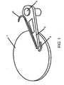
- Fig. 1 shows a rough sketch of an example of the optical storing/reading apparatus according to the embodiment 1 of the present invention.
- a slider 2 On a disc 1 (medium) revolving at high speed, a slider 2 , which is kept in a certain distance from the disc 1 by a buoyant force given by the hydrodynamic motion generated by the revolution and a loading force given by the arm 3 , is provided.
- the slider 2 is held at the distal end portion of the arm 3 , and can scan at desired position on the disc 1 by moving horizontally the arm 3 about a rotation axis 4 coupled with a motor.
- the light propagated an optical waveguide 5 on the arm 3 passes through an optical waveguide in the slider 2 , is converted into a near-field light by a minute aperture formed in a surface facing a disc of the slider 2, and is irradiated on the disc 1 .
- Scattering light generated by the interaction between this near-field light and a minute area on the surface of the disc 1 is converted into an electric signal by a light sensing device disposed within or near the slider 2, and supplied to a signal processing circuit, where the information of the minute area is readed.
- Fig. 2 shows a structure of the optical head according to the embodiment 1 of the present invention.
- the optical head 100 of this structure is composed of: a slider 6 having a minute aperture 8 and an in-slider optical waveguide 7 is formed therein; a holding member 14 for holding the slider 6; an in-arm optical waveguide 11 including a weighting member 12 for applying a loading force to the slider 6; and an arm 10, in which the in-arm optical waveguide 11 is formed.
- the slider 6 is disposed close to the distal end of the arm 10 and under the arm 10.
- the in-arm optical waveguide 11 is formed on top of the arm 10 in Fig. 2 , it may be also formed in the arm 10 or under the arm 10 .
- the light to be irradiated on the medium propagates through the in-arm optical waveguide 11 formed on the arm 10, and is guided to above the slider 6 .
- a light reflector surface 13 for deflecting the direction of light propagation is formed at a portion of the in-arm optical waveguide 11 , so that the light guided to above the slider 6 is deflected in its direction and is further guided to the in-slider optical waveguide 7 formed in the slider 6 .
- the light propagates through a protruded weighting member 12 , which is formed of a portion of the in-arm optical waveguide 11 and applying a loading force to the slider 6.
- the slider 6 which is connected with the arm 10 via the holding member 14 , there exists an inverse-cone shaped hole having a minute aperture 8 for detecting and generating a near-field light at the vertex of the conical shape of the hole, and the in-slider optical waveguide 7 is embedded within the hole.
- the light which has been introduced into the in-slider optical waveguide 7 via the weighting member 12 , is condensed around the minute aperture 8 , by the effect of a light reflecting surface 9 formed within the inverse-cone shaped hole with surrounding the in-slider optical waveguide 7 .
- the condensed light is converted into a near-field light by passing through the minute aperture 8 , and irradiated on a minute area formed on the medium.
- the slider 6 receives a buoyant force from the medium side, by the hydrodynamic motion of air generated by the high speed revolution of the medium.
- a loading force from the arm 10 having a suspension function to the slider 6 receiving the buoyant force, the distance between the medium and the minute aperture 8 for causing an interaction of near-field light can be kept in a constant level, and thereby recording and reading the accurate information can be performed based on the intensity distribution of the near-field light generated by the aperture.
- the slider 6 must be continually regulated in a proper posture in response to the undulation of medium surface, to keep its relative position constant, and it is an effective method to make the slider 6 adapt to the motion of medium by applying the loading force at one point on the center of gravity.
- the weighting member 12 for applying the loading force is formed of a portion of the in-arm optical waveguide 11 .
- the weighting member 12 is pressing the center of gravity of the slider 6 with the pointed vertex of the inverse-cone shaped protrusion, so that the slider 6 can be always regulated in a proper posture with respect to the motion of medium, and, at the same time, is also playing a role of guiding the light from the arm 10 side to the slider 6 side.
- the arm and the slider composing such a structure can be produced by the micro-machining process that is represented by that of silicon.
- the inverse-conical hole can be formed on a silicon substrate, which is the parent body of the slider, by an anisotropic etching method, and an optical minute aperture is formed at the vertex thereof.
- a laminated layer of an optical waveguide material for guiding the light to the aperture is produced, by laminating a high-reflectance material inside the hole.
- a material to be the optical waveguide is formed on a metal material, which have been formed so as to have a shape of the arm, and, by etching or by exposing and developing in a manner of photo-lithographic technique, a desired shape of the optical waveguide is produced.
- mass production is made easier, and thereby the miniaturization and mass production of the slider and the arm can be easily realized.
- the miniaturization and the lighter weight of the optical recording/reading apparatus can be realized.
- the optical head according to the embodiment 1 although it has a simple structure, it is possible that the posture of the slider is controlled freely according to the undulation of the disc surface, in response to the motion of medium revolving at a high speed, by forming the weighting member for applying a loading force to the slider with a portion of the optical waveguide, and that the distance between the disc and the slider is kept constant. At the same time, a stable and constant amount of light can be continually supplied from the minute aperture, by arranging the relative position between the in-armoptical waveguide and the in-slider optical waveguide to be constant.
- Fig. 3 shows a structure of the optical head according to the embodiment 2 of the present invention.
- the optical head 200 of this structure is composed of: a slider 6 having a minute aperture 8 and an in-slider optical waveguide 7 , which is provided with a weight-receiving member 15 at a portion, is formed therein; a holding member 14 for holding the slider 6 ; an in-arm optical waveguide 11 for applying a loading force to the slider 6; and an arm 10, in which the in-arm optical waveguide 11 is formed.
- the rough structure is similar to the embodiment 1, it is characterized in that a projection for receiving the loading force fromthe in-arm optical waveguide 11 is formed on the in-slider optical waveguide 7.
- the in-arm optical waveguide 11 may be formed anywhere of the arm 10 , i.e., on top of, in or under the arm 10 , similarly to Fig. 2 .
- the weight-receiving member 15 formed of a portion of the in-slider optical waveguide 7 is shaped conical, and contacts the in-arm optical waveguide 11 at the vertex of the cone.
- the light which has been reflected by the light reflector surface 13 and is to be transmitted toward the slider 6 , comes incident on the weight-receiving member 15 formed of a portion of the in-slider optical waveguide 7 , with keeping stability, and is guided to the minute aperture 8 .
- the embodiment 1 by adjusting the incident angle to the weight-receiving member 15 and its refractive index, the light incident on the in-slider optical waveguide 7 can be condensed to the minute aperture 8 .
- the vertex of projection of the weight-receiving member 15 is positioned above the gravity center of the slider 6 , and the posture of the slider 6 can be freely controlled on its posture correspondingly to the motion of the medium revolving at high speed, and thereby the distance between the medium and the slider 6 can be kept constant. According to such a configuration, the recording and reading with stable signals can be performed with high reliability.
- Fig. 4 shows a structure of the optical head according to the embodiment 3 of the present invention.
- the optical head 300 of this structure is similar to the embodiment 1 , it is characterized in that a portion of the in-arm optical waveguide 11 is shaped hemispherical, the portion being a weighting member 16 .
- a portion of the in-arm optical waveguide 11 is shaped hemispherical, the portion being a weighting member 16 .
- the in-arm optical waveguide 11 may be formed anywhere of the arm 10 , i.e., on top of, in or under the arm 10 .
- the spherical shape formed of a portion of the optical waveguide may be formed on the in-slider optical waveguide 7 instead, though not shown in figure. Also in this case, it has the same effect and an apparatus having high reliability can be produced.
- Fig. 5 shows a structure of the optical head according to the embodiment 4 of the present invention.
- a protrusion or a partial sphere is formed either on the in-slider optical waveguide or on the in-arm optical waveguide
- the optical head 400 shown in the embodiment 4 there exist those members provided on both sides, such as a weighting member 17 formed on the in-arm optical waveguide 11 and a weight-receiving member 18 formed on the in-slider optical waveguide 7 , respectively, and those members are contacting each other.
- those members are shown as hemispheres in Fig. 5 , they may be replaced by protrusions, of course.
- the in-arm optical waveguide 11 may be formed anywhere of the arm 10, i.e., on top of, in or under the arm 10, similarly to the above.
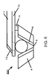
- Fig. 6 shows a structure of the optical head according to the embodiment 5 of the present invention.
- an inverse-conical hole is formed on a silicon substrate, which is the parent body of the slider 6 , so that a minute aperture 8 comes to the vertex of the conical hole.
- a function of condensing light on the minute aperture 8 is provided by forming a light-reflecting layer 9 inside the hole.
- a spherical lens 19 is inserted, and a loading force, which is given by the in-arm optical waveguide 11 , is applied to the slider 6 .
- the spherical lens 19 contacts with the inner wall of the hole in the slider and the in-arm optical waveguide, respectively, it can revolve freely and thereby enables the slider 6 to vary its posture with following the motion of the medium, and, with the flying-head technology, the slider 6 can be always kept in a certain relative position with respect to the medium.
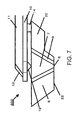
- Fig. 7 shows a structure of the optical head according to the embodiment 6 of the present invention.
- the optical head 600 of this structure is similar to the optical head 100 of the embodiment 1 shown in Fig. 2 , except that the slider 6 has a surface opposing to the medium (surface 22 facing the medium), which is recessed partly with leaving a protruded portion 20 from the side of the slider 6 .
- the thickness of the slider 6 at the position where the slider 6 is connected with the arm 10 via the holding member 14 is thinner than that of the slider 6 at the position where the loading force is applied via the weighting member 12 .
- the weighting member 12 is applying a loading force at the point pushing the gravity center of the slider 6 , so that the slider 6 can always keep a certain relative position according to the undulation of medium.
- the light which has propagated through the in-arm optical waveguide 11 and was reflected by the light reflector surface 13, propagates to the minute aperture 8 through the weighting member 12 .
- the position of the minute aperture 8 is determined to be a point nearly close to the gravity center in the surface 22 facing the medium.
- the gravity center of the slider 6 shifts by cutting a part of the surface 22 facing the medium of the slider 6 , and thereby the minute aperture 8 comes closer to the edge of the surface adjacent to the medium (surface 22 facing the medium).
- the minute aperture 8 can be disposed at desired position on the surface opposing to the medium (surface 22 facing the medium).
- the ratio of the thickness of the protruded portion 20 to that of the slider 6 at the minute aperture must be 9/10 or less, so that the slider 6 does not have an influence on the air flow when the slider 6 is floating above the medium, or that the aperture can be brought close to the medium, with preventing a part of the protruded portion 20 from hitting the medium.
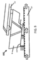
- Fig. 8 shows a positional relationship of the slider 6 with respect to the medium 21 , when the optical head 600 according to the embodiment 6 of the present invention is scanned over the medium 21 revolving at high speed.
- the slider 6 receives a buoyant force by the hydrodynamic motion of air when the medium 21 revolves at high speed, it is possible to keep the distance from the surface of the medium 21 constant, by applying a loading force from the arm 10 to the slider 6 .
- the posture of the slider 6 under such a situation is shown in Fig. 8 .
- the medium 21 runs in a direction shown by outlined arrows in Fig. 8
- air flow is generated between the medium 21 and the slider 6 in the direction shown by solid arrows in Fig. 8.
- the surface 22 facing the medium receives a strong pressure toward the direction perpendicular to the medium, and the gap from the medium 21 is expanded. It causes the slider 6 itself to incline, and, at the exit of the air flow, the distance between the surface 22 facing the medium of the slider 6 and the medium 21 becomes the minimum. Since the minute aperture 8 is formed at the area, where the distance from the medium 21 is small, in the surface 22 facing the medium of the slider 6 , the minute aperture 8 comes closer to the medium 21 , and SN ratio of the signal is improved and a high density read of information becomes possible.
- the minute aperture 8 is disposed within a range 0.4 mm or less from the edge of the surface 22 facing the medium of the slider 6 .
- the gravity center of the slider 6 is shifted, and thereby, the minute aperture 8 , which is disposed closer to the edge of the surface 22 facing the medium, comes to a point that is closer to the medium 21 when the medium revolves at high speed. It results an improvement of SN ratio, and an information recording apparatus further improved in high density, large capacity and small size can be realized.
- Fig. 9 shows another example of the optical head 700 according to the embodiment 6 of the present invention.
- Fig. 9 is showing an optical head 700 , in which the large part of the slider 6 is cut off to shift the gravity center of the slider 6 .
- the slider 6 may be configured so as to dispose the minute aperture 8 at the edge of the surface opposite to the medium (surface 22 facing the medium), by cutting off the large part of the surface, as shown in Fig. 7 , it may be also configured so as to dispose the minute aperture 8 at the end of the surface 22 facing the medium, by forming a large recess 23 in the surface opposite to the surface 22 facing the medium of the slider 6 to shift the gravity center of the slider 6 , as shown in Fig. 9 .
- the recess 23 by forming the recess 23 at the region that does not have an influence on the air flow during the high speed revolution, a stable floating height from the medium can be ensured, and thereby an optical recording apparatus having high SN ratio and excellent reliability can be produced.
- the position of the minute aperture in order to bring the minute aperture 8 sufficiently close to the medium, the position of the minute aperture must be shifted from the center toward the end by at least 1/10 of the length of the surface 22 facing the medium. Accordingly, the dimensions of the recess 23 should be selected to be 1/5 or more of the volume of the slider 6.
- Fig. 10 shows a structure of the optical head 800 according to the embodiment 7 of the present invention.
- This optical head 800 has a structure similar to the optical head 600 of the embodiment 6 shown in Fig. 7 , except that a protruded portion 24 is formed of a material different from that composing the slider 6.
- the protruded portion 24 may be formed of metal or epoxy group material. Since the density of different material will be different, the minute aperture 8 , which is positioned close to the gravity center of the slider 6 , comes to the edge in the surface 22 facing the medium, and thereby the distance from the medium can be made closer. Accordingly, the effect similar to that of the embodiment 6 can be obtained.
- the different material is not necessarily protruded, but it may be formed at a portion within the slider 6 as shown in Fig. 11.
- the minute aperture 8 which is positioned close to the gravity center, comes away from the center of the surface 22 facing the medium, and thereby the minute aperture 8 can be disposed in an area, where the distance from the medium is shorter.
- the main material of the slider 6 is Si
- this different material 25 may be copper, SUS, gold or the like, the density thereof is higher than that of Si. Contrary to that, even if an epoxy material, which has a density lower than that of Si, is used, the position of the minute aperture 8 can be shifted because of deviation of the gravity center.
- the structure of the optical head has been described to be the optical head 100 according to the embodiment 1 shown in Fig. 2 as an example, it should not be limited to the optical head 100, but the structure may be any of the optical head 200 shown with the embodiment 2 , the optical head 300 shown with the embodiment 3 , the optical head 400 shown with the embodiment 4 , and the optical head 500 shown with the embodiment 5 .
- the structure is formed so that the slider can move freely in correspondence with the medium revolving at high speed to keep the distance between the medium and the slider always constant, and the intensity of the near-field light, which is generated by the minute aperture formed in the slider, is stabilized to be uniform. Accordingly, stable recording and reading of the information signals with using light can be realized, without the influence by the intensity distribution of the near-field light. Moreover, since a light condensing function is provided in the optical waveguide, a recording/reading method giving a high SN ratio and being excellent in reliability becomes possible.
- the almost all components of the optical head according to the embodiment can be produced by micro-machining process with using Si or the like, the miniaturization of the entire apparatus can be achieved, and, at the same time, the cost reduction by the applicability of mass production can be realized.
- the aperture can be disposed at an area, which is closer to the medium, within the surface facing the medium, without obstructing the free motion of the slider, SN ratio of signals is improved and thereby the stability and reliability of products can be improved. Moreover, by utilizing of a smaller aperture, reading from and writing to more minute areas can be carried out, and thereby the improvement in resolution and in high density information becomes possible. Furthermore, since, even if the power of light source is reduced, reading at a sufficiently high speed is possible, the miniaturization, thinned configuration and cost reduction of products can be achieved.
Landscapes
- Physics & Mathematics (AREA)
- Optics & Photonics (AREA)
- Optical Head (AREA)
Abstract
Description
Claims (13)
- An optical head for recording and reading information, composed of:characterized in thata slider that receives a buoyant force generated by a relative motion with respect to a medium;a minute structure formed in a surface facing the medium of the slider, for generating a near-field light, detecting a near-field light or carrying out both of those;an in-slider optical waveguide mechanism formed in the slider and connected optically with the minute structure;an arm for holding the slider and applying a loading force to the slider;an in-arm optical waveguide mechanism formed on the arm, for guiding a light to the in-slider optical waveguide mechanism; andan optical waveguide mechanism contacting the in-arm optical waveguide mechanism and contacting the in-slider optical waveguide mechanism
the loading force is applied to the slider through the optical waveguide mechanism. - An optical head of claim 1 characterized in that the optical waveguide mechanism and the in-arm optical waveguide mechanism are formed in one united body.
- An optical head of claim 1 characterized in that the optical waveguide mechanism and the in-slider optical waveguide mechanism are formed in one united body.
- An optical head any of claims 1 through 3 characterized in that an area the optical waveguide mechanism contacts the in-arm optical waveguide mechanism, an area the optical waveguide mechanism contacts the in-slider optical waveguide mechanism, or areas of both of those are extremely small.
- An optical head any of claims 1 through 4 characterized in that the optical waveguide mechanism contacts the in-arm optical waveguide mechanism, the in-slider optical waveguide mechanism, or both of those at one point.
- An optical head any of claims 1 through 5 characterized in that a portion of the optical waveguide mechanism is shaped a cone or a hanging bell having a pointed top, and contacts at a top thereof.
- An optical head any of claims 1 through 6 characterized in that a portion of the optical waveguide mechanism is shaped a part of a spherical surface, and contacts at a part of the spherical surface.
- An optical head any of claims 1 through 7 characterized in that a portion of the optical waveguide mechanism has a light condensing function.
- An optical head any of claims 1 through 8 characterized in that the loading force is applied toward a center of gravity of the slider, the minute structure existing in the surface facing the medium is disposed on a straight line, which links a point the slider receives the loading force with the center of gravity of the slider.
- An optical head of claim 9 characterized in that a shape, a density or a combination thereof of the slider is determined so that the minute structure is disposed closed to an edge of the surface facing the medium.
- An optical head of claim 10 characterized in that there exists a recess having a size corresponding to 1/5 or more of a volume of the slider, at a portion in a surface opposite to the surface facing the medium of the slider.
- An optical head of claim 10 characterized in that there exists a difference in thickness having a differential level corresponding to 1/10 or more of an averaged thickness of the slider in a surface facing the medium of the slider.
- An optical head of claim 10 characterized in that a material having a density different from that of the slider occupies 1/10 or more of a total volume of the slider.
Applications Claiming Priority (5)
| Application Number | Priority Date | Filing Date | Title |
|---|---|---|---|
| JP24291699 | 1999-08-30 | ||
| JP24291699 | 1999-08-30 | ||
| JP2000127325 | 2000-04-27 | ||
| JP2000127325A JP4485012B2 (en) | 1999-08-30 | 2000-04-27 | Optical head |
| PCT/JP2000/005668 WO2001016949A1 (en) | 1999-08-30 | 2000-08-23 | Optical head |
Publications (3)
| Publication Number | Publication Date |
|---|---|
| EP1126449A1 true EP1126449A1 (en) | 2001-08-22 |
| EP1126449A4 EP1126449A4 (en) | 2005-02-02 |
| EP1126449B1 EP1126449B1 (en) | 2005-10-12 |
Family
ID=26535980
Family Applications (1)
| Application Number | Title | Priority Date | Filing Date |
|---|---|---|---|
| EP00954953A Expired - Lifetime EP1126449B1 (en) | 1999-08-30 | 2000-08-23 | Optical head |
Country Status (5)
| Country | Link |
|---|---|
| US (1) | US6567373B1 (en) |
| EP (1) | EP1126449B1 (en) |
| JP (1) | JP4485012B2 (en) |
| DE (1) | DE60023101T2 (en) |
| WO (1) | WO2001016949A1 (en) |
Cited By (2)
| Publication number | Priority date | Publication date | Assignee | Title |
|---|---|---|---|---|
| WO2003034416A3 (en) * | 2001-10-18 | 2003-06-19 | Koninkl Philips Electronics Nv | Slider for an optical data writing/reading apparatus, and apparatus comprising such a slider |
| EP1610318A4 (en) * | 2003-03-28 | 2007-11-28 | Fujitsu Ltd | HEAD EMITTING LIGHT AND INFORMATION STORAGE DEVICE |
Families Citing this family (12)
| Publication number | Priority date | Publication date | Assignee | Title |
|---|---|---|---|---|
| DE69936475T2 (en) * | 1998-11-09 | 2008-03-06 | Seiko Instruments Inc. | Near field scanning head and manufacturing method therefor |
| US7069569B2 (en) * | 2000-02-01 | 2006-06-27 | Research Investment Network, Inc. | Near-field optical head system with integrated slider and laser |
| JP4482254B2 (en) * | 2001-09-27 | 2010-06-16 | セイコーインスツル株式会社 | Optical head |
| JP4325172B2 (en) * | 2002-11-01 | 2009-09-02 | 株式会社日立製作所 | Near-field light generating probe and near-field light generating apparatus |
| JP4482485B2 (en) * | 2005-05-18 | 2010-06-16 | セイコーインスツル株式会社 | Head module |
| US7272041B2 (en) * | 2005-06-30 | 2007-09-18 | Intel Corporation | Memory array with pseudo single bit memory cell and method |
| JP4565452B2 (en) * | 2006-07-27 | 2010-10-20 | セイコーインスツル株式会社 | Head gimbal mechanism and information recording / reproducing apparatus |
| US8169743B2 (en) * | 2007-07-20 | 2012-05-01 | Hitachi Global Storage Technologies, Netherlands B.V. | Minimizing slider vibration effects on a magnetic transducer |
| JP2009093774A (en) * | 2007-10-12 | 2009-04-30 | Fujitsu Ltd | Head slider |
| US8325566B2 (en) * | 2009-03-19 | 2012-12-04 | Tdk Corporation | Thermally-assisted magnetic recording head having a light source at least inclined from an opposed-to-medium surface |
| US8194509B2 (en) * | 2009-07-30 | 2012-06-05 | Tdk Corporation | Thermally-assisted magnetic recording head comprising light source with photonic-band layer |
| US8654617B2 (en) | 2012-03-21 | 2014-02-18 | Tdk Corporation | Thermally-assisted magnetic recording head with optically isolating waveguide, head gimbal assembly, head arm assembly, magnetic disk unit, and light transmission unit |
Family Cites Families (16)
| Publication number | Priority date | Publication date | Assignee | Title |
|---|---|---|---|---|
| JPH0573980A (en) * | 1991-09-12 | 1993-03-26 | Ricoh Co Ltd | Optical head for optical disk drive device |
| US5351229A (en) * | 1991-12-24 | 1994-09-27 | International Business Machines Corporation | Tribo-attractive contact slider for an optical read/write system |
| JPH05342789A (en) * | 1992-06-10 | 1993-12-24 | Sony Corp | Levitation type magnetic head device |
| JPH0845041A (en) * | 1994-07-29 | 1996-02-16 | Sony Corp | Flying magnetic head |
| KR100230242B1 (en) * | 1994-12-26 | 1999-11-15 | 윤종용 | High density optical recording method and device |
| EP0966738A1 (en) * | 1996-04-15 | 1999-12-29 | Digital Papyrus Technologies | A flying head positioner with fine positioning |
| US5850375A (en) * | 1996-07-30 | 1998-12-15 | Seagate Technology, Inc. | System and method using optical fibers in a data storage and retrieval system |
| JP2950266B2 (en) * | 1996-12-20 | 1999-09-20 | 日本電気株式会社 | Contact type magnetic head slider |
| KR100422434B1 (en) * | 1997-04-08 | 2004-03-12 | 시게이트 테크놀로지 엘엘씨 | Improved suspension design for a head gimbal assembly |
| JPH11273124A (en) * | 1998-03-17 | 1999-10-08 | Asahi Optical Co Ltd | Optical disk drive |
| JP4109744B2 (en) * | 1998-03-24 | 2008-07-02 | セイコーインスツル株式会社 | Near-field optical head |
| JP3895471B2 (en) * | 1998-07-17 | 2007-03-22 | 富士通株式会社 | Lens actuator |
| DE69936475T2 (en) * | 1998-11-09 | 2008-03-06 | Seiko Instruments Inc. | Near field scanning head and manufacturing method therefor |
| JP3400374B2 (en) * | 1999-01-27 | 2003-04-28 | 日本電信電話株式会社 | Optical pickup |
| JP2001028139A (en) * | 1999-07-14 | 2001-01-30 | Tdk Corp | Optical probe, method of manufacturing the same, and optical head |
| JP4421742B2 (en) * | 1999-07-26 | 2010-02-24 | セイコーインスツル株式会社 | Optical head |
-
2000
- 2000-04-27 JP JP2000127325A patent/JP4485012B2/en not_active Expired - Fee Related
- 2000-08-23 US US09/807,771 patent/US6567373B1/en not_active Expired - Lifetime
- 2000-08-23 WO PCT/JP2000/005668 patent/WO2001016949A1/en not_active Ceased
- 2000-08-23 EP EP00954953A patent/EP1126449B1/en not_active Expired - Lifetime
- 2000-08-23 DE DE60023101T patent/DE60023101T2/en not_active Expired - Lifetime
Cited By (3)
| Publication number | Priority date | Publication date | Assignee | Title |
|---|---|---|---|---|
| WO2003034416A3 (en) * | 2001-10-18 | 2003-06-19 | Koninkl Philips Electronics Nv | Slider for an optical data writing/reading apparatus, and apparatus comprising such a slider |
| CN1322501C (en) * | 2001-10-18 | 2007-06-20 | 皇家飞利浦电子股份有限公司 | Slider for an optical data writing/reading apparatus, and apparatus comprising such a slider |
| EP1610318A4 (en) * | 2003-03-28 | 2007-11-28 | Fujitsu Ltd | HEAD EMITTING LIGHT AND INFORMATION STORAGE DEVICE |
Also Published As
| Publication number | Publication date |
|---|---|
| EP1126449A4 (en) | 2005-02-02 |
| WO2001016949A1 (en) | 2001-03-08 |
| EP1126449B1 (en) | 2005-10-12 |
| US6567373B1 (en) | 2003-05-20 |
| DE60023101D1 (en) | 2006-02-23 |
| JP2001143316A (en) | 2001-05-25 |
| JP4485012B2 (en) | 2010-06-16 |
| DE60023101T2 (en) | 2006-05-11 |
Similar Documents
| Publication | Publication Date | Title |
|---|---|---|
| JP4094229B2 (en) | Near-field optical head and manufacturing method thereof | |
| EP1126449B1 (en) | Optical head | |
| US6785201B2 (en) | Optical information recording and reading apparatus | |
| US7034277B2 (en) | Near-field light-generating element for producing localized near-field light, near-field optical recording device, and near-field optical microscope | |
| EP1120778B1 (en) | Optical head | |
| WO1998052193A1 (en) | Optical disc data storage system using optical waveguide | |
| JP2002245659A (en) | Information recording / reproducing device | |
| US6376827B1 (en) | Near field optical memory head | |
| EP0996122B1 (en) | Near-field optical head | |
| EP0986058B1 (en) | Near-field optical head | |
| JP4610855B2 (en) | Near-field light generating element, near-field light recording device, and near-field light microscope | |
| JPH11144274A (en) | Galvanometer mirror deflection angle detector | |
| JPH11144273A (en) | Galvanometer mirror deflection angle detector | |
| KR100644600B1 (en) | Optical head for near field recording and playback | |
| JP4593666B2 (en) | Near-field light generating element, near-field light recording device, and near-field light microscope | |
| JP4482254B2 (en) | Optical head | |
| JPH11134684A (en) | Optical information recording / reproducing head | |
| JPH11149660A (en) | Optical information recording / reproducing head | |
| JPH11259888A (en) | Deflection device and optical information recording / reproducing head | |
| JPH11134681A (en) | Optical information recording / reproducing head | |
| JP2003022559A (en) | Near-field optical head | |
| JPH11144278A (en) | Optical information recording / reproducing head | |
| JPH11142774A (en) | Galvano mirror | |
| JPH11134685A (en) | Optical information recording / reproducing head | |
| JPH11134682A (en) | Optical information recording / reproducing head |
Legal Events
| Date | Code | Title | Description |
|---|---|---|---|
| PUAI | Public reference made under article 153(3) epc to a published international application that has entered the european phase |
Free format text: ORIGINAL CODE: 0009012 |
|
| AK | Designated contracting states |
Kind code of ref document: A1 Designated state(s): AT BE CH CY DE DK ES FI FR GB GR IE IT LI LU MC NL PT SE |
|
| AX | Request for extension of the european patent |
Free format text: AL;LT;LV;MK;RO;SI |
|
| 17P | Request for examination filed |
Effective date: 20010813 |
|
| RBV | Designated contracting states (corrected) |
Designated state(s): DE FR GB |
|
| A4 | Supplementary search report drawn up and despatched |
Effective date: 20041216 |
|
| RIC1 | Information provided on ipc code assigned before grant |
Ipc: 7G 11B 7/12 A Ipc: 7G 11B 7/125 B |
|
| GRAP | Despatch of communication of intention to grant a patent |
Free format text: ORIGINAL CODE: EPIDOSNIGR1 |
|
| GRAS | Grant fee paid |
Free format text: ORIGINAL CODE: EPIDOSNIGR3 |
|
| GRAA | (expected) grant |
Free format text: ORIGINAL CODE: 0009210 |
|
| AK | Designated contracting states |
Kind code of ref document: B1 Designated state(s): DE FR GB |
|
| REG | Reference to a national code |
Ref country code: GB Ref legal event code: FG4D |
|
| REF | Corresponds to: |
Ref document number: 60023101 Country of ref document: DE Date of ref document: 20060223 Kind code of ref document: P |
|
| ET | Fr: translation filed | ||
| PLBE | No opposition filed within time limit |
Free format text: ORIGINAL CODE: 0009261 |
|
| STAA | Information on the status of an ep patent application or granted ep patent |
Free format text: STATUS: NO OPPOSITION FILED WITHIN TIME LIMIT |
|
| 26N | No opposition filed |
Effective date: 20060713 |
|
| REG | Reference to a national code |
Ref country code: FR Ref legal event code: PLFP Year of fee payment: 17 |
|
| REG | Reference to a national code |
Ref country code: FR Ref legal event code: PLFP Year of fee payment: 18 |
|
| REG | Reference to a national code |
Ref country code: FR Ref legal event code: PLFP Year of fee payment: 19 |
|
| PGFP | Annual fee paid to national office [announced via postgrant information from national office to epo] |
Ref country code: DE Payment date: 20180807 Year of fee payment: 19 Ref country code: FR Payment date: 20180712 Year of fee payment: 19 |
|
| PGFP | Annual fee paid to national office [announced via postgrant information from national office to epo] |
Ref country code: GB Payment date: 20180822 Year of fee payment: 19 |
|
| REG | Reference to a national code |
Ref country code: DE Ref legal event code: R119 Ref document number: 60023101 Country of ref document: DE |
|
| GBPC | Gb: european patent ceased through non-payment of renewal fee |
Effective date: 20190823 |
|
| PG25 | Lapsed in a contracting state [announced via postgrant information from national office to epo] |
Ref country code: FR Free format text: LAPSE BECAUSE OF NON-PAYMENT OF DUE FEES Effective date: 20190831 Ref country code: DE Free format text: LAPSE BECAUSE OF NON-PAYMENT OF DUE FEES Effective date: 20200303 |
|
| PG25 | Lapsed in a contracting state [announced via postgrant information from national office to epo] |
Ref country code: GB Free format text: LAPSE BECAUSE OF NON-PAYMENT OF DUE FEES Effective date: 20190823 |