EP1120778B1 - Optical head - Google Patents
Optical head Download PDFInfo
- Publication number
- EP1120778B1 EP1120778B1 EP00946388A EP00946388A EP1120778B1 EP 1120778 B1 EP1120778 B1 EP 1120778B1 EP 00946388 A EP00946388 A EP 00946388A EP 00946388 A EP00946388 A EP 00946388A EP 1120778 B1 EP1120778 B1 EP 1120778B1
- Authority
- EP
- European Patent Office
- Prior art keywords
- slider
- light
- record medium
- optical head
- arm
- Prior art date
- Legal status (The legal status is an assumption and is not a legal conclusion. Google has not performed a legal analysis and makes no representation as to the accuracy of the status listed.)
- Expired - Lifetime
Links
Images


Classifications
-
- B—PERFORMING OPERATIONS; TRANSPORTING
- B82—NANOTECHNOLOGY
- B82Y—SPECIFIC USES OR APPLICATIONS OF NANOSTRUCTURES; MEASUREMENT OR ANALYSIS OF NANOSTRUCTURES; MANUFACTURE OR TREATMENT OF NANOSTRUCTURES
- B82Y15/00—Nanotechnology for interacting, sensing or actuating, e.g. quantum dots as markers in protein assays or molecular motors
-
- G—PHYSICS
- G11—INFORMATION STORAGE
- G11B—INFORMATION STORAGE BASED ON RELATIVE MOVEMENT BETWEEN RECORD CARRIER AND TRANSDUCER
- G11B7/00—Recording or reproducing by optical means, e.g. recording using a thermal beam of optical radiation by modifying optical properties or the physical structure, reproducing using an optical beam at lower power by sensing optical properties; Record carriers therefor
- G11B7/12—Heads, e.g. forming of the optical beam spot or modulation of the optical beam
- G11B7/122—Flying-type heads, e.g. analogous to Winchester type in magnetic recording
-
- B—PERFORMING OPERATIONS; TRANSPORTING
- B82—NANOTECHNOLOGY
- B82Y—SPECIFIC USES OR APPLICATIONS OF NANOSTRUCTURES; MEASUREMENT OR ANALYSIS OF NANOSTRUCTURES; MANUFACTURE OR TREATMENT OF NANOSTRUCTURES
- B82Y10/00—Nanotechnology for information processing, storage or transmission, e.g. quantum computing or single electron logic
-
- G—PHYSICS
- G11—INFORMATION STORAGE
- G11B—INFORMATION STORAGE BASED ON RELATIVE MOVEMENT BETWEEN RECORD CARRIER AND TRANSDUCER
- G11B7/00—Recording or reproducing by optical means, e.g. recording using a thermal beam of optical radiation by modifying optical properties or the physical structure, reproducing using an optical beam at lower power by sensing optical properties; Record carriers therefor
- G11B7/12—Heads, e.g. forming of the optical beam spot or modulation of the optical beam
- G11B7/135—Means for guiding the beam from the source to the record carrier or from the record carrier to the detector
- G11B7/1384—Fibre optics
-
- G—PHYSICS
- G11—INFORMATION STORAGE
- G11B—INFORMATION STORAGE BASED ON RELATIVE MOVEMENT BETWEEN RECORD CARRIER AND TRANSDUCER
- G11B7/00—Recording or reproducing by optical means, e.g. recording using a thermal beam of optical radiation by modifying optical properties or the physical structure, reproducing using an optical beam at lower power by sensing optical properties; Record carriers therefor
- G11B7/12—Heads, e.g. forming of the optical beam spot or modulation of the optical beam
- G11B7/135—Means for guiding the beam from the source to the record carrier or from the record carrier to the detector
- G11B7/1387—Means for guiding the beam from the source to the record carrier or from the record carrier to the detector using the near-field effect
-
- G—PHYSICS
- G11—INFORMATION STORAGE
- G11B—INFORMATION STORAGE BASED ON RELATIVE MOVEMENT BETWEEN RECORD CARRIER AND TRANSDUCER
- G11B7/00—Recording or reproducing by optical means, e.g. recording using a thermal beam of optical radiation by modifying optical properties or the physical structure, reproducing using an optical beam at lower power by sensing optical properties; Record carriers therefor
- G11B7/12—Heads, e.g. forming of the optical beam spot or modulation of the optical beam
- G11B7/135—Means for guiding the beam from the source to the record carrier or from the record carrier to the detector
- G11B7/1372—Lenses
- G11B2007/13727—Compound lenses, i.e. two or more lenses co-operating to perform a function, e.g. compound objective lens including a solid immersion lens, positive and negative lenses either bonded together or with adjustable spacing
Definitions
- the present invention relates to an optical head for a recording apparatus for recording and reproducing information at a high density by detecting an interaction between light and a very small area of a surface of a record medium by utilizing light, particularly for a near-field light utilizing information recording apparatus for observing structural information or optical information at a very small area equal to or smaller than a wavelength of incident light for utilizing in information recording and reproduction at a high density.
- a high resolution probe utilizing near-field light is used in a near-field optical microscope or a near-field optical head.
- a near-field optical microscope or a near-field optical head By generating near-field light from a front end of a probe and detecting propagated light generated as a result of an interaction between near-field light and a sample of a microscope or a record medium, there is provided a spacial resolution exceeding the diffraction limit of light.
- a near-field light microscope achieves a resolution exceeding the diffraction limit of a conventional optical microscope by this principle. Further, when such a near-field optical probe is utilized in a near-field optical head, there can be achieved a data recording density exceeding that of a conventional optical disk.
- the basic constitution is the same as that of a conventional magnetic disk apparatus and a near-field light probe is used in place of a magnetic head.
- the near-field light probe can always maintain a constant posture in operation relative to a surface of record medium by a flexible structure.
- a typical f lexible structure is referred to as flexure structure and a slider is connected to a frame-like structure only in x-axis direction on an inner side of the frame-like structure connected to the suspension arm only in z-axis direction.
- the frame-like structure is provided with a rotational degree of freedom with respect to z-axis and the slider is provided with a degree of freedom with x-axis as a rotating axis relative to the frame-like structure. That is, the slider is provided with rotational degrees of freedom with z-axis and x-axis as axes thereof relative to the suspension arm.
- an optical fiber or a waveguide is connected to the slider or light is irradiated to an upper face or a side face of the slider.
- EP 0549237 discloses an optical recording system in which the optical head is operated in physical contact with the surface of the optical recording medium during system operation at a selected operating speed.
- the optical head includes one or more optical elements mounted on a substrate which is in physical, sliding contact with the recording medium.
- the substrate is fabricated from a crystalline material which has a nonlinear load versus friction characteristic in the negative load region.
- a restoring force is generated which maintains the optical head in physical contact with the recording medium overcoming any lifting forces generated by the moving air layer adjacent the recording medium surface. This allows the head to be operated with a negative external load applied.
- Utilizing the optical head having the objective lens mounted on the substrate in close proximity to the recording medium surface allows high density recording to be achieved without the requirement of an electro-mechanical servo system to provide beam focusing for the system.
- an optical head having the features set forth in claim 1.
- the slider and the suspension arm are connected with high and stabilised efficiency by light while maintaining the posture of the slider constant relative to the surface of the record medium.
- a stable output signal is provided and high-speed recording/reproduction can be carried out.
- downsizing of the entire apparatus is realised.
- the flexible structure comprises an optical waveguide.
- the flexible structure is fabricated from a single substrate and accordingly, fabrication steps can be simplified and the optical head can be fabricated at a low cost.
- the arm-to-slider light guiding structure is constituted by a structure having a small light propagation loss.
- the arm to slider light guiding structure is formed in a linear line or a shape having a small radius of curvature.
- the aperture is as small as a size equal to or smaller than a wavelength of light and the light interacting with the record medium is near-field light.
- Fig. 1 shows an outline of an optical data storage apparatus according to a first example, which does not form part of the invention.
- the basic constitution is similar to that of a magnetic disk apparatus of related art, a flexure 3 is formed at a front end portion of a suspension arm 2 in order to rotate at high speed a record medium 4 in a state in which a near-field light aperture (not illustrated) is made proximate to the surface of the record medium 4 up to several tens nanometers and float the near-field light aperture always at a constant arrangement relative to the record medium 4.
- the suspension arm 2 is movable in the radius direction of the record medium 4 by a voice coil motor 5. Light is guided to a vicinity of the flexure 3 by an optical waveguide or an optical fiber adhered or formed on the suspension arm 2.
- Scattered light generated as a result of an interaction by the near-field with the record medium is received by, for example, a light receiving element (not illustrated) adhered onto the flexure, converted into an electric signal and transmitted to a signal processing circuit (not illustrated).
- the signal is amplified by an amplifying circuit as necessary to thereby constitute a reproduced signal of information.
- an illumination mode for generating the near-field light from a very small aperture and scattering thereof by the record medium there is carried out an illumination mode for generating the near-field light from a very small aperture and scattering thereof by the record medium
- the present invention can similarly be embodied also by a collection mode for generating the near-field light at a surface of the record medium and focusing light scattered by the very small aperture.
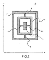
- Fig. 2 shows a flexure structure for a near-field light head according to Example 1.
- the slider is provided with degrees of freedom of rotating around z-axis and x-axis. There is realized a function of following out-of-face vibration of the record medium rotating at high speed.
- Fig. 3 shows an enlarged view of the flexure for the near-field light head according to Example 1.
- An optical waveguide 12 is adhered to a surface of a supporter for connecting the suspension arm and the slider.
- the optical waveguide 12 is a waveguide on a silicon substrate fabricated by a semiconductor process and is adhered onto the flexure.
- the light waveguide 12 is adhered thereto by making optical axes of a light incident port (not illustrated) of the slider and the optical waveguide 12 coincide with each other.
- the posture of the slider relative to the surface of the record medium can be maintained constant, further, since the waveguide is directly connected thereto, there is realized incidence of light to the slider at a constant efficiency. Since the interaction by the near-field light is utilized, there is realized recording/reproduction at a record density exceeding the diffraction limit of light.
- the near-field light generated from the very small aperture is attenuated strongly dependent upon a distance from the very small aperture, however, according to the embodiment, the slider follows the movement of the record medium by the flexure structure and accordingly, stable interaction is always produced and there is provided a signal output which is always stabilized during recording/reproduction of information. Further, small-sized formation of the entire apparatus can be realized since the flexure and the light guiding structure are integrated. Such a flexure is easy to fabricate and can be mass-produced at a low cost.
- Fig. 4 shows a total view of a suspension arm integrated with a flexure for a near-field light head according to Embodiment 1 of the invention.
- the total is constructed by a structure of one sheet of flat plate of a silicon substrate 21.
- a waveguide 19 is formed at an upper face of the silicon substrate 21 and is formed from a side (right end of the drawing) of a rotating shaft (not illustrated) of a suspension arm to a slider 18 in the flexure.
- the light guiding structure is not necessary that the light guiding structure is limited to the constitution with silicon for the substrate but there may be constructed a light guiding structure fabricated at inside of a supporter of plastic materials.
- Light propagated to the slider 18 is guided to the very small aperture by changing a propagating direction thereof by, for example, forming a light reflecting film at an upper face of the slider.
- the light is converted into near-field light by the very small aperture and interacts with the record medium.
- An operational mechanism thereafter is the same as that explained in Embodiment 1 and accordingly, an explanation thereof will be omitted.
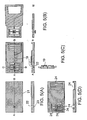
- Figs. 5A through 5D show a method of fabricating a suspension arm integrated with the flexure for a near-field light head according to Embodiment 1.
- top views are shown on the upper side and sectional views taken along a line segment AB indicated in the Fig. 5A are shown on the lower side.
- the silicon substrate 21 having a thickness of about 500 through 1000 micrometers, there may be used a substrate having other thickness.
- a taper structure 22 in a shape of an inverse cone at the silicon substrate 21 by anisotropic etching.
- a very small aperture 23 having a diameter of about 100 nanometers at a top portion of the inverse cone, that is, a bottom face of the silicon substrate.
- recesses 24 patterned at an upper face of the silicon substrate by etching. The portions finally constitute through holes.
- Fig. 5C after vapor-depositing a light shielding film (not illustrated) of aluminum at the taper portion 22 by a thickness of 100 nanometers, the optical waveguide 19 having a clad core clad structure is patterned and laminated.
- a light shielding film not illustrated
- FIG. 5C is the sectional view taken along the line segment AB in an upper view and a lower view is a sectional view taken along a line segment CD in the upper view.
- Fig. 5D the recesses 24 are removed from a lower face of the silicon substrate by etching to thereby finish the suspension arm.
- the suspension arm formed by such a method is constructed by a structure having a function of a flexure structure provided to a suspension arm for a magnetic disk apparatus of related art and integrated with all of a slider, near-field light head and a waveguide structure for guiding light from a light source (not illustrated) to the very small aperture at a front end of the head.
- Fig. 6 shows a total view of a suspension arm integrated with a flexure for a near-field light head according to Embodiment 2.
- a slider 34 carries out rolling operation by a rolling support shaft 33 and pitching operation is carried out by pitching support shafts 31.
- the slider 34 is formed with a taper at a front end of which a very small aperture 32 is formed.
- An optical waveguide 36 is formed at inside of the suspension arm as in Embodiment 1.
- the feature of the embodiment resides in that by arranging the pitching support shafts 31 to be directed to the length direction of the suspension arm, the slider 34 can be formed to linearly direct to the slider 34 without being curved at a midway thereof .
- the shafts are formed by a shape which is slender in the length direction of the suspension arm and accordingly, the shafts are difficult to deform in the rolling direction and are easy to deform in the pitching direction.
- the pitching support shafts 31 are formed in a shape in which three legs of beams are connected to the slider, any number of legs of beams may be connected thereto and there may be formed any shape so far as there is formed a structural member capable of pitching and having some linear shape from the suspension arm to the slider.
- optical waveguide 36 Since the optical waveguide 36 is formed linearly, propagation loss at a midway thereof can significantly be restrained. It is apparent from the embodiment that such an effect can be realized by any structure other than the structure of the embodiment in which some structural member is linearly connected from a suspension arm to a slider.
- a structure similar to that in the above-described embodiment can be fabricated and it is possible that scattered light is received by a light receiving element arranged at a vicinity of the very small projection and the light is thereafter propagated by an optical waveguide at inside of a suspension arm having the above-described structure and transmitted to a signal processing circuit. Thereby, light can be propagated with a stabilized efficiency.
- Fig. 7 shows a top view of a flexure 40 for a near-field light head according to a second example, which does not form part of the invention as claimed.
- the flexure 40 is adhered to a suspension arm, not illustrated, at an adhering portion 41.
- a movable portion 42 is not adhered to the suspension arm and accordingly, is provided with some degrees of freedom.
- a near-field light head 43 is adhered to a cantilever 45 formed at a front end of the flexure 40.
- the flexure 40 comprises Si and a waveguide 46 is fabricated by forming a silicon oxide filmon Si. Although in this case, the wave guide 46 is fabricated at an upper face of the flexure 40, the waveguide 46 can also be fabricated at a lower face thereof.
- Fig. 8 is a sectional view of the near-field light head 43 and a front end portion of the flexure 40 according to Example 2.
- the near-field light head 43 is formed with air bearing surfaces 51 at a lower face thereof (face directed to a record medium, not illustrated) and a very small aperture 53 surrounded by a light shielding film 52.
- the air bearing surfaces 51 receive air bearing force produced by rotational movement of the record medium from a lower direction of the drawing, thereby, the near-field light head 43 and the movable portion 42 of the flexure 40 are moved and the near-field light head 43 maintains always at the same posture relative to the surface of the record medium.
- Light is emitted from the waveguide 46, reflected by the mirror face 44 and is propagated to the very small aperture 53 with stabilized high efficiency.
- the waveguide 46 is formed at a position shifted from center of the flexure 40 to the right side of the drawing in order to make the very small aperture 53 as proximate to the record medium as possible.
- Fig. 9 it is possible to construct a structure in which the waveguide 46 is formed at the center of the flexure 40 and light is curved by the mirror face 44 on the cantilever 45. This is basically the same as the structure which is embodied in Embodiment 2.
- an optical head as defined in claim 1.
- the optical head according to the first aspect of the optical head wherein the flexible structure is fabricated by an optical waveguide. Therefore, there is achieved the effect that in addition to the effect realized by the first aspect of the optical head, the flexible structure is fabricated from a single substrate and accordingly, fabricating steps are simplified and the optical head can be fabricated at a low cost.
- the optical head according to the first aspect or the second aspect of the optical heads wherein the arm-to-slider light guiding structure is constituted by a structure having a small light propagation loss. Therefore, there is achieved the effect that in addition to the effect realized by the first aspect or the second aspect of the optical heads, light loss in guiding light between the arm and the slider can be minimized.
- the optical head according to the first aspect or the second aspect of the optical head wherein the arm-to-slider light guiding structure is formed in a linear line or a shape having a small radius of curvature. Therefore, there is achieved the effect that in addition to the effect realized by the first aspect or the second aspect of the optical heads, light loss in conducting light between the arm and the slider can be minimized.
- the optical head according to any one of the first aspect through the fourth aspect of the optical heads wherein the aperture is as small as a size equal to or smaller than a wavelength of light and the light interacting with the record medium is near-field light- Therefore, in addition to the effect realized by the first aspect through the fourth aspect of the optical heads, by utilizing ultra resolution which is a characteristic of the near-field light, a record density exceeding a diffraction limit of light is realized. Further, with regard to each of the effects realized by the first aspect through the fourth aspect of the optical heads, there is achieved the effect that regardless of distance dependency of optical intensity which is a characteristic of the near-field light, a stable signal output is provided and high speed recording/reproduction can be carried out.
Landscapes
- Engineering & Computer Science (AREA)
- Physics & Mathematics (AREA)
- Optics & Photonics (AREA)
- Nanotechnology (AREA)
- Chemical & Material Sciences (AREA)
- Crystallography & Structural Chemistry (AREA)
- Mathematical Physics (AREA)
- Theoretical Computer Science (AREA)
- Health & Medical Sciences (AREA)
- Life Sciences & Earth Sciences (AREA)
- General Health & Medical Sciences (AREA)
- Molecular Biology (AREA)
- Optical Head (AREA)
Abstract
Description
- The present invention relates to an optical head for a recording apparatus for recording and reproducing information at a high density by detecting an interaction between light and a very small area of a surface of a record medium by utilizing light, particularly for a near-field light utilizing information recording apparatus for observing structural information or optical information at a very small area equal to or smaller than a wavelength of incident light for utilizing in information recording and reproduction at a high density.
- In recent years, there has been intensely promoted development of an apparatus of recording and reproducing information at a high density utilizing light such as an optical disk. For high density formation of information, it is necessary to shorten a wavelength by utilizing ultraviolet ray or the like, however, there is a limit therein and therefore, there is a method of using an objective solid immersion lens. As other method of effectively shortening a wavelength, there is pointed out utilization of near-field light for constituting a component of a wave number by an imaginary number.
- A high resolution probe utilizing near-field light is used in a near-field optical microscope or a near-field optical head. By generating near-field light from a front end of a probe and detecting propagated light generated as a result of an interaction between near-field light and a sample of a microscope or a record medium, there is provided a spacial resolution exceeding the diffraction limit of light. There is also a method of detecting near-field light generated as a result of an interaction between incident propagated light and a sample or a record medium by a probe. A near-field light microscope achieves a resolution exceeding the diffraction limit of a conventional optical microscope by this principle. Further, when such a near-field optical probe is utilized in a near-field optical head, there can be achieved a data recording density exceeding that of a conventional optical disk.
- According to a data storage apparatus using a near-field light head, the basic constitution is the same as that of a conventional magnetic disk apparatus and a near-field light probe is used in place of a magnetic head. At this occasion, the near-field light probe can always maintain a constant posture in operation relative to a surface of record medium by a flexible structure. When a length direction of a suspension arm is defined as z-axis, a direction orthogonal to the z-axis and in parallel with the record medium and a vertical direction are def ined as x-axis and y-axis respectively, a typical f lexible structure is referred to as flexure structure and a slider is connected to a frame-like structure only in x-axis direction on an inner side of the frame-like structure connected to the suspension arm only in z-axis direction. By such a structure, the frame-like structure is provided with a rotational degree of freedom with respect to z-axis and the slider is provided with a degree of freedom with x-axis as a rotating axis relative to the frame-like structure. That is, the slider is provided with rotational degrees of freedom with z-axis and x-axis as axes thereof relative to the suspension arm.
- In making light incident on the slider relative to the suspension arm constituted in this way, an optical fiber or a waveguide is connected to the slider or light is irradiated to an upper face or a side face of the slider.
- However, when light is made incident on the slider by the above-described structure, connection of some member such as the waveguide to the slider, hinders free movement of the slider, it is difficult to maintain the posture of the slider and a distance between a surface of the record medium and a very small aperture cannot be maintained constant. When the distance between the surface of the record medium and the very small aperture is not constant, optical intensity related to the interaction is not made constant and a stable output signal cannot be provided. In order to carry out high-speed recording/reproduction, it is necessary to reduce noise, however, the reduction becomes difficult when the signal is not stabilized. Further, when light is made incident on the slider by aerial propagation, it is extremely difficult to move incident light in synchronism with the movement of the slider. When light is made incident on an upper face of the slider by the aerial propagation, it is necessary to arrange a structure member for light incidence at an upper space of the slider and there poses a problem that the entire apparatus becomes large-sized.
-
EP 0549237 discloses an optical recording system in which the optical head is operated in physical contact with the surface of the optical recording medium during system operation at a selected operating speed. The optical head includes one or more optical elements mounted on a substrate which is in physical, sliding contact with the recording medium. The substrate is fabricated from a crystalline material which has a nonlinear load versus friction characteristic in the negative load region. When the head is in sliding contact with the recording medium surface, a restoring force is generated which maintains the optical head in physical contact with the recording medium overcoming any lifting forces generated by the moving air layer adjacent the recording medium surface. This allows the head to be operated with a negative external load applied. Utilizing the optical head having the objective lens mounted on the substrate in close proximity to the recording medium surface allows high density recording to be achieved without the requirement of an electro-mechanical servo system to provide beam focusing for the system. - United States Patent No.
5,850,375 describes an optical head having the features set forth in the preamble ofclaim 1. - In order to resolve the above-described problems, according to a first aspect of the invention, there is provided an optical head having the features set forth in
claim 1. - According to the first aspect of the present invention, it is realised that when the slider scans the surface of the record medium, the slider and the suspension arm are connected with high and stabilised efficiency by light while maintaining the posture of the slider constant relative to the surface of the record medium. Thereby, a stable output signal is provided and high-speed recording/reproduction can be carried out. Further, in comparison with related art in which the flexible structure and the arm to slider light guiding structure are separate items, downsizing of the entire apparatus is realised.
- Preferably, the flexible structure comprises an optical waveguide.
- In addition to an effect realized by the first aspect of the optical head, the flexible structure is fabricated from a single substrate and accordingly, fabrication steps can be simplified and the optical head can be fabricated at a low cost.
- Preferably, the arm-to-slider light guiding structure is constituted by a structure having a small light propagation loss.
- In addition to an effect realized by the first aspect of the optical head, light loss in guiding light between the arm and the slider can be minimised.
- Suitably, the arm to slider light guiding structure is formed in a linear line or a shape having a small radius of curvature.
- In addition to the effect realized by the first aspect of the optical head, light loss in guiding light between the arm and the slider can be minimized.
- Preferably, the aperture is as small as a size equal to or smaller than a wavelength of light and the light interacting with the record medium is near-field light.
- In addition to the effect realized by the first aspect of the optical head, by utilizing super resolution that is a characteristic of the near-field light, a record density exceeding the diffraction limit of light is realized. Further, with regard to each of effects realized by the optical heads described above, regardless of distance dependency of optical intensity which is a characteristic of the near-field light, a stable signal output is provided and high speed recording/reproduction can be carried out.
-
-
Fig. 1 is a view showing the outline of an optical data storage apparatus according to a first example, which is included as a background to the present invention. -
Fig. 2 is a view showing a flexure structure for an optical head according to Example 1. -
Fig. 3 is an enlarged view showing the flexure for an optical head according to Example 1. -
Fig. 4 is a total view showing a suspension arm integrated with a flexure for an optical head according to a first Embodiment of the invention. -
Figs. 5A, 5B, 5C and 5D are views showing a method of fabricating a suspension arm integrated with the flexure for an optical head according toEmbodiment 1 of the invention. -
Fig. 6 is a total view showing a suspension arm integrated with a flexure for an optical head according toEmbodiment 2 of the invention. -
Fig. 7 is an upper view showing a flexure for a near-field light head according to Example 2. -
Fig. 8 is a sectional view of the near-field light head and a front end portion of the flexure according to Example 2. -
Fig. 9 is an upper view showing a flexure for other near-field light head according to Example 2. -
Fig. 1 shows an outline of an optical data storage apparatus according to a first example, which does not form part of the invention. The basic constitution is similar to that of a magnetic disk apparatus of related art, aflexure 3 is formed at a front end portion of asuspension arm 2 in order to rotate at high speed arecord medium 4 in a state in which a near-field light aperture (not illustrated) is made proximate to the surface of therecord medium 4 up to several tens nanometers and float the near-field light aperture always at a constant arrangement relative to therecord medium 4. Thesuspension arm 2 is movable in the radius direction of therecord medium 4 by avoice coil motor 5. Light is guided to a vicinity of theflexure 3 by an optical waveguide or an optical fiber adhered or formed on thesuspension arm 2. - Scattered light generated as a result of an interaction by the near-field with the record medium, is received by, for example, a light receiving element (not illustrated) adhered onto the flexure, converted into an electric signal and transmitted to a signal processing circuit (not illustrated). The signal is amplified by an amplifying circuit as necessary to thereby constitute a reproduced signal of information. Although according to the example, there is carried out an illumination mode for generating the near-field light from a very small aperture and scattering thereof by the record medium, the present invention can similarly be embodied also by a collection mode for generating the near-field light at a surface of the record medium and focusing light scattered by the very small aperture.
-
Fig. 2 shows a flexure structure for a near-field light head according to Example 1. There is anotherframe 8 made of stainless steel connected to a frame 7 made of stainless steel byrolling support shafts 9 and aslider 11 is connected to theframe 8 bypitching support shafts 10. By the structure, the slider is provided with degrees of freedom of rotating around z-axis and x-axis. There is realized a function of following out-of-face vibration of the record medium rotating at high speed. -
Fig. 3 shows an enlarged view of the flexure for the near-field light head according to Example 1. Anoptical waveguide 12 is adhered to a surface of a supporter for connecting the suspension arm and the slider. Theoptical waveguide 12 is a waveguide on a silicon substrate fabricated by a semiconductor process and is adhered onto the flexure. At this occasion, thelight waveguide 12 is adhered thereto by making optical axes of a light incident port (not illustrated) of the slider and theoptical waveguide 12 coincide with each other. There is no significant change in shape or weight of the flexure and accordingly, there is no influence in the function of providing the degrees of freedom to the above-described slider. - Thereby, the posture of the slider relative to the surface of the record medium can be maintained constant, further, since the waveguide is directly connected thereto, there is realized incidence of light to the slider at a constant efficiency. Since the interaction by the near-field light is utilized, there is realized recording/reproduction at a record density exceeding the diffraction limit of light. The near-field light generated from the very small aperture is attenuated strongly dependent upon a distance from the very small aperture, however, according to the embodiment, the slider follows the movement of the record medium by the flexure structure and accordingly, stable interaction is always produced and there is provided a signal output which is always stabilized during recording/reproduction of information. Further, small-sized formation of the entire apparatus can be realized since the flexure and the light guiding structure are integrated. Such a flexure is easy to fabricate and can be mass-produced at a low cost.
-
Fig. 4 shows a total view of a suspension arm integrated with a flexure for a near-field light head according toEmbodiment 1 of the invention. The total is constructed by a structure of one sheet of flat plate of asilicon substrate 21. Awaveguide 19 is formed at an upper face of thesilicon substrate 21 and is formed from a side (right end of the drawing) of a rotating shaft (not illustrated) of a suspension arm to aslider 18 in the flexure. It is not necessary that the light guiding structure is limited to the constitution with silicon for the substrate but there may be constructed a light guiding structure fabricated at inside of a supporter of plastic materials. Light propagated to theslider 18 is guided to the very small aperture by changing a propagating direction thereof by, for example, forming a light reflecting film at an upper face of the slider. The light is converted into near-field light by the very small aperture and interacts with the record medium. An operational mechanism thereafter is the same as that explained inEmbodiment 1 and accordingly, an explanation thereof will be omitted. -
Figs. 5A through 5D show a method of fabricating a suspension arm integrated with the flexure for a near-field light head according toEmbodiment 1. In respective drawings ofFig. 5A through Fig. 5D , top views are shown on the upper side and sectional views taken along a line segment AB indicated in theFig. 5A are shown on the lower side. Although there is used thesilicon substrate 21 having a thickness of about 500 through 1000 micrometers, there may be used a substrate having other thickness. InFig. 5A , there is provided ataper structure 22 in a shape of an inverse cone at thesilicon substrate 21 by anisotropic etching. There is formed a verysmall aperture 23 having a diameter of about 100 nanometers at a top portion of the inverse cone, that is, a bottom face of the silicon substrate. InFig. 5B , there are formedrecesses 24 patterned at an upper face of the silicon substrate by etching. The portions finally constitute through holes. InFig. 5C , after vapor-depositing a light shielding film (not illustrated) of aluminum at thetaper portion 22 by a thickness of 100 nanometers, theoptical waveguide 19 having a clad core clad structure is patterned and laminated. A middle view ofFig. 5C is the sectional view taken along the line segment AB in an upper view and a lower view is a sectional view taken along a line segment CD in the upper view. Finally, inFig. 5D , therecesses 24 are removed from a lower face of the silicon substrate by etching to thereby finish the suspension arm. - The suspension arm formed by such a method, is constructed by a structure having a function of a flexure structure provided to a suspension arm for a magnetic disk apparatus of related art and integrated with all of a slider, near-field light head and a waveguide structure for guiding light from a light source (not illustrated) to the very small aperture at a front end of the head. Thereby, not only stable incidence of light to the slider can be carried out but also the method of fabricating the total of the suspension arm is extremely facilitated and inexpensive.
-
Fig. 6 shows a total view of a suspension arm integrated with a flexure for a near-field light head according toEmbodiment 2. Aslider 34 carries out rolling operation by a rollingsupport shaft 33 and pitching operation is carried out by pitchingsupport shafts 31. Theslider 34 is formed with a taper at a front end of which a verysmall aperture 32 is formed. Anoptical waveguide 36 is formed at inside of the suspension arm as inEmbodiment 1. - The feature of the embodiment resides in that by arranging the
pitching support shafts 31 to be directed to the length direction of the suspension arm, theslider 34 can be formed to linearly direct to theslider 34 without being curved at a midway thereof . The shafts are formed by a shape which is slender in the length direction of the suspension arm and accordingly, the shafts are difficult to deform in the rolling direction and are easy to deform in the pitching direction. Although according to the embodiment, thepitching support shafts 31 are formed in a shape in which three legs of beams are connected to the slider, any number of legs of beams may be connected thereto and there may be formed any shape so far as there is formed a structural member capable of pitching and having some linear shape from the suspension arm to the slider. By a combination of thepitching support shafts 31 and the rollingsupport shaft 33, the slider is provided with degrees of freedom the same as those of a slider in a magnetic disk of related art. - Since the
optical waveguide 36 is formed linearly, propagation loss at a midway thereof can significantly be restrained. It is apparent from the embodiment that such an effect can be realized by any structure other than the structure of the embodiment in which some structural member is linearly connected from a suspension arm to a slider. - Further, even in the case that a near-field light head is fabricated by using a very small protection scattering near-field light at a surface of a record medium in place of a very small aperture interactively operated with a record medium via the near-field light, a structure similar to that in the above-described embodiment can be fabricated and it is possible that scattered light is received by a light receiving element arranged at a vicinity of the very small projection and the light is thereafter propagated by an optical waveguide at inside of a suspension arm having the above-described structure and transmitted to a signal processing circuit. Thereby, light can be propagated with a stabilized efficiency.
-
Fig. 7 shows a top view of aflexure 40 for a near-field light head according to a second example, which does not form part of the invention as claimed. Theflexure 40 is adhered to a suspension arm, not illustrated, at an adheringportion 41. Amovable portion 42 is not adhered to the suspension arm and accordingly, is provided with some degrees of freedom. A near-field light head 43 is adhered to acantilever 45 formed at a front end of theflexure 40. Theflexure 40 comprises Si and awaveguide 46 is fabricated by forming a silicon oxide filmon Si. Although in this case, thewave guide 46 is fabricated at an upper face of theflexure 40, thewaveguide 46 can also be fabricated at a lower face thereof. Light emitted from a front end of thewaveguide 46 is reflected by amirror face 44 and is propagated in the direction of the near-field light head 43. The mirror face is formed by vapor-depositing a material having high reflectivity such as Al on an inclined face of an Si substrate by anisotropic etching.Fig. 8 is a sectional view of the near-field light head 43 and a front end portion of theflexure 40 according to Example 2. The near-field light head 43 is formed with air bearing surfaces 51 at a lower face thereof (face directed to a record medium, not illustrated) and a verysmall aperture 53 surrounded by alight shielding film 52. The air bearing surfaces 51 receive air bearing force produced by rotational movement of the record medium from a lower direction of the drawing, thereby, the near-field light head 43 and themovable portion 42 of theflexure 40 are moved and the near-field light head 43 maintains always at the same posture relative to the surface of the record medium. Light is emitted from thewaveguide 46, reflected by themirror face 44 and is propagated to the verysmall aperture 53 with stabilized high efficiency. - According to the example, the
waveguide 46 is formed at a position shifted from center of theflexure 40 to the right side of the drawing in order to make the verysmall aperture 53 as proximate to the record medium as possible. This corresponds to the fact that the right side of the drawing is floated up in the posture proximate to the surface of the record medium more than the left side since the air bearing force by air received by the near-field light head 43 is operated from the left direction of the drawing. Meanwhile, as other embodiment, as shown byFig. 9 , it is possible to construct a structure in which thewaveguide 46 is formed at the center of theflexure 40 and light is curved by themirror face 44 on thecantilever 45. This is basically the same as the structure which is embodied inEmbodiment 2. - As has been explained above, according to the first aspect of the invention, there is provided an optical head as defined in
claim 1. - Therefore, there is achieved the effect of realizing that when the slider scans the surface of the record medium, while maintaining constant the posture of the slider relative to the surface of the record medium, the slider and the suspension arm can be connected with a high and stable efficiency by light. Further, there is achieved an effect of realizing that a stable output signal is provided, high speed recording/reproduction can be carried out and in comparison with related art in which the flexible structure and the arm-to-slider light guiding structure are separated from each other, a total of the apparatus is downsized.
- Further, according to the second aspect of the invention, there is provided the optical head according to the first aspect of the optical head wherein the flexible structure is fabricated by an optical waveguide. Therefore, there is achieved the effect that in addition to the effect realized by the first aspect of the optical head, the flexible structure is fabricated from a single substrate and accordingly, fabricating steps are simplified and the optical head can be fabricated at a low cost.
- Further, according to the third aspect of the invention, there is provided the optical head according to the first aspect or the second aspect of the optical heads wherein the arm-to-slider light guiding structure is constituted by a structure having a small light propagation loss. Therefore, there is achieved the effect that in addition to the effect realized by the first aspect or the second aspect of the optical heads, light loss in guiding light between the arm and the slider can be minimized.
- Further, according to the fourth aspect of the invention, there is provided the optical head according to the first aspect or the second aspect of the optical head wherein the arm-to-slider light guiding structure is formed in a linear line or a shape having a small radius of curvature. Therefore, there is achieved the effect that in addition to the effect realized by the first aspect or the second aspect of the optical heads, light loss in conducting light between the arm and the slider can be minimized.
- Further, according to the fifth aspect of the invention, there is provided the optical head according to any one of the first aspect through the fourth aspect of the optical heads wherein the aperture is as small as a size equal to or smaller than a wavelength of light and the light interacting with the record medium is near-field light- Therefore, in addition to the effect realized by the first aspect through the fourth aspect of the optical heads, by utilizing ultra resolution which is a characteristic of the near-field light, a record density exceeding a diffraction limit of light is realized. Further, with regard to each of the effects realized by the first aspect through the fourth aspect of the optical heads, there is achieved the effect that regardless of distance dependency of optical intensity which is a characteristic of the near-field light, a stable signal output is provided and high speed recording/reproduction can be carried out.
Claims (6)
- An optical head comprising:a slider (11) supported by a suspension arm (2) providing a load weight;a flexible structure (3) by which the slider can change a posture thereof relative to the suspension arm;an arm-to-slider light guiding structure (12) for connecting the suspension arm and a surface of the slider by light;an aperture (23) formed at a bottom face of the slider for interacting with a record medium (4) via light; andan in-slider light guiding structure (19) connecting the surface of the slider and the aperture by light;wherein information is recorded and reproduced by the interaction between the record medium and the aperture via the light when the slider scans the surface of the record medium, and
wherein the slider is provided with a air bearing force by a movement thereof relative to the record medium, producing a clearance between the record medium and the slider by a balance between the load weight and the air bearing force;
characterized in that:the arm-to-slider light guiding structure is an integral part of the flexible structure, the arm-to-slider light guiding structure being formed therein. - The optical head according to Claim 1, wherein the flexible structure comprises an optical waveguide.
- The optical head according to Claim 1 or Claim 2, wherein the arm-to-slider light guiding structure is constituted by a structure having a small light propagation loss.
- The optical head according to Claim 1 or Claim 2, wherein the arm-to-slider light guiding structure is formed in a linear line or a shape having a small radius of curvature.
- The optical head according to any one of Claims 1 through 4, wherein the aperture is as small as a size equal to or smaller than a wavelength of light and the light interacting with the record medium is near-field light.
- The optical head according to any one of Claims 1 through 5, wherein the flexible structure comprises one or more rolling support shafts (9; 33) and one or more pitching support shafts (10; 31).
Applications Claiming Priority (5)
| Application Number | Priority Date | Filing Date | Title |
|---|---|---|---|
| JP21097199 | 1999-07-26 | ||
| JP21097199 | 1999-07-26 | ||
| JP2000183285A JP4421742B2 (en) | 1999-07-26 | 2000-06-19 | Optical head |
| JP2000183285 | 2000-06-19 | ||
| PCT/JP2000/004824 WO2001008142A1 (en) | 1999-07-26 | 2000-07-18 | Optical head |
Publications (3)
| Publication Number | Publication Date |
|---|---|
| EP1120778A1 EP1120778A1 (en) | 2001-08-01 |
| EP1120778A4 EP1120778A4 (en) | 2005-03-02 |
| EP1120778B1 true EP1120778B1 (en) | 2010-04-28 |
Family
ID=26518361
Family Applications (1)
| Application Number | Title | Priority Date | Filing Date |
|---|---|---|---|
| EP00946388A Expired - Lifetime EP1120778B1 (en) | 1999-07-26 | 2000-07-18 | Optical head |
Country Status (5)
| Country | Link |
|---|---|
| US (1) | US6473384B1 (en) |
| EP (1) | EP1120778B1 (en) |
| JP (1) | JP4421742B2 (en) |
| DE (1) | DE60044286D1 (en) |
| WO (1) | WO2001008142A1 (en) |
Families Citing this family (16)
| Publication number | Priority date | Publication date | Assignee | Title |
|---|---|---|---|---|
| EP1727138B1 (en) * | 1998-11-09 | 2009-03-11 | Seiko Instruments Inc. | Near-field optical head and method for manufacturing same |
| JP4485012B2 (en) * | 1999-08-30 | 2010-06-16 | セイコーインスツル株式会社 | Optical head |
| JP2001344780A (en) * | 2000-05-31 | 2001-12-14 | Fujitsu Ltd | Optical driving device and optical storage device |
| TWI236543B (en) * | 2000-09-04 | 2005-07-21 | Sony Corp | Optical device, its producing method, as well as recording and reproducing apparatus that employing the optical device |
| JP4267834B2 (en) * | 2001-02-16 | 2009-05-27 | セイコーインスツル株式会社 | Information recording / reproducing device |
| JP4245117B2 (en) * | 2001-06-22 | 2009-03-25 | セイコーインスツル株式会社 | Optical information recording / reproducing apparatus |
| JP4482254B2 (en) * | 2001-09-27 | 2010-06-16 | セイコーインスツル株式会社 | Optical head |
| US7652847B2 (en) * | 2003-12-12 | 2010-01-26 | Seagate Technology Llc | Minimized skew angle slider |
| JP4313784B2 (en) * | 2004-07-15 | 2009-08-12 | セイコーインスツル株式会社 | Near-field optical head and information recording / reproducing apparatus equipped with the near-field optical head |
| JP4482485B2 (en) * | 2005-05-18 | 2010-06-16 | セイコーインスツル株式会社 | Head module |
| JP4565452B2 (en) * | 2006-07-27 | 2010-10-20 | セイコーインスツル株式会社 | Head gimbal mechanism and information recording / reproducing apparatus |
| US20100119194A1 (en) * | 2008-11-13 | 2010-05-13 | Seagate Technology Llc | Optical Waveguide With Reflector |
| JP5596997B2 (en) * | 2009-09-30 | 2014-10-01 | セイコーインスツル株式会社 | Head gimbal assembly |
| JP5597000B2 (en) * | 2009-09-30 | 2014-10-01 | セイコーインスツル株式会社 | Recording flexure, head gimbal assembly including the same, and manufacturing method of recording flexure |
| JP5415887B2 (en) * | 2009-09-30 | 2014-02-12 | セイコーインスツル株式会社 | Head gimbal assembly |
| US9690093B2 (en) * | 2014-10-15 | 2017-06-27 | Medlumics S.L. | Optical beam scanner |
Family Cites Families (11)
| Publication number | Priority date | Publication date | Assignee | Title |
|---|---|---|---|---|
| JPH0573980A (en) * | 1991-09-12 | 1993-03-26 | Ricoh Co Ltd | Optical head for optical disk drive device |
| JPH05234117A (en) * | 1991-12-24 | 1993-09-10 | Internatl Business Mach Corp <Ibm> | Optical head device and optical disk storage device |
| US5351229A (en) | 1991-12-24 | 1994-09-27 | International Business Machines Corporation | Tribo-attractive contact slider for an optical read/write system |
| JP3379250B2 (en) * | 1994-11-28 | 2003-02-24 | 松下電器産業株式会社 | Optical head composite and optical recording / reproducing device |
| US5850375A (en) | 1996-07-30 | 1998-12-15 | Seagate Technology, Inc. | System and method using optical fibers in a data storage and retrieval system |
| US6034938A (en) * | 1996-07-30 | 2000-03-07 | Seagate Technology, Inc. | Data storage system having an optical processing flying head |
| JPH10172123A (en) * | 1996-12-05 | 1998-06-26 | Dainippon Printing Co Ltd | Manufacture of gimbal suspension for magnetic head suspension and the gimbal suspension |
| JP3522487B2 (en) * | 1997-03-21 | 2004-04-26 | 日本電信電話株式会社 | Polarized near-field light detection head and optical information recording / reproducing device using the same |
| JPH1116198A (en) * | 1997-06-23 | 1999-01-22 | Hitachi Ltd | Optical head and information recording and reproducing device |
| KR100508418B1 (en) * | 1997-11-06 | 2005-11-24 | 후지제롯쿠스 가부시끼가이샤 | Optical Heads and Optical Disc Devices |
| JP3400374B2 (en) * | 1999-01-27 | 2003-04-28 | 日本電信電話株式会社 | Optical pickup |
-
2000
- 2000-06-19 JP JP2000183285A patent/JP4421742B2/en not_active Expired - Fee Related
- 2000-07-18 DE DE60044286T patent/DE60044286D1/en not_active Expired - Lifetime
- 2000-07-18 US US09/787,855 patent/US6473384B1/en not_active Expired - Lifetime
- 2000-07-18 EP EP00946388A patent/EP1120778B1/en not_active Expired - Lifetime
- 2000-07-18 WO PCT/JP2000/004824 patent/WO2001008142A1/en active Application Filing
Also Published As
| Publication number | Publication date |
|---|---|
| EP1120778A4 (en) | 2005-03-02 |
| WO2001008142A1 (en) | 2001-02-01 |
| JP2001101704A (en) | 2001-04-13 |
| US6473384B1 (en) | 2002-10-29 |
| EP1120778A1 (en) | 2001-08-01 |
| JP4421742B2 (en) | 2010-02-24 |
| DE60044286D1 (en) | 2010-06-10 |
Similar Documents
| Publication | Publication Date | Title |
|---|---|---|
| EP1120778B1 (en) | Optical head | |
| US6724718B1 (en) | Near field optical head and method for manufacturing thereof | |
| JP4482485B2 (en) | Head module | |
| KR100441894B1 (en) | Micro-integrated near-field optical recording head and optical recording system using the same | |
| EP1271497B1 (en) | Optical information recording and reading apparatus | |
| EP1233410B1 (en) | Information recording/reproduction apparatus | |
| EP1126449B1 (en) | Optical head | |
| JP4601867B2 (en) | Near-field optical head | |
| EP0978829B1 (en) | Near field optical memory head | |
| US8023366B2 (en) | Near-field optical head and information recording apparatus | |
| JP2000113485A (en) | Optical head as well as optical information recorder and optical information reproducing device using the same | |
| JP4610855B2 (en) | Near-field light generating element, near-field light recording device, and near-field light microscope | |
| JP4482254B2 (en) | Optical head | |
| JP4245118B2 (en) | Information recording / reproducing device | |
| JP4593666B2 (en) | Near-field light generating element, near-field light recording device, and near-field light microscope | |
| JP4252679B2 (en) | Sliders and flexures for information recording and playback equipment | |
| JP4286473B2 (en) | Near-field optical head | |
| JP2009259312A (en) | Optical head, arm mechanism, and information recording device | |
| JP3477354B2 (en) | Galvano mirror | |
| JPH01220235A (en) | Optical pickup | |
| KR20010107287A (en) | optical pick-up device | |
| JP2001067717A (en) | Information recording and reproducing device | |
| JPH05189904A (en) | Magnetic head and magnetic disk device constituted by using this head |
Legal Events
| Date | Code | Title | Description |
|---|---|---|---|
| PUAI | Public reference made under article 153(3) epc to a published international application that has entered the european phase |
Free format text: ORIGINAL CODE: 0009012 |
|
| AK | Designated contracting states |
Kind code of ref document: A1 Designated state(s): AT BE CH CY DE DK ES FI FR GB GR IE IT LI LU MC NL PT SE |
|
| AX | Request for extension of the european patent |
Free format text: AL;LT;LV;MK;RO;SI |
|
| 17P | Request for examination filed |
Effective date: 20010709 |
|
| RBV | Designated contracting states (corrected) |
Designated state(s): DE FR GB |
|
| A4 | Supplementary search report drawn up and despatched |
Effective date: 20050119 |
|
| 17Q | First examination report despatched |
Effective date: 20060807 |
|
| GRAP | Despatch of communication of intention to grant a patent |
Free format text: ORIGINAL CODE: EPIDOSNIGR1 |
|
| GRAS | Grant fee paid |
Free format text: ORIGINAL CODE: EPIDOSNIGR3 |
|
| GRAA | (expected) grant |
Free format text: ORIGINAL CODE: 0009210 |
|
| AK | Designated contracting states |
Kind code of ref document: B1 Designated state(s): DE FR GB |
|
| REG | Reference to a national code |
Ref country code: GB Ref legal event code: FG4D |
|
| REF | Corresponds to: |
Ref document number: 60044286 Country of ref document: DE Date of ref document: 20100610 Kind code of ref document: P |
|
| PLBE | No opposition filed within time limit |
Free format text: ORIGINAL CODE: 0009261 |
|
| STAA | Information on the status of an ep patent application or granted ep patent |
Free format text: STATUS: NO OPPOSITION FILED WITHIN TIME LIMIT |
|
| 26N | No opposition filed |
Effective date: 20110131 |
|
| REG | Reference to a national code |
Ref country code: FR Ref legal event code: PLFP Year of fee payment: 17 |
|
| REG | Reference to a national code |
Ref country code: FR Ref legal event code: PLFP Year of fee payment: 18 |
|
| REG | Reference to a national code |
Ref country code: FR Ref legal event code: PLFP Year of fee payment: 19 |
|
| PGFP | Annual fee paid to national office [announced via postgrant information from national office to epo] |
Ref country code: FR Payment date: 20180612 Year of fee payment: 19 |
|
| PGFP | Annual fee paid to national office [announced via postgrant information from national office to epo] |
Ref country code: DE Payment date: 20180703 Year of fee payment: 19 |
|
| PGFP | Annual fee paid to national office [announced via postgrant information from national office to epo] |
Ref country code: GB Payment date: 20180718 Year of fee payment: 19 |
|
| REG | Reference to a national code |
Ref country code: DE Ref legal event code: R119 Ref document number: 60044286 Country of ref document: DE |
|
| GBPC | Gb: european patent ceased through non-payment of renewal fee |
Effective date: 20190718 |
|
| PG25 | Lapsed in a contracting state [announced via postgrant information from national office to epo] |
Ref country code: GB Free format text: LAPSE BECAUSE OF NON-PAYMENT OF DUE FEES Effective date: 20190718 Ref country code: DE Free format text: LAPSE BECAUSE OF NON-PAYMENT OF DUE FEES Effective date: 20200201 |
|
| PG25 | Lapsed in a contracting state [announced via postgrant information from national office to epo] |
Ref country code: FR Free format text: LAPSE BECAUSE OF NON-PAYMENT OF DUE FEES Effective date: 20190731 |