EP1126311A2 - Anzeigeeinrichtung - Google Patents
Anzeigeeinrichtung Download PDFInfo
- Publication number
- EP1126311A2 EP1126311A2 EP01100644A EP01100644A EP1126311A2 EP 1126311 A2 EP1126311 A2 EP 1126311A2 EP 01100644 A EP01100644 A EP 01100644A EP 01100644 A EP01100644 A EP 01100644A EP 1126311 A2 EP1126311 A2 EP 1126311A2
- Authority
- EP
- European Patent Office
- Prior art keywords
- liquid crystal
- crystal cell
- display device
- cell
- spectral filter
- Prior art date
- Legal status (The legal status is an assumption and is not a legal conclusion. Google has not performed a legal analysis and makes no representation as to the accuracy of the status listed.)
- Withdrawn
Links
Images
Classifications
-
- G—PHYSICS
- G02—OPTICS
- G02F—OPTICAL DEVICES OR ARRANGEMENTS FOR THE CONTROL OF LIGHT BY MODIFICATION OF THE OPTICAL PROPERTIES OF THE MEDIA OF THE ELEMENTS INVOLVED THEREIN; NON-LINEAR OPTICS; FREQUENCY-CHANGING OF LIGHT; OPTICAL LOGIC ELEMENTS; OPTICAL ANALOGUE/DIGITAL CONVERTERS
- G02F1/00—Devices or arrangements for the control of the intensity, colour, phase, polarisation or direction of light arriving from an independent light source, e.g. switching, gating or modulating; Non-linear optics
- G02F1/01—Devices or arrangements for the control of the intensity, colour, phase, polarisation or direction of light arriving from an independent light source, e.g. switching, gating or modulating; Non-linear optics for the control of the intensity, phase, polarisation or colour
- G02F1/13—Devices or arrangements for the control of the intensity, colour, phase, polarisation or direction of light arriving from an independent light source, e.g. switching, gating or modulating; Non-linear optics for the control of the intensity, phase, polarisation or colour based on liquid crystals, e.g. single liquid crystal display cells
- G02F1/133—Constructional arrangements; Operation of liquid crystal cells; Circuit arrangements
- G02F1/1333—Constructional arrangements; Manufacturing methods
- G02F1/1335—Structural association of cells with optical devices, e.g. polarisers or reflectors
- G02F1/133509—Filters, e.g. light shielding masks
- G02F1/133514—Colour filters
-
- B—PERFORMING OPERATIONS; TRANSPORTING
- B60—VEHICLES IN GENERAL
- B60Q—ARRANGEMENT OF SIGNALLING OR LIGHTING DEVICES, THE MOUNTING OR SUPPORTING THEREOF OR CIRCUITS THEREFOR, FOR VEHICLES IN GENERAL
- B60Q3/00—Arrangement of lighting devices for vehicle interiors; Lighting devices specially adapted for vehicle interiors
- B60Q3/10—Arrangement of lighting devices for vehicle interiors; Lighting devices specially adapted for vehicle interiors for dashboards
- B60Q3/14—Arrangement of lighting devices for vehicle interiors; Lighting devices specially adapted for vehicle interiors for dashboards lighting through the surface to be illuminated
-
- G—PHYSICS
- G02—OPTICS
- G02F—OPTICAL DEVICES OR ARRANGEMENTS FOR THE CONTROL OF LIGHT BY MODIFICATION OF THE OPTICAL PROPERTIES OF THE MEDIA OF THE ELEMENTS INVOLVED THEREIN; NON-LINEAR OPTICS; FREQUENCY-CHANGING OF LIGHT; OPTICAL LOGIC ELEMENTS; OPTICAL ANALOGUE/DIGITAL CONVERTERS
- G02F1/00—Devices or arrangements for the control of the intensity, colour, phase, polarisation or direction of light arriving from an independent light source, e.g. switching, gating or modulating; Non-linear optics
- G02F1/01—Devices or arrangements for the control of the intensity, colour, phase, polarisation or direction of light arriving from an independent light source, e.g. switching, gating or modulating; Non-linear optics for the control of the intensity, phase, polarisation or colour
- G02F1/13—Devices or arrangements for the control of the intensity, colour, phase, polarisation or direction of light arriving from an independent light source, e.g. switching, gating or modulating; Non-linear optics for the control of the intensity, phase, polarisation or colour based on liquid crystals, e.g. single liquid crystal display cells
- G02F1/133—Constructional arrangements; Operation of liquid crystal cells; Circuit arrangements
- G02F1/1333—Constructional arrangements; Manufacturing methods
- G02F1/1335—Structural association of cells with optical devices, e.g. polarisers or reflectors
- G02F1/133509—Filters, e.g. light shielding masks
Definitions
- the invention relates to a display device, in particular in a motor vehicle, with a liquid crystal cell that can be illuminated by a light source and one arranged in the light path between the light source and the liquid crystal cell Spectral filter, whereby the transmission curve is not switched translucent Sections of the liquid crystal cell in the visible wavelength range Light an area of a minimum or multiple minima and on each has adjacent areas of higher transmission.
- Such a display device is known and is used, for example, in motor vehicles installed as a combination display instrument or as a function display in an instrument panel or a center console.
- incandescent lamps which in a reflector housing are arranged and the liquid crystal cell from one to examine the back facing away from an observer.
- a color filter disc Influencing the display color of the liquid crystal cell can be arranged.
- the object of the invention is a display device to create with a liquid crystal cell of the type mentioned at the outset, their display color largely independent of the observer's perspective is.
- the light from the light source that has passed through the spectral filter only includes a limited spectral range, which is also non-translucent switched sections of the liquid crystal cell almost completely is blocked, no significant regardless of the point of view Color distortions occur.
- the contrast of the display is also very high high.
- the invention is particularly advantageous if it is not translucent switched sections of the liquid crystal cell a large proportion of the display area of the liquid crystal cell, as is the case with negative displays represent light segments against a dark background, which is the case.
- controllable segments that are controlled in such a way that light passage through the cell is substantially blocked, as well as others Areas of the cell through which the light passage in all operating states is essentially locked.
- they are translucent switched sections of the liquid crystal cell driven in the manner Segments that allow light to pass through the cell.
- the liquid crystal cell By adapting the transmission curve according to the invention, i. H. of spectral transmittance depending on the wavelength, the Spectral filter to the transmission of dark sections, the individual pixels, Can include segments or areas, the liquid crystal cell not only minimizes the color variation within a liquid crystal cell, but at the same time it is also possible to use liquid crystal cells of different technologies, which usually have a different color falsification, to illuminate in the same way according to the invention without the color impression of the liquid crystal cells differs.
- the invention has an unusual brightness due to the high transmission of the spectral filter in the used for the representation To achieve wavelength ranges of the display device without a larger number or a higher luminosity light sources used should be. Thus, the energy requirement is just as undesirable Waste heat from the display device is particularly low.
- One use the display device according to the invention is therefore not only in motor vehicles, but in all cases where large-area liquid crystal cells are used, such as. B. in portable computers, of particular advantage.
- the light source has broadband emission spectrum. This way you can use it for lighting Inexpensive light sources such as incandescent lamps are used, and that Light source can optionally be next to the lighting of the liquid crystal cell can be used to illuminate further displays of the display device.
- the liquid crystal cell is a transmissive cell, so that also the incident light on the cell to illuminate can be used.
- the brightness of the elements shown on the liquid crystal cell is special high if the spectral transmittance is switched to be translucent Sections of the liquid crystal cell in the area of the maximum or the maxima the transmission curve of the spectral filter is approximately constant. In addition this results in a very even, even in the switched sections Coloring independent of the viewing angle.
- the liquid crystal cell has a Easy to manufacture TN (Twisted Nematic) cell even in large quantities is.
- TN Transmission Nematic
- a particularly high contrast of the liquid crystal display is achieved if preferably the liquid crystal cell is an ESTN (Enhanced Super Twisted Nematic) cell is.
- a diffuser in the light path between the light source and the liquid crystal cell e.g. B. a diffuser is arranged.
- the spectral filter is preferred arranged in the light path between the diffuser and the liquid crystal cell, so that an impairment of the properties of the filtered light by the diffuser is avoided.
- the spectral filter can be on or on the diffuser with this a single component can be attached forming or as a separate element, for. B. in the form of a filter disc, inserted into the light path.
- the Spectral filter on a disc with a color print is the spectral filter not only easy and inexpensive to produce in large quantities, but it is also possible to easily change the spectral filter to another Element, e.g. B. a diffuser to apply.
- the spectral filter is a cast or sprayed or drawn disc with embedded color pigments. This gives the opportunity store a large number of color pigments in high concentration in the disc, thereby achieving a very precise spectral adjustment of the filter is.
- an advantageous additional storage of Scattering pigments in the disc can be dispensed with an additional diffuser. Drawn disks are particularly high quality.
- the disc is therefore a polymethyl methacrylate or polycarbonate plastic disc, which makes high optical quality and easy to manufacture and process Disc results.
- spectral filter is an interference filter.
- the display color of the delimited display area of the liquid crystal cell is among other things depending on the color of the light and the properties of the Liquid crystal substance of the cell. It is particularly advantageous if in the light path between the light source and the liquid crystal cell corresponding to the recess of the spectral filter, a color filter is arranged so that the display color can be determined using the color filter (e.g. red for a warning to increased cooling water temperature of a motor vehicle engine).
- a second one Liquid crystal cell provided corresponding to the first liquid crystal cell is radiolucent. This ensures that both liquid crystal cells are independent from the point of view and thus from the position of the observer have the same display color, is a different color impression locked out.
- first liquid crystal cell is an ESTN cell (for example for a high-contrast display) and the second liquid crystal cell is a TN cell (for example for a large-area, cost-effective display), so occur independently between the cells no color differences or falsifications from the viewing angle.
- ESTN cell for example for a high-contrast display
- TN cell for example for a large-area, cost-effective display
- the first liquid crystal cell is a DSTN (Double Super Twisted Nematic) cell and the second liquid crystal cell is a TN or ESTN cell.
- DSTN Double Super Twisted Nematic
- the inventive method is particularly inexpensive to manufacture and construct Display device, if advantageous, the spectral filter and the liquid crystal cell form a single component. It is particularly favorable if the Spectral filter by coloring a polarizing filter facing the light source Liquid crystal cell or a substrate facing the light source (e.g. Glass plate) of the liquid crystal cell is formed or by inserting a filter disc between the substrates (e.g. glass plates) of the liquid crystal cell.
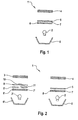
- FIG. 1 is a display device 1 in a schematic, cut Side view shown.
- a liquid crystal cell formed by an ESTN cell 4 of the display device 1 is by means of a light source 2 from one Side facing away from observer can be illuminated and x-rayed.
- a reflector 6 is arranged on the back of the light source 2.
- the light source 2 can directly load the liquid crystal cell 4, as shown shine through, or the light from the light source can be illuminated by means of a Light guide are supplied so that a lateral arrangement of the light source is possible.
- a diffuser formed by a diffuser 7 the rear with is provided with a leveling layer 8 which causes differences in brightness e.g. B. by a light spot formed with respect to the light source 2 - Reduced in the lighting level.
- the leveling layer 8 can be a halftone print.
- the diffuser 7 carries one on its front side Spectral filter 5, which is printed on the diffuser 7.
- FIG. 1 Another display device 1 with a first, designed as an ESTN cell Liquid crystal cell 4, which can be illuminated and transilluminated by means of a light source 2 and with a second liquid crystal cell 3 designed as a TN cell, which can be illuminated and illuminated by means of a light source 2 ', is shown in FIG Backs of the light sources 2, 2 'are reflectors 6, 6' and in the light path between the light sources 2, 2 'and the liquid crystal cells 4, 3 each have diffusers 7, 7 'arranged. On the back of the diffusers 7, 7 'are each with a Equalization layer 8, 8 'provided, and on its front, the liquid crystal cells 4, 3 facing, there are spectral filters 5, 5 '. It is different as shown - also conceivable that the spectral filters 5, 5 'and / or the diffusers 7, 7 'and / or the equalization layers 8, 8' each one Form part or element.
- the spectral filter 5 'shown in the left part of the display device 1 has a recess 11, wherein in the light path between the light source 2 'and the liquid crystal cell 3 corresponding to the recess 11 of the spectral filter 5 'a color filter 10, printed on a transparent support 9, arranged is.
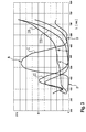
- a transmission diagram with transmission curves I, II, III, IV, each a spectral transmittance STG depending on the light wavelength ⁇ show is shown in Figure 3. It can be seen that a transmission curve II non-translucent sections of a TN liquid crystal cell a range B of minimal transmission of approximately 490 nm up to about 620 nm; towards lower and higher wavelengths however, the spectral transmittance STG increases significantly. The process is similar a transmission curve III of non-translucent sections an ESTN liquid crystal cell with a region C of minimal transmission from about 470 nm to about 600 nm; here too the spectral transmittance increases STG clearly towards lower and higher wavelengths on.
- a transmission curve I of a spectral filter has a maximum range
- a Transmission in areas B, C minimal transmission of the non-translucent switched sections of the TN and ESTN liquid crystal cells on; at lower and higher wavelengths is the spectral transmittance close to zero (areas D of minimum transmission of the spectral filter).
- the Light that has passed through the spectral filter therefore has wavelengths of in about 470 nm to about 580 nm and is not translucent by the switched sections of the liquid crystal cells completely blocked.
- the area A of maximum transmission of the transmission curve I of the spectral filter has a pronounced, broad maximum here, but could also be wavy and have several maxima.
- a transmission curve IV is translucent sections of the liquid crystal cells, wherein it can be seen that the spectral transmittance of these translucent switched sections in the relevant wavelength range specified by the spectral filter is substantially constant from about 470 nm to about 580 nm.
Landscapes
- Physics & Mathematics (AREA)
- Nonlinear Science (AREA)
- Liquid Crystal (AREA)
- Engineering & Computer Science (AREA)
- Mechanical Engineering (AREA)
- Mathematical Physics (AREA)
- Chemical & Material Sciences (AREA)
- Crystallography & Structural Chemistry (AREA)
- General Physics & Mathematics (AREA)
- Optics & Photonics (AREA)
- Details Of Measuring Devices (AREA)
Abstract
Description
- Fig. 1
- eine erfindungsgemäße Anzeigeeinrichtung mit einer Flüssigkristallzelle in schematisierter, geschnittener Darstellung,
- Fig. 2
- eine erfindungsgemäße Anzeigeeinrichtung mit zwei Flüssigkristallzellen in schematisierter, geschnittener Darstellung und
- Fig. 3
- ein Transmissionsdiagramm.
Claims (18)
- Anzeigeeinrichtung, insbesondere in einem Kraftfahrzeug, mit einer von einer Lichtquelle durchleuchtbaren Flüssigkristallzelle und einem in dem Lichtweg zwischen Lichtquelle und Flüssigkristallzelle angeordneten Spektralfilter, wobei die Transmissionskurve nicht lichtdurchlässig geschalteter Abschnitte der Flüssigkristallzelle im Wellenlängenbereich des sichtbaren Lichts einen Bereich eines Minimums oder mehrerer Minima und daran jeweils angrenzende Bereiche höherer Transmission aufweist, dadurch gekennzeichnet, daß die Transmissionskurve (I) des Spektralfilters (5) ein Maximum oder mehrere Maxima im Bereich (C) des Minimums bzw. der Minima der Transmissionskurve (III) der nicht lichtdurchlässig geschalteten Abschnitte der Flüssigkristallzelle (4) aufweist und außerhalb des Bereichs (C) des Minimums bzw. der Minima nahe null ist.
- Anzeigeeinrichtung nach Anspruch 1, dadurch gekennzeichnet, daß die Lichtquelle (6) ein breitbandiges Emissionsspektrum aufweist.
- Anzeigeeinrichtung nach einem der vorhergehenden Ansprüche, dadurch gekennzeichnet, daß die Flüssigkristallzelle (4) eine transflektive Zelle ist.
- Anzeigeeinrichtung nach einem der vorhergehenden Ansprüche, dadurch gekennzeichnet, daß der spektrale Transmissionsgrad lichtdurchlässig geschalteter Abschnitte der Flüssigkristallzelle (4) in dem Bereich (A) des Maximums bzw. der Maxima der Transmissionskurve (1) des Spektralfilters (5) in etwa constant ist.
- Anzeigeeinrichtung nach einem der vorhergehenden Ansprüche, dadurch gekennzeichnet, daß die Flüssigkritstallzelle (3) eine TN-Zelle ist.
- Anzeigeinrichtung nach einem der Ansprüche 1 bis 4, dadurch gekennzeichnet, daß die Flüssigkristallzelle (4) eine ESTN-Zelle ist.
- Anzeigeeinrichtung nach einem der vorhergehenden Ansprüche, dadurch gekennzeichnet, daß in dem Lichtweg zwischen Lichtquelle (2) und Flüssigkristallzelle (4) ein Diffusor (7) angeordnet ist.
- Anzeigeeinrichtung nach Anspruch 7, dadurch gekennzeichnet, daß der Spektralfilter (5) im Lichtweg zwischen Diffusor (7) und Flüssigkristallzelle (4) angeordnet ist.
- Anzeigeeinrichtung nach einem der vorhergehenden Ansprüche, dadurch gekennzeichnet, daß der Spektralfilter eine Scheibe mit einem Farbdruck aufweist.
- Anzeigeeinrichtung nach einem der vorhergehenden Ansprüche, dadurch gekennzeichnet, daß der Spektralfilter eine gegossene oder gespritzte oder gezogene Scheibe mit eingelagerten Farbpigmenten aufweist.
- Anzeigeeinrichtung nach Anspruch 9 oder 10, dadurch gekennzeichnet, daß die Scheibe eine Polymethylmethacrylat oder Polycarbonat aufweisende Kunststoffscheibe ist.
- Anzeigeeinrichtung nach einem der vorhergehenden Ansprüche, dadurch gekennzeichnet, daß der Spektralfilter ein Interferenzfilter ist.
- Anzeigeeinrichtung nach einem der vorhergehenden Ansprüche, dadurch gekennzeichnet, daß der Spektralfilter (5') eine Ausnehmung (11) aufweist.
- Anzeigeeinrichtung nach Anspruch 13, dadurch gekennzeichnet, daß im Lichtweg zwischen Lichtquelle (2') und Flüssigkristallzelle (3) korrespondierend mit der Ausnehmung (11) des Spektralfilters (5') ein Farbfilter (10) angeordnet ist.
- Anzeigeeinrichtung nach einem der vorhergehenden Ansprüche, dadurch gekennzeichnet, daß eine zweite Flüssigkristallzelle (3) vorgesehen ist, die entsprechend der ersten Flüssigkristallzelle (4) durchleuchtbar ist.
- Anzeigeeinrichtung nach Anspruch 15, dadurch gekennzeichnet, daß die erste Flüssigkristallzelle (4) eine ESTN-Zelle und die zweite Flüssigkristallzelle (3) eine TN-Zelle ist.
- Anzeigeeinrichtung nach Anspruch 15, dadurch gekennzeichnet, daß die erste Flüssigkristallzelle (4) eine DSTN-Zelle und die zweite Flüssigkristallzelle (3) eine TN- oder ESTN-Zelle ist.
- Anzeigeeinrichtung nach einem der vorhergehenden Ansprüche, dadurch gekennzeichnet, daß der Spektralfilter und die Flüssigkristallzelle ein einziges Bauteil bilden.
Applications Claiming Priority (4)
| Application Number | Priority Date | Filing Date | Title |
|---|---|---|---|
| DE10007461 | 2000-02-19 | ||
| DE10007461 | 2000-02-19 | ||
| DE10027635A DE10027635A1 (de) | 2000-02-19 | 2000-06-06 | Anzeigeeinrichtung |
| DE10027635 | 2000-06-06 |
Publications (2)
| Publication Number | Publication Date |
|---|---|
| EP1126311A2 true EP1126311A2 (de) | 2001-08-22 |
| EP1126311A3 EP1126311A3 (de) | 2003-11-05 |
Family
ID=26004409
Family Applications (1)
| Application Number | Title | Priority Date | Filing Date |
|---|---|---|---|
| EP01100644A Withdrawn EP1126311A3 (de) | 2000-02-19 | 2001-01-11 | Anzeigeeinrichtung |
Country Status (1)
| Country | Link |
|---|---|
| EP (1) | EP1126311A3 (de) |
Family Cites Families (6)
| Publication number | Priority date | Publication date | Assignee | Title |
|---|---|---|---|---|
| DE3237323A1 (de) * | 1982-10-08 | 1984-04-12 | Robert Bosch Gmbh, 7000 Stuttgart | Anzeigevorrichtung |
| DE3245931A1 (de) * | 1982-12-11 | 1984-06-14 | Licentia Patent-Verwaltungs-Gmbh, 6000 Frankfurt | Fluessigkristall-anzeigezelle |
| DE3310427A1 (de) * | 1983-03-23 | 1984-09-27 | Borg Instruments GmbH, 7537 Remchingen | Verfahren zum optimieren des kontrasts von feldeffekt-fluessigkristallzellen |
| IT1196057B (it) * | 1983-03-23 | 1988-11-10 | Borg Instr Gmbh | Dispositivo indicatore policromo a cristalli liquidi nonche' procedimento per ottimizzare il contrastro di celle a cristalli liquidi con effetto di campo |
| DE3643841A1 (de) * | 1986-12-20 | 1988-06-30 | Bosch Gmbh Robert | Anzeigevorrichtung mit fluessigkristallzelle |
| DE19704586A1 (de) * | 1997-02-07 | 1998-08-13 | Mannesmann Vdo Ag | Anzeigeeinrichtung mit einer Flüssigkristallzelle |
-
2001
- 2001-01-11 EP EP01100644A patent/EP1126311A3/de not_active Withdrawn
Non-Patent Citations (1)
| Title |
|---|
| None |
Also Published As
| Publication number | Publication date |
|---|---|
| EP1126311A3 (de) | 2003-11-05 |
Similar Documents
| Publication | Publication Date | Title |
|---|---|---|
| EP3570097B1 (de) | Bildschirm mit betriebsarten für eine freie und eine eingeschränkte sicht | |
| DE69715982T2 (de) | Anzeigevorrichtung | |
| DE60224206T2 (de) | Hintergrundbeleuchtung für transmissive anzeigen | |
| DE4426344C2 (de) | Anzeigeinstrument | |
| DE102017007669A1 (de) | Bildschirm für einen freien und einen eingeschränkten Sichtmodus und Verwendung desselben | |
| DE3233699C2 (de) | Fl}ssigkristall-Anzeigeeinrichtung | |
| EP2463152B1 (de) | Beleuchtungselement im Außenspiegel | |
| DE112019002950T5 (de) | Anzeigevorrichtung und Head-up-Display-Vorrichtung | |
| WO2000018609A1 (de) | Beleuchtbare anzeigeskalenvorrichtung | |
| DE10102774A1 (de) | Anzeigevorrichtung, insbesondere für ein Fahrzeug | |
| DE4334855A1 (de) | Anzeigevorrichtung für Kraftfahrzeuge | |
| WO2022029239A1 (de) | Vorrichtung zur anzeige von information, insbesondere für ein fahrzeug | |
| DE102022127222A1 (de) | Beleuchtungsvorrichtung für Fahrzeuge | |
| DE3803050C2 (de) | ||
| DE69405617T2 (de) | Anzeigesystem mit Hologramm, insbesondere zum Gebrauch bei Autoarmaturenbrettern | |
| DE10338691A1 (de) | Hintergrundbeleuchtung für Flüssigkristallanzeigen | |
| WO2024246124A1 (de) | Anzeigevorrichtung mit ir-kamera für ein fahrzeug | |
| DE102025106297A1 (de) | Anzeigevorrichtung | |
| EP1126311A2 (de) | Anzeigeeinrichtung | |
| EP1028348A1 (de) | Streuscheibe mit variabler Dicke | |
| DE2723483B2 (de) | Passive elektrooptische Anzeigeanordnung | |
| DE10027635A1 (de) | Anzeigeeinrichtung | |
| DE10141047B4 (de) | Spiegel, insbesondere Fahrzeugrückspiegel, und Verfahren zu seiner Herstellung | |
| DE102016007814B4 (de) | Bildschirm für einen freien und einen eingeschränkten Sichtmodus | |
| EP1063561A1 (de) | Flüssigkristallanzeige |
Legal Events
| Date | Code | Title | Description |
|---|---|---|---|
| PUAI | Public reference made under article 153(3) epc to a published international application that has entered the european phase |
Free format text: ORIGINAL CODE: 0009012 |
|
| AK | Designated contracting states |
Kind code of ref document: A2 Designated state(s): AT BE CH CY DE DK ES FI FR GB GR IE IT LI LU MC NL PT SE TR |
|
| AX | Request for extension of the european patent |
Free format text: AL;LT;LV;MK;RO;SI |
|
| RAP1 | Party data changed (applicant data changed or rights of an application transferred) |
Owner name: SIEMENS AKTIENGESELLSCHAFT |
|
| PUAL | Search report despatched |
Free format text: ORIGINAL CODE: 0009013 |
|
| AK | Designated contracting states |
Kind code of ref document: A3 Designated state(s): AT BE CH CY DE DK ES FI FR GB GR IE IT LI LU MC NL PT SE TR |
|
| AX | Request for extension of the european patent |
Extension state: AL LT LV MK RO SI |
|
| AKX | Designation fees paid |
Designated state(s): DE FR GB |
|
| STAA | Information on the status of an ep patent application or granted ep patent |
Free format text: STATUS: THE APPLICATION IS DEEMED TO BE WITHDRAWN |
|
| 18D | Application deemed to be withdrawn |
Effective date: 20040507 |