EP1126217A1 - Heat treating plant, installation method for porous regenerative element, production method for heat treated substance, selection method for porous regenerative element, and spent porous regenerative element component member - Google Patents
Heat treating plant, installation method for porous regenerative element, production method for heat treated substance, selection method for porous regenerative element, and spent porous regenerative element component member Download PDFInfo
- Publication number
- EP1126217A1 EP1126217A1 EP00956841A EP00956841A EP1126217A1 EP 1126217 A1 EP1126217 A1 EP 1126217A1 EP 00956841 A EP00956841 A EP 00956841A EP 00956841 A EP00956841 A EP 00956841A EP 1126217 A1 EP1126217 A1 EP 1126217A1
- Authority
- EP
- European Patent Office
- Prior art keywords
- porous
- regenerator
- regenerative
- direct
- heating chamber
- Prior art date
- Legal status (The legal status is an assumption and is not a legal conclusion. Google has not performed a legal analysis and makes no representation as to the accuracy of the status listed.)
- Granted
Links
Images











Classifications
-
- F—MECHANICAL ENGINEERING; LIGHTING; HEATING; WEAPONS; BLASTING
- F27—FURNACES; KILNS; OVENS; RETORTS
- F27B—FURNACES, KILNS, OVENS OR RETORTS IN GENERAL; OPEN SINTERING OR LIKE APPARATUS
- F27B19/00—Combinations of different kinds of furnaces that are not all covered by any single one of main groups F27B1/00 - F27B17/00
-
- F—MECHANICAL ENGINEERING; LIGHTING; HEATING; WEAPONS; BLASTING
- F28—HEAT EXCHANGE IN GENERAL
- F28D—HEAT-EXCHANGE APPARATUS, NOT PROVIDED FOR IN ANOTHER SUBCLASS, IN WHICH THE HEAT-EXCHANGE MEDIA DO NOT COME INTO DIRECT CONTACT
- F28D20/00—Heat storage plants or apparatus in general; Regenerative heat-exchange apparatus not covered by groups F28D17/00 or F28D19/00
- F28D20/0056—Heat storage plants or apparatus in general; Regenerative heat-exchange apparatus not covered by groups F28D17/00 or F28D19/00 using solid heat storage material
-
- F—MECHANICAL ENGINEERING; LIGHTING; HEATING; WEAPONS; BLASTING
- F23—COMBUSTION APPARATUS; COMBUSTION PROCESSES
- F23L—SUPPLYING AIR OR NON-COMBUSTIBLE LIQUIDS OR GASES TO COMBUSTION APPARATUS IN GENERAL ; VALVES OR DAMPERS SPECIALLY ADAPTED FOR CONTROLLING AIR SUPPLY OR DRAUGHT IN COMBUSTION APPARATUS; INDUCING DRAUGHT IN COMBUSTION APPARATUS; TOPS FOR CHIMNEYS OR VENTILATING SHAFTS; TERMINALS FOR FLUES
- F23L15/00—Heating of air supplied for combustion
- F23L15/02—Arrangements of regenerators
-
- F—MECHANICAL ENGINEERING; LIGHTING; HEATING; WEAPONS; BLASTING
- F23—COMBUSTION APPARATUS; COMBUSTION PROCESSES
- F23L—SUPPLYING AIR OR NON-COMBUSTIBLE LIQUIDS OR GASES TO COMBUSTION APPARATUS IN GENERAL ; VALVES OR DAMPERS SPECIALLY ADAPTED FOR CONTROLLING AIR SUPPLY OR DRAUGHT IN COMBUSTION APPARATUS; INDUCING DRAUGHT IN COMBUSTION APPARATUS; TOPS FOR CHIMNEYS OR VENTILATING SHAFTS; TERMINALS FOR FLUES
- F23L2900/00—Special arrangements for supplying or treating air or oxidant for combustion; Injecting inert gas, water or steam into the combustion chamber
- F23L2900/15021—Special arrangements for supplying or treating air or oxidant for combustion; Injecting inert gas, water or steam into the combustion chamber using regenerative heat exchanger bodies with different layers of material
-
- F—MECHANICAL ENGINEERING; LIGHTING; HEATING; WEAPONS; BLASTING
- F23—COMBUSTION APPARATUS; COMBUSTION PROCESSES
- F23L—SUPPLYING AIR OR NON-COMBUSTIBLE LIQUIDS OR GASES TO COMBUSTION APPARATUS IN GENERAL ; VALVES OR DAMPERS SPECIALLY ADAPTED FOR CONTROLLING AIR SUPPLY OR DRAUGHT IN COMBUSTION APPARATUS; INDUCING DRAUGHT IN COMBUSTION APPARATUS; TOPS FOR CHIMNEYS OR VENTILATING SHAFTS; TERMINALS FOR FLUES
- F23L2900/00—Special arrangements for supplying or treating air or oxidant for combustion; Injecting inert gas, water or steam into the combustion chamber
- F23L2900/15022—Special arrangements for supplying or treating air or oxidant for combustion; Injecting inert gas, water or steam into the combustion chamber using pre-purging regenerator beds
-
- Y—GENERAL TAGGING OF NEW TECHNOLOGICAL DEVELOPMENTS; GENERAL TAGGING OF CROSS-SECTIONAL TECHNOLOGIES SPANNING OVER SEVERAL SECTIONS OF THE IPC; TECHNICAL SUBJECTS COVERED BY FORMER USPC CROSS-REFERENCE ART COLLECTIONS [XRACs] AND DIGESTS
- Y02—TECHNOLOGIES OR APPLICATIONS FOR MITIGATION OR ADAPTATION AGAINST CLIMATE CHANGE
- Y02E—REDUCTION OF GREENHOUSE GAS [GHG] EMISSIONS, RELATED TO ENERGY GENERATION, TRANSMISSION OR DISTRIBUTION
- Y02E20/00—Combustion technologies with mitigation potential
- Y02E20/34—Indirect CO2mitigation, i.e. by acting on non CO2directly related matters of the process, e.g. pre-heating or heat recovery
-
- Y—GENERAL TAGGING OF NEW TECHNOLOGICAL DEVELOPMENTS; GENERAL TAGGING OF CROSS-SECTIONAL TECHNOLOGIES SPANNING OVER SEVERAL SECTIONS OF THE IPC; TECHNICAL SUBJECTS COVERED BY FORMER USPC CROSS-REFERENCE ART COLLECTIONS [XRACs] AND DIGESTS
- Y02—TECHNOLOGIES OR APPLICATIONS FOR MITIGATION OR ADAPTATION AGAINST CLIMATE CHANGE
- Y02E—REDUCTION OF GREENHOUSE GAS [GHG] EMISSIONS, RELATED TO ENERGY GENERATION, TRANSMISSION OR DISTRIBUTION
- Y02E60/00—Enabling technologies; Technologies with a potential or indirect contribution to GHG emissions mitigation
- Y02E60/14—Thermal energy storage
Definitions
- the present invention relates to a heat treatment equipment provided with a heating chamber having a plurality of regenerative combustors each provided with a direct-fired burner having a porous heat accumulating body built therein and applying a heat treatment to an object in the heating chamber; an installing method of a porous heat accumulating body when applying a heat treatment to the object in the heating chamber having a plurality of such regenerative combustors; and a manufacturing method of a heat-treated object using such a heat treatment equipment; a heat treatment equipment provided with a space in which a plurality of heat exchangers each having a built-in porous heat accumulating body are attached; an installing method of a porous heat accumulating body in such a heat treatment equipment; and a manufacturing method of a heat-treated object, using such a heat treatment equipment.
- the invention relates to a component member of a used porous heat accumulating body used so that the substantial average surface pore diameters of the porous heat accumulating bodies are not uniform for the plurality of direct-fired burners, or the plurality of regenerator combustors, or the plurality of heat exchangers.
- a heat treatment equipment which is provided with a heating chamber having a plurality of regenerative combustors or regenerative heat exchangers each having a regenerative burner having a built-in porous heat accumulating body, and applies a heat treatment to an object in this heating chamber.
- the porous heat accumulating body carries out heat exchange through alternate passage of a low-temperature gas and a high-temperature gas.
- the porous heat accumulating body is therefore exposed naturally to the severe heat shock environment, and also to a mechanical pressure caused by the passing gas under a thermal environment.
- the porous heat accumulating body may be exposed to severe chemical reactions. Therefore, the porous heat accumulating body is required to be made of a stable material capable of bearing use in such a severe environment.
- the service life of a porous regenerator used in a heat treatment equipment is not endless. Since it is used under severe conditions, it is inevitable to periodically or non-periodically replace the porous regenerator. The period of replacement becomes shorter also for other reasons.
- substances brought from outside the heat treatment equipment into the heating chamber exogenous off-purpose substances
- substances brought into the heating chamber from members within the heat treatment equipment including members themselves composing the porous regenerator
- endogenous off-purpose substances are subjected to a heat treatment in the heating chamber, or chemically react with environmental substances in the heating chamber, or materials themselves of the porous regenerator react with other substances in the heating chamber, resulting in by-products, or these off-purpose substances do not fully change into by-products and remain in the heating chamber temporarily or for a long period of time in the non-reacting form.
- the easiest method for preventing or inhibiting choking of the porous regenerator is to conduct maintenance works more frequently such as periodical or non-periodical inspection, maintenance, replacement, cleaning and the like of the porous regenerator, placing too much importance on safety of the heat treatment equipment, assuming from the very beginning a limited service life of the porous regenerator, i.e., a life shorter than the actual one. It is true that frequent maintenance works of the porous regenerator would solve the problem of choking.
- a typical example of endogenous off-purpose substances is a powdery or flaky residue produced as a result of wear or breakage of a porous regenerator through mechanical contact during service or an off-purpose substance produced as a result of application of a heat treatment to an object of treatment charged in a heating chamber.
- off-purpose substances coming from an object of treatment are oxides and other scale generated on the surface of the object of treatment as a result of a heat treatment in a heating chamber, comprising small particles separated from the object surface under the effect of mechanical pressure or heat shock of gases passing through the heating chamber or other environmental conditions (Japanese Unexamined Patent Application Publication No.7-119958).
- substances coming from component members of the porous regenerator (particularly, powdered substance described later) arranged in the former stage may be endogenous (exogenous in some configurations of the equipment) off-purpose substances for the porous regenerator arranged in the latter stage.
- Off-purpose substance remaining in the heating chamber may physically clog off pores of the porous regenerator after the lapse of some time. Softening, melting or evaporation caused by heat in the heating chamber (chemical reactions in a sense) may promote clogging of pores of this porous regenerator. A low-temperature gas flows through the regenerator. Particularly when discontinuing equipment operation for maintenance operation, there occurs a decrease in temperature of the regenerator. In such a case, the off-purpose substance having once softened, melted or evaporated hardens, solidifies or condenses, clogging off the pores of the porous regenerator, thus causing the "choking problem".
- By-products are considered in many cases to result from chemical reactions at least between two substances from among exogenous or endogenous off-purpose substances, materials of the porous regenerator (for example, small amounts of compositions or impurities) and environmental substances in the heating chamber. These chemical reactions must have an important correlation with heat treatment conditions in the heating chamber (for example, contents and composition of the burner fuel, heat treatment temperature and heat treatment atmosphere). When a reaction generating by-products occurs in a porous regenerator, particularly on the surface thereof, the by-products gradually clog up pores of the porous regenerator.
- this conventional art is a technology of transforming a surface layer of a porous regenerator guilt in a standalone regenerative burner or regenerative heat exchanger into a different shape or configuration, but has no relationship with a technical idea comprising contrivances about the form of a porous regenerator itself based on new findings about choking behavior in a plurality of regenerative burners or a plurality of regenerators in a regenerative heat exchanger.
- a first aspect of the present invention provides a heat treatment equipment comprising a heating chamber having a plurality of regenerative combustors having direct-fired burners each having a porous regenerator built therein; wherein the porous regenerators in the plurality of direct-fired burners or the plurality of regenerative combustors have different substantial average surface pore diameters.
- a sixth aspect of the invention provides an installing method of a porous regenerator built in a direct-fired burner provided in each of a plurality of regenerative combustors attached to a heating chamber in which a heat treatment is applied to an object carried in from outside; wherein the porous regenerators an installed in the plurality of direct-fired burners or regenerative combustors so that the substantial average surface pore diameters thereof are different from each other.
- a twelfth aspect of the invention provides an installing method of a porous regenerator in a heat treatment equipment provided with a space having a plurality of heat exchangers attached thereto each having built-in porous regenerator arranged along the flow direction of gas; wherein the porous regenerators are installed so that the substantial average surface pores of the porous regenerators in a plurality of heat exchangers are not uniform.
- a thirteenth aspect of the invention covers a manufacturing method of an object heat-treated in a heating chamber of a heat treatment equipment by operating the specific heat treatment equipment.
- This heat treatment equipment has a space in which a plurality of regenerative heat exchangers each having a built-in porous regenerator is arranged along the flow direction of gas, and setting is such that the substantial average surface pore diameter is not uniform for the porous regenerators in the plurality of regenerative heat exchangers.
- a heat treatment is applied to the object by arranging the object carried in from outside and/or carried out to outside in the heating chamber, thereby manufacturing the heat-treated object.
- a fourteenth aspect of the invention provides a heat treatment equipment provided with a heating chamber having a plurality of regenerative combustor each having a direct-fired burner having a built-in porous regenerator, wherein the substantial average surface pore diameter of the porous regenerators in the plurality of direct-fired burners or a plurality of regenerative combustors is larger for the one arranged at a lower position in the vertical direction.
- Fig. 1 is a schematic longitudinal sectional view illustrating a heating furnace.
- Fig. 2 is a schematic side view illustrating the heating furnace.
- Fig. 4 is a schematic plan view illustrating the arrangement of burners in the lower furnace of the heating furnace.
- Fig. 5 illustrates a direct-fired burner: (a) is a sectional view and (b) is a side view.
- Fig. 6 descriptive view of a unit cell of a honey-comb type regenerator: (a) is a perspective view of the regenerator; (b) is a perspective view of component members of the porous regenerator; and (c) is a descriptive view of the sectional area of a pore of the unit cell.
- Fig. 7 is a descriptive view of a unit cell of a ball type regenerator; (a) is a perspective view of the regenerator; (b) is a perspective view of the component members of the regenerator; and (c) is a descriptive view of a sectional area of a pore of the unit cell.
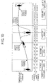
- Fig. 10 illustrates a temperature profile and charges thereof in a heating chamber of a heating furnace.
- Fig. 12 is a descriptive view of choking phenomenon in the lower furnace.
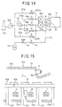
- Fig. 14 is a piping diagram of the direct-fired burner shown in Fig. 5.
- Fig. 15 is a partial sectional view of a walking beam type heating furnace.
- Fig. 16 is a descriptive view of an incinerating equipment: (a) is a side view, and (b) is a plan view.
- Fig. 20 is a schematic plan view illustrating the arrangement of burners in the upper furnace of another heating furnace.
- Fig. 21 is a schematic plan view illustrating the arrangement of burners in the lower furnace of another heating furnace.
- Fig. 24 illustrates the relationship between the choking rate or the regenerator replacement frequency and the operating time in another heating furnace.
- Fig. 25 is a descriptive view illustrating an arrangement of the regenerative combustors: (a) and (b) are plan views, and (c) and (d) are sectional views.
- Fig. 26 is a descriptive view illustrating another arrangement of the regenerative combustors: (a) and (b) are plan views, and (c) and (d) are sectional views.
- a honey-comb-shaped member itself has many pores, and can serve as a porous regenerator in the present invention.
- a collection of a plurality of honey-comb members as a whole as a regenerator for example, Japanese Unexamined Patent Application Publications Nos. 7-280239, 8-247671, and 7-39761, and Japanese Unexamined Utility Model Registration No. 7-2739
- the collection is recognized as a porous regenerator.
- a corrugated member for example, "Application of Performance and Reliability Concepts to Design of Ceramic Regenerator", published by Ford Motor Co., 1977).
- a regenerator comprising a honey-comb-shaped member, a corrugated member, or a collection thereof
- pores usually linearly pass through the body in the longitudinal direction, with a uniform cross-section in most cases, such as rectangular (for example, Japanese Unexamined Patent Application Publication No. 10-122517, Japanese Utility Model Registration No. 3049065) in many cases, but not limited to this, triangular (for example, Japanese Unexamined Patent Application Publication No. 55-46338), hexagonal (for example, Japanese Examined Patent Publication No. 7-39913), polygonal (for example, Japanese Unexamined Patent Application Publication No.
- a ball-shaped member is, on the other hand, only rarely used as a regenerator, and usually a collection of ball-shaped members is used as a regenerator (for example, Japanese Unexamined Patent Application Publications Nos. 10-176815, and 10-318529).
- a collection of ball-shaped members false pores are formed by connection of gap spaces between ball members.
- the false pores are not always linear in shape, and the cross-section is not constant, varying with the ball diameter, a combination of different ball diameters, or mixture of ball-shaped members of different shapes. This is also the case with mixture of ball-shaped members and honey-comb members (for example, Japanese Unexamined Patent Application Publications Nos. 7-127983 and 10-115408).
- pores may be linear, in an are a containing ball-shaped members, pores are not necessarily straight.
- a regenerator is formed by collecting many small-lump honey-comb members (for example, Japanese Unexamined Utility Motel No. 7-2739), although pores may be straight relative to individual members, non-linear false pores are formed by spatial connection of gaps between members.
- a regenerator having a plurality of false pores, provided with a porous structure falls under the category of porous regenerators.
- These porous regenerators having false pores formed therein shall be hereinafter referred to collectively as "ball type regenerators").
- honey-comb type regenerators because the small-lump honey-comb member itself acts as a honey-comb type regenerator, more accurately, such a honey-comb member falls under the category of honey-comb type regenerators.
- the member of pores or false pores should be at least two, not providing an upper limit.
- the standard is whether or not a factor is for the object, operation and advantages of the invention, to determine whether or not there are "many" pores or false pores.
- a porous regenerator is a structure to be incorporated into a prescribed place of prescribed equipment, there are imposed physical restrictions such as a certain volume, shape, size and weight, and furthermore, there should be required to exhibit desired quality and properties including mechanical strength, resistance to thermal shock and heat resistance within the range of these restrictions. Actually, therefore, the shape and size of pores in the sectional direction or in the longitudinal direction of pores of a porous regenerator or individual members forming the porous regenerator are not unlimited.
- regenerator having a catalytic function available (for example, Japanese Unexamined Patent Application Publications Nos. 7-127983 and 7-47233).
- a regenerator having a catalytic function available (for example, Japanese Unexamined Patent Application Publications Nos. 7-127983 and 7-47233).
- presence of such an additional function is not an important issue in the present invention.
- a regenerative heat exchanger means an apparatus which alternately conducts waste gas recovery of high-temperature gas and preheating of low-temperature gas by means of a regenerator by alternately switching over supply and discharge of a low-temperature gas and a high-temperature gas (for example, Japanese Unexamined Patent Application Publications Nos. 7-127983, 7-83585, 7-47233, 6-313508, 6-257972, 6-213585, and 5-340683 and Japanese Unexamined Utility Model Publication No. 7-2739).
- the direct-fired burner described later which is built by the combination of a combustion burner and a regenerative heat exchanger, can be considered to be a kind of regenerative heat exchanger. In any of the embodiments of the invention, however, it is not necessary that the regenerative heat exchanger is combined with a combustion burner as is a direct-fired burner described later.
- waste heat of the high-temperature combustion gas occurring from the combustion burner is collected through a regenerative heat exchanger combined therewith.
- the regenerative heat exchanger in this embodiment suffices to be installed in a space permitting heat exchange. It may be installed separately from the combustion burner, and it is not necessary to use the combustion burner as a heat source. Waste heat collection of the produced high-temperature gas may be achieved by means of a separate heat source (for example, Japanese Utility Model Registration No. 3049065).
- a direct-fired burner having a built-in regenerator means an apparatus which is formed by the combination of a combustion of combustion burner and generative heat exchanger (for example, Japanese Unexamined Utility Model Publication No. 7-2739) in which a gas in the site containing the object of treatment is movable through the regenerator.
- a combustion of combustion burner and generative heat exchanger for example, Japanese Unexamined Utility Model Publication No. 7-2739
- Typical examples of the "direct-fired burner having a built-in regenerator" in the present invention include the so-called regenerative alternate combustion burner which alternately conducts waste heat collection of combustion gas and preheating of combustion air through a regenerator connected to, or incorporated in, the combustion burner by alternately burning a pair of combustion burner (for example, Japanese Unexamined Patent Application Publications Nos.
- the above burner is limited to one having a structure in which gas in the site containing the object of treatment is movable through a regenerator, i.e., a "direct-fired burner". Therefore, a burner having a structure in which gas in the site containing the object of treatment does not move through a regenerator by using a heating tube or a radiant tube (for example, Japanese Unexamined Patent Application Publications Nos. 1-219412, 8-135936, 8-247420, 10-318528, and 10-115408) is not included in the category of "direct-fired burners" limited in an embodiment of the invention, irrespective of whether the type of combustion is regenerative alternate combustion or regenerative continuous combustion.
- a liquid, a solid or an emulsion may be mixed in a fuel.
- Air may be or may not be enriched with oxygen.
- the level of cleanliness of fuel or air pores no problem.
- regenerator is limited to a porous regenerator.
- a regenerative combustor having a direct-fired burner having a built-in regenerator means a combustor provided with a direct-fired burner having the above-mentioned built-in regenerator.
- the number of direct-fired burners forming a single regenerative combustor varies with the type of combustion of the direct-fired burner. For example, a pair of (two) regenerative alternate combustion burners, one regenerative continuous combustion burner, or a pair of (two) regenerative continuous combustion burners alternately burnt form a single regenerative combustor, respectively. If there are a pair of regenerative alternate combustion burner and a regenerative continuous combustion burner, there would be two regenerative combustors.
- Presence of a plurality of regenerative combustors includes at least the following types:
- Presence of a plurality of regenerative heat exchangers literally means presence of at least two of them. Since the regenerative combustor is an apparatus using porous regenerators as heat exchangers, it is included in the concept of "a heat exchanger having a built-in porous regenerator" in the claims of the present application, and the tenth to thirteenth and fifteenth aspects of the invention is construed with this concept in mind.
- Heating chamber having (a plurality of regenerative combustors or regenerative heat exchangers):
- heating chamber is a prescribed place, a space or a cell where a desired heat treatment is applied to an object of treatment, provided with a "heat treatment equipment” described later.
- a heating chamber is referred to as a combustion chamber in some cases (for example, Japanese Unexamined patent Application Publication No. 8-159664).
- the heat source used heat treatment is a direct-fired burner of a regenerative combustor.
- a regenerative heat exchanger not having a combustion burner is used.
- the place where the regenerative heat exchanger is to be installed is a place, a space or a cell where a heat exchange is conducted (hereinafter referred to as a "heat exchange chamber"), and is not required to be a prescribed place, space or cell where a desired heat treatment is applied to the object of treatment.
- the "space" having a plurality of regenerative heat exchangers in the tenth to thirteen aspects of the invention means a place, a space or cell expressing comprehensively a heat exchange chamber or the like discriminated from a heating chamber.
- the "gas" as used in the tenth to thirteenth aspects of the invention may be a gas discharged outside from the heating chamber where the heat treatment is applied to the object, or supplied from outside to the heating chamber, or may be a gas flowing from the heating chamber into the heat exchange chamber.
- the present invention is valid irrespective of the presence of a heating chamber, but since heat exchange is carried out by installing regenerative heat exchangers, it is quite natural that the invention is limited in terms of equipment. In the fifteenth aspect, therefore limitation covers up to the heat treatment equipment.
- Plurality of regenerative combustors are attached to the heating chamber for the purpose of achieving a desired temperature distribution in the heating chamber, and causing a change in time of this temperature distribution from time to time.
- a prescribed temperature history to the object of treatment, and thus to apply a desired heat treatment. For example, when carrying the object of treatment from outside into the heating chamber or carrying out the same from the heating chamber, the object of treatment is exposed to a steep temperature change.
- Thermal shock suffered from at this point may cause adverse effects on the subsequent heat treatment such as occurrence of a defect in the object, or adverse effects on the product quality of the heat-treated object.
- the operating conditions of the regenerative combustor are adjusted so that the temperature distribution in the heating furnace near the interface with outside changes slowly relative to the external temperature.
- the temperature distribution in the heating chamber is adjusted through adjustment of the operating conditions of the individual regenerative combustors.
- the heating chamber comprises connection of a plurality of unit cells, adjustment is made for each unit cell.
- Such adjustment can be accomplished static control in which the operating conditions of the individual regenerative combustors are kept constant, dynamic control in which, while measuring temperature by means of sensors provided outside the chamber or in the chamber or within the unit cells, or while monitoring operation of another regenerative combustor (for example, an adjacent regenerative combustor), the result is positively or negatively fed back, or any combination of static control and dynamic control.
- a computer in these controls in many cases, and if possible, a more primitive apparatus may be used for such control.
- attachment means arranging regenerative combustors or regenerative heat exchangers in general so that the gas in the heating chamber or the gas used for heat exchange is movable through the regenerators. More specifically, not limitative, “attachment” is a kind of installing combustors in the heating chamber. So far as combustors or heat exchangers are installed in the heating chamber so that in the presence of the object, specifically, the gas in the heating chamber becomes movable through the regenerators any method may be adopted, irrespective of the distance between the object of treatment and the regenerators arranged in the heating chamber or the form of the gas channel connecting the both.
- it means arranging the regenerative combustors or the regenerative heat exchangers in a state in which the gas in the space formed by the heating chamber is movable through the regenerators. It includes arranging the same so that the regenerators face the space formed by the heating chamber, and arranging the same so that the regenerators face the space formed by the gas channel attached to the heating chamber, as well as arranging the same in a manner in which all or part of the main bodies of the combustors or the heat exchangers are buried in the wall of the heating chamber, and arranging the same while connecting main bodies of the combustors or the heat exchangers to the heating chamber with piping or gas channels.
- the flow-direction of the gas flowing through the porous regenerators of the regenerative combustor or the regenerative heat exchanger may be constant or may be reversed. For example, even when the regenerative combustor attached to the heating chamber performs alternate combustion, if the gas outside the heating chamber flows into the heating chamber and the gas in the heating chamber flows out to outside, it is not necessary to reverse the direction of the gas flow in the regenerators. If contrivances are made in the gas piping and switching thereof, the flow. channel of the gas flowing from outside the heating chamber into the heating chamber and the position of passage through the regenerators can be changed with a constant gas flow direction through the regenerators or without changing it into another direction or reversing the same.
- the flow channel of the gas flowing from outside the heat exchange chamber into the heat exchange chamber and the position of gas passage through the regenerators can be changed with a constant gas flow direction through the regenerators or without changing it into another direction or reversing the same.
- Types of arrangement of the plurality of regenerative combustors and/or regenerative heat exchangers include, for example, a type of array arrangement in the moving direction of the object of treatment (for example, Japanese Unexamined Patent Application Publications Nos. 7-4853, 8-210780 and 7-97617), a type of arranging the same on a wall (usually the furnace wall) forming the space in the heating chamber so as to surround that internal space (for example, Japanese Unexamined Patent Application Publication No. 6-94368), a type arranging the same in a path or a separate space corresponding to the path of the gas discharged from the heating chamber to outside (for example, Japanese Unexamined Patent Application Publication No.
- the array arrangement types there is available a type of arranging in series a plurality of units or a plurality of zones with a group several regenerative combustors and/or regenerative heat exchangers (including a single case) as a unit or as a zone (for example, Japanese Unexamined Patent Application Publications Nos. 6-200329, 8-20934, 6-238317, 7-97617, and 8-159453).
- the type of arrangement in the invention is not limited to the above, but a type of arrangement in which burner flame axes cross and various other types of arrangement are widely covered.
- heating treatment equipment means any furnace to which the present invention is applicable or which is not excluded from application of the invention.
- a heating furnace for example, Japanese Unexamined Patent Application Publication No. 6-238317
- an incinerating furnace for example, Japanese Unexamined Patent Application Publication No. 10-197159
- an ash melting furnace for example, Japanese Unexamined Patent Application Publication No. 8-68519
- a melting furnace for example, Japanese Unexamined Patent Application Publication No. 10-246585
- a heat treatment furnace for example, Japanese Unexamined Patent Application Publication No.
- a heat treatment equipment comprises an entry and a carry-in path into which an object of treatment is carried from outside in heating chamber (i.e., a route through which the object of treatment is carried in), an entry section (an area including the entry and the proximity thereof) directly connected to the carry-in path provided in a heating chamber of the heat treatment equipment, an exit and a carry-out path for carrying out the object of treatment subjected to the heat treatment from the heating chamber to outside (i.e., the route through which the object of treatment is carried out), and an exit section (i.e., an area including the exit and the proximity thereof) in some heating chambers.
- An opening/closing door or an opening/closing apparatus may be provide in the carry-in path or the carry-out path (for example, Japanese Unexamined Patent Application Publication No. 6-238317).
- the heating chamber after carrying in the object of treatment in the heating chamber by opening the door on the carry-in path side, the heating chamber is isolated from outside by closing the door, and after carrying out the object of treatment subjected to a heat treatment to outside by opening the carry-out path side door, the heating chamber is isolated from outside.
- a gas channel (i.e., the route through which a gas flows) connecting the interior of the heating chamber to outside is provided, and there is a gas channel port provided (i.e., an area including an exit connecting the interior of the heating chamber to outside from among the routes through which gas flows and the proximity thereof or an entry and the proximity thereof) directly connected to the gas channel in the heating chamber.
- a gas channel include a chimney, a flue and a duct for discharging the gas in the heating chamber to outside.
- This gas channel may be provided with an apparatus which connects the heating chamber to outside from time to time such as an opening/closing door or an opening/closing valve.
- the heating chamber is connected to outside as required by means of a dumper provided in the chimney or the like to control the gas pressure or specific gas partial pressure in the heating chamber by exhausting (for example, Japanese Unexamined Patent Application Publications Nos. 6-238317, 7-103361, 8-210780 and 6-200329).
- the carry-in path or the carry-out path of the object of treatment forms a separate space from the internal space of the heating chamber in some cases (for example, Japanese Unexamined Patent Application Publications Nos. 8-210780, 7-258740, and 8-135936), or are integrated with the internal space of the heating chamber so that it is impossible to discriminate (for example, Japanese Unexamined Patent Application Publications Nos. 7-103659 and 6-200329).
- Japanese Unexamined Patent Application Publications Nos. 7-103659 and 6-200329 for example, Japanese Unexamined Patent Application Publications Nos. 7-103659 and 6-200329.
- the entry through which the object of treatment is carried from outside into the heating chamber and the entry section which should be in the heating chamber are very close to each other and have a so-called back-to-back positional relationship. This is also the case with the relationship between the exit through which the object is carried from the heating chamber to outside and the exit section which must be in the heating chamber.
- the carry-in path and the carry-out path can actually be confined, or whether or not configuration is limited to only conceptual one.
- the "path” is a route through which a substance or an object passes
- the "pass port” is an exit or an entry connecting a space and a separate space in a route crossing a plurality of spaces.
- the above-mentioned carry-in path, carry-out path, gas channel, entry section, exit section and gas channel port may be considered to fill under the category of paths and path ports in view of there functions.
- the paths include the carry-in path, the carry-out path and/or the gas channel
- the path ports include the entry section, the exit section and/or the gas channel, unless otherwise discriminated by clear specification.
- the object to be treated and the object mean an object to be heat-treated or a heat-treated object, unless otherwise discriminated by clean specification.
- object of treatment or object include metal ores, a slab, a bullet and other pieces of steel (for example, Japanese Unexamined Patent Application Publications Nos. 7-258740 and 8-143949), a metal strip (for example, Japanese Unexamined Patent Application Publications Nos. 8-159664 and 7-102326), a steel section (for example, Japanese Unexamined Patent Application Publications Nos. 7-97617 and 6-200328), incineration ash (for example, Japanese Unexamined Patent Application Publication No.
- substantially average surface pore diameter of a porous regenerator is a term specifically defined in the present specification, and will be described later in detail.
- the M porous regenerators are divided into P(2 ⁇ P ⁇ M) groups taking different values of substantial average surface pore diameter (even a single porous regenerator taking a value is counted as a group);
- All the M porous regenerators take values different from each other of the substantial average surface pore diameter.
- porous regenerators belonging to different direct-fired burners or heat exchangers, and if there exist porous regenerators having a substantial average surface pore diameter small or larger than the others, the substantial average surface pore diameters of the porous regenerators may be considered "not uniform" in the invention.
- Fig.1 is a schematic longitudinal sectional view illustrating a heating furnace
- Fig. 2 is a schematic side view illustrating the heating furnace
- Fig. 3 is a schematic plan view illustrating a heating furnace having an upper burner shown
- Fig. 4 is a schematic side view illustrating the heating furnace having a lower burner shown.
- Fig. 1 represents a heating furnace main body; 2a and 2b, direct-fired burners; 3a and 3b, regenerators; 4a and 4b, fuel cut-off valves; 5, four-way valve for switching over between supply of fuel air and suction of combustion waste gas; 6, combustion waste gas exhaust port; and 7, an object of treatment such as a steal plate.
- the temperature of combustion air fed to the regenerator 3a for example, 30°C, and this air is heated by the regenerator 3a into preheated air at 1,250°C, which is fed to the burner 3a.
- Preheated air is burnt together with a combustion gas and fed to the heating furnace main body 1.
- a part of the combustion waste gas is sucked into the regenerator 3b at 1,350°C via the burner 2b, heats the regenerator 3b, and is discharged as combustion waste gas at 200°C.
- the balance of combustion gas is discharged from the exhaust port 6 to outside the furnace.
- Switching between the burners 2a and 2b is conducted in linkage with switching between the fuel cut-off valves 4a and 4b and the combustion air and combustion waste gas switching four-way valve 5.
- the switching period (alternating period) of the burners 2a and 2b should preferably be a high frequency of the order from about 10 to 30 seconds, but this is not limitative.
- the heat recovery efficiency is improved by incorporating a waste heat recovery system based on repetition of heat accumulation and heat dissipation in a short period of time and providing regenerators 3a and 3b.
- the regenerators 3a and 3b should preferably be structures which have a large heat exchanging area per unit volume, a large gas passage area, and a small pressure loss upon passage of a fluid.
- a honey-comb structure is suitable.
- a honey-comb type regenerator is used for the direct-fired burner.
- a ceramic material not melting at a high temperature is used as a material for the honey-comb type regenerator because a combustion gas at a high temperature of over 1,300°C passes therethrough.
- Such a ceramic honey-comb is manufactured by sintering an extrusion-formed material. Therefore, the sectional shape of honey-comb in a regenerator made of a ceramic honey-comb is constant in the flow direction.
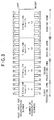
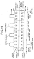
- the above-mentioned burners are arranged in two stages including upper and lower ones with an object path in between: A1 to A19 are upper burners and B1 to B19 are lower burners.
- the area covering A1 to A3 and B1 to B3 is the first preheating zone; the area covering A4 to A8 and B4 to B8 is the second preheating zone; the area covering A9 to A13 and B9 to B13 is the heating zone; and the area covering A14 to A19 and B14 to B19 is the soaking zone.
- the flue shown in Fig. 3 serves as the aforementioned combustion waste gas exhaust port 6, and can be opened or closed by a dumper.
- a typical example of the heating furnace is a heating equipment for steel, and particularly, an equipment using the by-product gas from a blast furnace as fuel is suitable.
- contrivances are made in the form of the porous regenerators contained in the direct-fired burners or the regenerative combustors or the regenerative heat exchanger arranged in areas where materials causing choking tend to deposit so that such materials becomes hard to deposit or choking phenomenon does not become apparent even upon deposit. It is thus possible to prevent or inhibit occurrence of various problems caused by choking.
- the porous regenerators built in the direct-fired burners, the regenerative combustors or the regenerative heat exchangers are uniform in terms of the substantial average surface pore diameter so as to decelerate the progress of choking phenomenon as a whole for the porous regenerators arranged in areas where choking tends to occur relatively easily.
- the porous regenerators in the direct-fired burners or the regenerative heat exchangers arranged in an area near the path port through which exogenous off-purpose substances come in (referred to as the "first area” in the fourth, seventh and ninth aspects of the invention; and referred to as “the first area” and “the second area” in the fifth aspect of the invention) than in those arranged in the other area (referred to as the "second area” in the fourth, seventh and ninth aspects of the invention; and referred to as the "third area” in the fifth aspect of the invention).
- exogenous off-purpose substances promote choking most actively, followed by endogenous off-purpose substances, and/or endogenous off-purpose substances tend to easily occur near the path port where there is a large temperature difference between outside and the interior of the heat treatment equipment.
- the progress of choking in the porous regenerators contained in the direct-fired burners or the regenerative heat exchangers is more rapid in the area closer to the entry section through which the object of treatment is carried in from outside (referred to as the "first area” in the fifth aspect of the invention) than in the area closer to the exit section through which the object is carried out (referred to as the "second area” in the fifth aspect of the invention).
- first area in the fifth aspect of the invention
- second area in the fifth aspect of the invention
- the "remaining area” can be set depends upon the shape of the heating chamber (particularly, the length forming the path, a structure causing a change in the flow rate of the gas in the chamber, or the presence of a structure causing a sudden temperature difference), or whether or not there is a path port other than the exit section and the entry section, and eventually various with the kind, features and other conditions of the heat treatment equipment.
- Another conceivable cause is the temperature difference.
- the temperature difference In the areas near the entry section and near the exit section, the temperature difference is large with outside.
- a lower-temperature open air comes in the heat treatment equipment rather than discharge of the high-temperature gas in the interior to outside.
- the high-temperature gas In the exit section, in contrast, the high-temperature gas is discharged outside rather than inflow of the open air.
- the temperature difference causing occurrence of endogenous off-purpose substances is therefore large in the entry section. As a result, progress of choking is considered to be more rapid in the area closer to the entry section.
- porous regenerator Another conceivable cause of choking phenomenon in porous regenerator is gravity. Since a gas flow is formed in the heating chamber, fine particles or lightweight target substances are blown off under the effect of gas pressure and estimated to scatter in diverse and various directions. However, because gravity acts more or less on exogenous or endogenous off-purpose substances, these substances tend to move from up to down basically under the effect of action of gravity irrespective of the presence of the heating chamber. Therefore, a porous regenerator arranged at a lower position is more susceptible to choking. For example, in the heating furnace shown in Figs. 2 to 4, at the same horizontal position, choking is more easily caused in the lower burner than in the upper burner.
- a heat treatment equipment of a kind for example, waste incinerating facilities
- contribution to choking phenomenon in porous regenerators of regenerative burners or regenerative heat exchangers is larger for endogenous off-purpose substances than for exogenous off-purpose substances.
- This is considered attributable to the fact that, since off-purpose substances produced in the heating chamber of the incinerator having a temperature far higher than that outside is huge in quantity and in the form of fine particles, it is difficult to completely remove such substances. Therefore, endogenous off-purpose substances serving to cause choking are larger in. quantity than exogenous off-purpose substances.
- porous regenerator arranged on the higher-temperature side or in the upstream in the gas flow direction is more easily susceptible to choking phenomenon.
- Such a heat treatment equipment is the heat treatment equipment intended by the present invention.
- By-products which are materials causing choking other than exogenous and endogenous off-purpose substances basically cause choking in porous regenerators in which choking is caused by exogenous and endogenous off-purpose substances. They therefore promote progress of choking phenomenon, together with the exogenous and/or endogenous off-purpose substances, in an area near the path port, an area in the upstream of the gas flow, an area where a large temperature difference occurs, an area where the gas flow temperature is higher, an area where a large temperature difference occurs, and an area closer to the exit section than the entry section.
- areas in which choking tend to easily occur can be specified as follows: (1) an area where there is a path port opening or capable of opening toward outside, and an area where a steep temperature gradient is impressed; (2) when off-purpose substances are carried by the gas flow, an area located more in the upstream of the gas flow, or an area where a gas of a higher temperature flows; and (3) an area located at a lower position in the vertical direction where off-purpose substances can easily move in accordance with the natural law.
- the areas in the uppermost stream and the lowermost stream of the gas flow are areas opening or capable of opening toward outside where temperature is higher than outside and the temperature gradient tends to change suddenly.
- the path port of (1) can be divided into an entry section, an exit section, and other path port, and choking tend to easily occur in the entry section and an area closer thereto, the exit section and an area closer thereto, and path port other than the above and an area closer thereto in this order.
- the regenerative combustor comprises a pair of direct-fired burners performing alternate combustion, or in a regenerative heat exchanger in which the gas performs heat exchange through a pair of porous regenerators while alternately changing the flowing direction, or in a pair of regenerative combustors performing alternate combustion
- Even a case where the substantial average surface pore diameter is not uniform between these at least two (particularly only two) porous regenerators is included within the scope of the present invention and is not excluded therefrom.
- a pair C1 and C1, a pair C2 and C2, a pair D1 and D1 and a pair D2 and D2 are, respectively, a pair of direct-fired burners performing alternate combustion, a pair of heat exchangers through which the gas flows alternately, and a pair of regenerative combustors performing alternate combustion.
- the X-direction is on the path port side, the upstream side of the flowing gas, or the high-temperature side
- the Y-direction shows the side of area more distance from the path port side, the downstream side of the flowing gas or the low-temperature side.
- setting is made so that the substantial average surface pore diameter is different between the porous regenerators on the X side C1 and C2 and C1 and C2 on the Y side.
- the substantial average surface pore diameter for the former is set to be larger than that of the latter.
- setting is made so that the substantial average surface pore diameter is different between the porous regenerators of D1 and D2 attached to the lower chamber and those of D1 and D2 attached to the upper chamber in Fig. 25(c) and 25(d).
- the substantial average surface pore diameter for the former should be larger than those for the latter.
- the invention does not exclude areas based on such combination from the technical scope thereof, as described below.
- the first to ninth aspects of the invention correspond to (1) above in a heat treatment equipment having a heating chamber; the third, seventh and ninth aspects of the invention described (1)above more specifically; and the fourth and fifth aspects of the invention describe them further in detail.
- the tenth to thirteenth aspects of the invention corresponds to (2) above, in a heat treatment equipment having a heating chamber and a space other than the heating chamber (for example, a heat exchange chamber), and the twelfth aspect of the invention corresponds to a specific description thereof in detail.
- the fourteenth aspect of the invention corresponds to (3) above in a heat treatment equipment having a heating chamber, and the fifteenth aspect of the invention corresponds to (3) above, irrespective of the presence of a heating chamber, a heat exchange chamber or the like.
- Figs. 2 and 3 illustrate a schematic longitudinal sectional view and a schematic cross-sectional view of a heating furnace, a type of the heat treatment equipment of the invention, respectively.
- areas of the heating chamber near the carry- in door and the carry-out door of an object correspond to the entry section and the exit section, respectively.
- the carry-in door and the carry-out door are opened only when the object is carried in from outside toward the entry section and when the object is carried out from the exit section to outside, and are closed for all the other cases.
- the heating chamber serves as the nucleus of the heating furnace, and can be divided into an upper furnace comprising upper burners A1 to A19 and a lower furnace comprising lower burners B1 to B19.
- the upper furnace and the lower furnace each comprises 19 pairs of upper and lower burners.
- the four zones including a first preheating zone, a second preheating zone, a heating zone and a soaking zone shown in Figs. 2 and 3 are achieved on the basis of differences in heat treating conditions, particularly heat input conditions for each of the upper furnace and the lower furnace shown in the drawings as examples.
- the heating chamber in the heating furnace can be considered as comprising four cells, or as four heating chambers connected.
- Figs. 2 to 4 illustrate a case where the direction of flame of the direct-fired burner (burner axis) is perpendicular to the object moving direction, but this is not intended to exclude a case where the burner axis is in parallel with the object moving direction (for example, Japanese Unexamined Patent Application Publications Nos. 8-210780 and 7-97619).
- the present invention covers a case where the burner axis is not perpendicular to the object moving direction.
- the substantial average surface pore diameter in the present invention is an evaluation index defined for objectively determining the choking phenomenon as far as possible. More specifically, without the intention to limit the invention, the substantial average surface pore diameter is the size of pores (including false pores) of a regenerator defined in the surface layer ranging from the surface of a porous regenerator to a certain depth. In the present invention, however, as described later, parameters having a correlation with the progress of choking phenomenon, such as changes in pressure or pressure loss of the gas passing through the porous regenerators of the burners, which are irrelevant at first sight to the size of pores of the regenerators, are not excluded from the definition of the substantial average surface pore diameter.
- Choking phenomenon of porous regenerator may primarily be considered a choking caused by deposition of off-purpose substances onto interior of pores. This choking, if observed for a long period of time, may be considered as a phenomenon over the entire interior surface of a pore in a regenerator. An actual choking phenomenon, however, occurs in the surface layer from the surface of the porous regenerator up to a certain depth. Choking of the surface layer therefore becomes so serious that the porous regenerator is not usable when choking progresses over the entire internal surface of the pore. Whether or not choking has progressed so as to make it impossible to use may be determined within a range of from several cm to 10 cm from the regenerator surface.
- the by-product generated from a reaction between the regenerator and an off-purpose substance it should be set within a range of about 10 cm from the surface layer.
- the substantial average surface pore diameter should be set within, for example, a range of from several cm to 10 cm.
- the substantial average surface pore diameter may be determined by sampling several constituent members present within the surface layer thickness range set as above.
- the substantial average surface pore diameter is determined by sampling honey-comb constituent members from a first stage (2.5 cm) or first and second stages (5 cm) on the top side (high-temperature side) of a honey-comb regenerator comprising 2.5 cm-high honey-comb constituent members piled into multiple stages.
- the substantial average surface pore diameter is defined by setting thickness for individual surface layers taking account of the extent and details of choking, kinds of substances in question causing choking, staging state of regenerator constituent members and the like.
- the state in which choking has progressed to such an extent as not permitting use is not a state in which pores are completely choked by deposition of off-purpose substances, but a state of choking of pores to such an extent that a certain past level has been reached.
- Progress of pore choking causes an increase in the pressure of gas passing through the regenerator, and poses problems in heat treatment equipment stability and safe operation.
- frequent inspection and replacement of the regenerators to solve choking of pores lead to an increase in equipment management cost.
- the "certain level" for comparison with the pore choking state is set as a critical value empirically selected as a harmony point of these mutually contrary demands.
- ⁇ The simplest index of quantitatively evaluating the choking phenomenon is the choking rate ( ⁇ ) of pore. This can be defined as a ratio of a change in sectional area of the initial pore to the pore suffering from choking.
- Fig. 6 shows, from among regenerator constituent members (Fig. 6(b)) forming a part of a gas passage end face of a honey-comb type regenerator (Fig. 6(a)), when adopting an arbitrary unit cell Cm, the sectional area Sc of pores forming such a unit cell Cm (Fig. 6(c)).
- the unit cell section is drawn as a square.
- the section of the unit cell is not limited to a square, but may be a substantial semi-circular, rectangular, circular or any other shape.
- a unit cell or pores forming a unit cell may be primarily determined.
- a ball type regenerator in which pores, i.e., false pores, not comprising straight pores, are formed by connecting gaps between balls in a lump comprising many balls, it is not so easy as in the case shown in Fig. 6 to define a unit cell or the sectional area, i.e., the choking rate, of pores forming a unit cell. If a ball type regenerator is a collection of spherical members of the same size, it could relatively define it easily in a geometrical manner. However, definition is difficult when a regenerator is a collection of constituent members of different shapes.
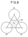
- Fig. 7 illustrates a ball type regenerator permitting relatively easy setting of Qm and Sq.
- the surface layer comprises six layers P1 to P6 (Fig. 7(a)). Constituent members are regularly arranged on each layer. The individual layers are laminated with regular spatial phase shifts (Fig. 7(b). As a result, the unit cell Qm forms ideally a square (a, b, c and d), and Sq is obtained by subtracting sectional area cut along the equatorial line of the balls which are constituent members (Fig. 7(c)).
- Fig. 9 is a schematic view of the progress of choking in a unit cell.
- Fig. 9(a) relates to the unit cell Qm
- Fig. 9(b) relates to a unit cell Cm.
- the amount of deposited off-purpose substances increases with the lapse of time t, and finally, a choking rate not permitting further use (critical choking rate) is reached.
- This final stage is a timing for replacement of the porous regenerators in the heat treatment equipment, which means the expiration of the service life (critical life) of the porous regenerator.
- the value of sectional area of pores of a unit cell (Sc(t), Sq(t): t ⁇ 0) set in relation to pores and false pores in terms of choking phenomenon can be defined as the substantial average surface pore diameter of porous regenerator.
- a useful method for comparing these pores having different natures is to pay attention to the pressure or pressure loss of the gas flowing through the regenerator or changes therein. For example, it would be rational to evaluate choking to pay attention to the parameter of pressure loss, not a parameter of the substantial average surface pore diameter, and compare pores and false pores both having a pressure loss on the same level.
- the fourth aspect of the invention covers an embodiment in which ball type regenerators are arranged in the first area closer to the path port and honey-comb type regenerators, in the other areas.
- the fifth aspect of the invention covers an embodiment in which ball type regenerators are arranged in the entry section or the first area near the entry section, and honey-comb type regenerators, in the other second and third areas.
- the tenth aspect of the invention covers an embodiment in which ball type regenerators are arranged in the upstream of the gas flow, and honey-comb regenerators, in the downstream.
- the fifteenth aspect of the invention covers an embodiment in which honey-comb type regenerators are arranged in the upper portion in the vertical direction, and ball type regenerators, in the lower portion thereof.
- Fig. 10 illustrates a temperature profile achieved in the heating chamber under the heat input conditions shown in Figs. 2 and 3 as examples.
- the object moving in the heating furnace is subjected to a heat treatment corresponding to this temperature profile and to a sudden heating as shown by [B] over the range from the latter half of the second preheating zone to the heating zone.
- [B] a sudden heating as shown by [B] over the range from the latter half of the second preheating zone to the heating zone.
- Fig. 12 illustrates the choking problem of the porous regenerator encountered in the lower furnace as a result of actual operation of the heating furnace.
- Figs. 11 and 12 show result of operation simultaneously by operating the same heat treatment equipment under the same conditions. It is known from these drawings that choking occurring in the upper furnace similarly occurs in the lower furnace. The conclusion reached in Fig. 11 about the critical service life of the regenerator applies in the same manner qualitatively also to the lower furnace.
- Fig. 13 illustrates the result of a more minute analysis of the choking phenomenon of the porous regenerators in the upper furnace and the lower furnace.
- Fig. 13 also explains the method of setting a substantial average surface pore diameter for preventing or inhibiting choking. It is known from Fig. 13 that the critical service life of the regenerator largely differs between areas B11 to B13 and areas A11 to A13, and for the other areas, there is no marked difference between the upper furnace and the lower furnace, although the critical service life of regenerator is basically shorter for the lower furnace than for the upper furnace. This is attributable to the effect of gravity acting on the off-purpose substances in the heating chamber. The difference between areas B11 to B13 and areas A11 to A13 is markedly larger than in the other areas, perhaps due to opening of the dumper in the flue.
- Fig. 13 serves also as a descriptive view of the method of setting a substantial average surface pore diameter for preventing or inhibiting the choking phenomenon.
- FIG. 5 11 represents a burner; 12, the burner main body of the burner 11, comprising a known refractory material; 13a, a first air channel; 13b, a second air channel; these air channels 13a and 13b are formed so as to pass through the burner main body 12 in the front/back direction; 14a and 14b, regenerators comprising honey-comb type promeric members made of a refractory material such as ceramics or container-shaped promeric members containing many ceramic pellets, housed in regenerating boxes 16a and 16b, respectively, connected to air channels 13a and 13b via connecting tubes 15a and 15b.
- the regenerating boxes 16a and 16b are separated from each other in Fig.
- housing sections of respective regenerators 14a and 14b may be formed by dividing one regenerating box with a partition.
- 17 represents a central air channel, formed so as to pass through the burner main body 12 between the air channels 13a and 13b, having a connecting tube 18 at the rear end thereof; 19, a fuel nozzle passing through the rear end of the connecting tube 18 and inserted into the center air channel 17; and 110, a flame monitoring window, provided on a side of the central air channel 17.
- the burner 11 having such a configuration is attached to the furnace wall toward the interior of the heating chamber or the furnace with both the air channels 13a and 13b to which pipes are connected as shown in Fig. 14.
- a fuel nozzle 19 is connected to a gas source 114 via a gas feed line 113 having a cut-off valve 111 and a regulating valve 112.
- the connecting tube 18 of the central air channel 17 is connected to an air feeder 117 via an air feed line 116 having a cut-off valve 115.
- the connecting tube 15a of the first air channel 13a is connected to the air feeder 117 via an air feed line 119a having a change-over valve 118a, and connected to an induction fan 122 via a waste gas line 121a having a change-over valve 120a.
- the connecting tube 15b of the second air channel 13b is connected to the air feeder 117 via the air feed line 119b having a change- over valve 118b, and connected to the induction fan 122 via the waste gas line 121b having a change-over valve 120b.
- the burner 11 connected as described above is operated in any of two operating modes corresponding to opening/closing of the four change-over valves 118a, 118b, 120a and 120b alternatively and repeatedly every prescribed period of time on the basis of an external control signal.
- the first operating mode the change-over valves 118a and 120b are opened and the change-over valves 118b and 120a are closed.
- the second operating mode corresponds to just a reversed case.
- a fuel gas is fed from the gas source 14 to the combustion nozzle 19 via the gas feed line 113, and a part of combustion air is fed from the air feeder 117 to the central air channel 17 via the air feed line 116.
- combustion air is supplied from the air feeder 117 to the first air channel 13a via the air feed line 119a, and thus supplied combustion air is mixed with the aforementioned fuel gas and burned to flame F.
- Waste gas in the heating chamber or the furnace is sucked from the second air channel 13b into the waste gas line 121b, driven by the induction fan 122, and discharged into the open air from the chimney 123. Further, it is heated through contact with high-temperature waste gas passing through the regenerator 14b of the connecting tube 16b.
- combustion air is supplied from the air feeder 117 to the second air channel 13b through the air feed line 119b, and this combustion air is mixed with the above-mentioned fuel gas and burned to form the flame F.
- Waste gas in the heating chamber or the furnace is sucked from the second air channel 13a into the waste gas line 121a, driven by the induction fan 122, and discharged into the open air from the chimney 123.
- regenerator 14b It is furthermore heated through contact with high-temperature waste gas passing through the regenerator 14a of the connecting tube 16a.
- the regenerator 14b is thus heated in the first operating mode, and combustion air during the second operating mode is preheated by heat accumulated in this regenerator 14b.
- the regenerator 14a is heated during the second operating mode, and the combustion air of the first operating mode is preheated by heat accumulated in this regenerator 14a. Subsequently, this cycle is repeated.
- the direct-fired burner shown in Fig. 5 is different from the operation manner of the direct-fired burners in the regenerative combustor composed of a pair of direct-fired burners shown in Fig. 1 in that the fuel gas is continuously fed without interruption to form the flame F.
- the direct- fired burner shown in Fig. 5 is similar to the direct-fired burner in that operating modes of recovery of latent heat from the combustion gas in regenerator and preheating of combustion air are alternately repeated. Therefore, even when composing a regenerative combustor with a pair of direct-fired burners shown in Fig. 5, and installing the same in the heating furnace shown in Figs. 2 to 4, in place of the regenerative combustor shown in Fig.
- a walking beam 129 is composed of a plurality of movable posts 127 passing through a hearth wall 126, and a skid pipe 128 connecting these movable posts 127.
- An object of treatment M is carried in the Y direction by rectangular movement shown by an arrow X of the movable post 127.
- burners 11 are installed on a furnace side wall 130 and on a vertical wall 132 substantially perpendicular to a material conveying direction formed by folding downward a part of the ceiling wall 131.
- the flame formed in the furnace is fed back, after heat diffusion, to an exhausting air channel of the burner 11.
- the conventional walking-beam type heating furnace in which combustion waste gas uniformly flows toward the furnace exit, it is not necessary to specifically provide a hot blast duct or a waste gas duct, thus permitting achievement of a higher space efficiency and cost reduction.
- a similar advantage is available also when attaching burners onto the side wall at a lower zone of the heating furnace 125.
- the substantial average surface pore diameter of the porous regenerator of the direct-fired burner installed in the upstream in the moving direction of the object M or in the upstream in the arrow Y direction corresponding to the gas flow in the furnace is larger than that of the direct-fired burner installed in the downstream.
- the porous regenerator of the direct-fired burner installed near the entry section of the walking-beam type heating furnace should have a larger substantial average surface pore diameter.
- the substantial average surface pore diameter of the porous regenerator of the lower zone should be set larger than that of the upper zone burner. This permits prevention or inhibition of progress of choking phenomenon of the porous regenerators.
- the porous regenerator of the burner 11 attached to the vertical wall 132 should have a larger substantial average surface pore diameter than the other burners. Since the walking-beam type heating furnace 125 has a configuration in which the flame formed in the furnace is thermally diffused, and then brought back to the exhausting air channel of the burner 11, many off-purpose substances move toward the porous regenerators of the burner 11, thus causing choking more apparently. In a heating furnace shown in Fig. 15 in which the gas flow in the furnace concentrically passes through the porous regenerators of a particular burner or heat exchanger, it is possible to prevent choking or inhibit progress thereof particularly effectively.
- ten connecting sections Cx1 and Cx2 in total are provided in the incinerating combustion chamber for removing the combustion waste gas in the chamber to outside.
- a preheating air channel for supplying air for preheating the object of incineration, a discharge flue for removing the combustion waste gas, and a combustion air feed path for feeding auxiliary combustion air to promote efficient combustion of the object of incineration.
- a carrier for moving the incinerated object within the incinerating combustion chamber is also installed. The carrier may automatically convey the incinerated object in some cases, or simply serves as a base for mounting the incinerated object, in some others.
- Movement of the actual incinerated object in these cases is accomplished by a mechanical mechanism (incinerated object pusher) provided outside the incinerating combustion chamber, or simply by means of gravity. At all events, the gas in the incinerating combustion chamber flows in the same direction as the moving direction of the incinerated object.
- a mechanical mechanism incinerated object pusher
- the combustion waste gas in the incinerating combustion chamber is removed outside alternately from the connecting sections Cx1 and Cx2 under control of a plurality of valves shown by V.
- the combustion waste gas is sent to a multi-stage dust collector through one of the regenerators, the combustion air introduced from the air feeder through the other regenerator is fed to the incinerating combustion chamber.
- the other regenerating unit is heated by the heater, thus making it possible to achieve auxiliary preheating of the combustion air.
- the operating mode is switched over by controlling the valve V
- combustion waste gas is sent to the multi-stage dust collector through the other regenerating unit
- the combustion air introduced from the air feeder through the first regenerating unit is fed to the incinerating combustion chamber.
- the first regenerating unit has recovered latent heat of the combustion waste gas during the preceding operating mode, it is possible to perform preheating of the combustion air. It is also possible to conduct auxiliary preheating by heat fed from the heater.
- the regenerating unit is kept at a high temperature to some extent. It is therefore possible to simultaneously dry dust contained in the combustion waste gas passing therethrough.
- the substantial average surface pore diameter for the porous regenerator of E1 arranged in a area near the entry section of the re- combustion chamber or the heat recovery chamber should be set at a larger value than those arranged in the other areas. As a result, it is possible to prevent choking of the porous regenerators, or decelerate progress thereof.
- Fig. 23 illustrates, in the form of a bar graph, the extent of choking caused in the heating chamber including the first preheating zone, the second preheating zone, the heating zone and the soaking zone in the second heating furnace. While the extent of choking can easily be understood by means of choking rate ( ⁇ ) of porous regenerator, the "replacement frequency at regenerator" which is not directly proportional with the choking rate ( ⁇ ), but has a positive correlation therewith is set on the ordinate.
- ⁇ choking rate
- a honey-comb regenerator is adopted as the porous regenerator. It is known from Fig.
- a critical choking rate When setting actually a critical choking rate, it is usual to use a value within a range of from 50 to 60% (depending upon circumstances; about 60% would be the upper limit), and a lower value would lead to an excessively high replacement frequency and not appropriate in cost. Setting the critical choking rate at a higher value results in an excessive pressure of the flowing gas, which tends easily cause floating of the regenerative constituent members, collision and breakage. This leads to an increase in the produced off-purpose substances, and furthermore, may cause troubles such as malfunction, failure, and breakage of the regenerative burner, regenerative combustor, heat exchanger, and hence the heat treatment equipment. This should therefore be avoided from the point of view of safe operation. In Fig. 24, the choking rate is over 1 at a measuring point. Such an operation, though possible, is not basically desirable at all.
- the relationship between the specific choking rate and the equipment operating time, which gives a critical service life of about 800 days can be set as a straight line "L800" in a manner similar to that of "L540" in Fig. 12 regarding the first heating furnace.
- the critical service life corresponding to the critical choking rate i.e., the position giving a specific choking rate of 1
- the critical service life in area A1 is about 410 days.
Landscapes
- Engineering & Computer Science (AREA)
- Mechanical Engineering (AREA)
- General Engineering & Computer Science (AREA)
- Physics & Mathematics (AREA)
- Thermal Sciences (AREA)
- Chemical & Material Sciences (AREA)
- Combustion & Propulsion (AREA)
- Air Supply (AREA)
- Waste-Gas Treatment And Other Accessory Devices For Furnaces (AREA)
- Incineration Of Waste (AREA)
Abstract
Description
ρ (%) = [(Sc(o) - Sc(t)/Sc(o)] x 100 where, Sc(o) means an initial Sc in. which choking does not as yet occur; and Sc(T) means Sc in a stage where choking has progressed after the lapse of time t.
ρ (%) = [(Sq(o) - Sq(t)/Sq(o)] x 100 where, Sq(o) means the initial Sc in which choking does not as yet occur, and Sq(t) means Sq in a stage where choking has progressed after the lapse of time t.
Claims (19)
- A heat treatment equipment comprising a heating chamber having a plurality of regenerative combustors having direct-fired burners each having a porous regenerator for applying a heat treatment to an object in the heating chamber; wherein:
said porous regenerators in the plurality of direct-fired burners or the plurality of regenerative combustors have different substantial average surface pore diameters. - A heat treatment equipment according to claim 1, wherein a temperature gradient is applied to an object in the heating chamber.
- A heat treatment equipment according to any one of claims 1 and 2, wherein said object is carried in the heating chamber, and/or carried out from the heating chamber.
- A heat treatment equipment according to claim 1, wherein:
said heating chamber has a path entry accessible to outside, and the substantial average surface pore diameter of the porous regenerator of a first and a second direct-fired burners or regenerative combustors arranged in a first area in the proximity of said path entry and a second area not in the proximity thereof is:not uniform; or:is larger for the first direct-fired burner than for the second direct-fired burner; oris larger for the first regenerative combustor than for the second regenerative combustor. - A heat treatment equipment according to claim 1, wherein:
said heating chamber has an entry through which an object is carried therein from outside and an exit through which the object is carried thereout, and from among first, second and third direct-fired burners or regenerative combustors arranged, respectively, in a first area closer to the entry, a second area closer to the exit, and a third area different from the first and second areas, the first and second, the first and third, or the second and third direct-fired burners or regenerative combustors have porous regenerators having substantial average surface pore diameter which:is not uniform; or:is larger for the first direct-fired burner than for the second direct-fired burner; is larger for the first direct-fired burner than for the third direct-fired burner; or is larger for the second direct-fired burner than for the third direct-fired burner; oris larger for the first regenerative combustor than for the second regenerative combustor; the first regenerative combustor than for the third regenerative combustor; or is larger for the second regenerative combustor than for the third regenerative combustor. - An installing method of a porous regenerator built in a direct-fired burner provided in each of a plurality of regenerative combustors attached to a heating chamber in which a heat treatment is applied to an object carried in from outside; wherein:
said porous regenerators are installed in the plurality of direct-fired burners or regenerative combustors so that the substantial average surface pore diameters thereof are different from each other. - An installing method of a porous regenerator according to claim 6, wherein:
said heating chamber has a path entry accessible to outside, and a porous regenerator is installed so that the substantial average surface pore diameter of the porous regenerators of a first and a second direct-fired burners or regenerative combustors arranged in a first area in the proximity of said path entry and a second area not in the proximity thereof is:not uniform; or:is larger for the first direct-fired burner than for the second direct-fired burner; oris larger for the first regenerative combustor than for the second regenerative combustor. - A manufacturing method of an object heat-treated by arranging an object carried in from outside and/or carried out to outside in a heating chamber in a heat treatment equipment having the heating chamber provided with a plurality of regenerative combustors each having a direct-fired burner having a built-in porous regenerator, wherein the substantial average surface pore diameters of the porous regenerator in the plurality of direct-fired burners or the plurality of regenerative combustors are set so as not to be uniform, thereby operating the heat treatment equipment.
- A manufacturing method of a heat-treated object according to claim 8, wherein:
said heating chamber has a path entry accessible to outside, and the substantial average surface pore diameters of the porous regenerator of a first and a second direct-fired burners or regenerative combustors arranged in a first area in the proximity of said path entry and a second area not in the proximity thereof is:not uniform; or:is larger for the first direct-fired burner than for the second direct-fired burner; oris larger for the first regenerative combustor than for the second regenerative combustor. - A heat treatment equipment having a space provided with a plurality of heat exchangers each having a built-in porous regenerator arranged along a flow direction of gas, wherein the substantial average surface pore diameters of the porous regenerators in said plurality of heat exchangers are not uniform.
- A heat treatment equipment according to claim 10, wherein:
the substantial average surface pore diameter is larger for the porous regenerator arranged in the upstream in the flow direction of gas than for the porous regenerator arranged in the downstream thereof; or, the substantial average surface pore diameter is larger for the porous regenerator arranged on the high-temperature side of the temperature of the flowing gas than for the porous regenerator on the lower-temperature side thereof. - An installing method of a porous regenerator in a heat treatment equipment provided with a space having a plurality of heat exchangers attached thereto each having a built-in porous regenerator arranged along the flow direction of gas; wherein:
said porous regenerators are installed so that the substantial average surface pore diameter of the porous regenerators in a plurality of heat exchangers are not uniform. - A manufacturing method of a heat-treated object by arranging an object carried in from outside and/or carried out to outside in a heating chamber in a heat treatment equipment provided with a space having a plurality of heat exchangers attached thereto each having a porous regenerator, arranged along the flowing direction of gas, in a heating chamber; wherein:
the substantial average surface pore diameter of the porous regenerator is set so as not to be uniform between the porous regenerators in said plurality of heat exchangers, thereby operating the heat treatment equipment. - A heat treatment equipment provided with a heating chamber having a plurality of regenerative combustor each having a direct-fired burner having a built-in porous regenerator for applying a heat treatment to an object in the heating chamber, wherein the substantial average surface pore diameter of the porous regenerators in the plurality of direct-fired burners or a plurality of regenerative combustors is larger for the one arranged at a lower position in the vertical direction.
- A heat treatment equipment, wherein a plurality of heat exchangers each having a built-in porous regenerator through which a gas flows; and the substantial average surface pore diameter of the porous regenerators in said plurality of heat exchangers is larger for one arranged at vertically lower position.
- A selecting method of porous regenerator to be built in a direct-fired burner or a heat exchanger provided in a regenerative combustor, comprising the steps of measuring a decrease in the substantial average surface pore diameter of the porous regenerator occurring along with an increase in the operating period of time of the regenerative combustor or the heat exchanger, and building, in said direct-fired burner or said heat exchanger, a porous regenerator having a substantial average surface pore diameter calculated by previously adding a value corresponding to the difference between the thus measured value and a target value.
- A component member of a used porous regenerator used by being built in a direct-fired burner provided in each of a plurality of regenerative combustor installed in a heating chamber provided in a heat treatment equipment, and having subsequently become used, wherein the substantial average surface pore diameter is not uniform for the porous regenerator prior to starting use thereof.
- A component member of a used porous regenerator according to claim 17, wherein the choking rate defined as a change rate of the substantial average surface pore diameter of a porous regenerator during operating period of a heat treatment equipment of over 540 days is at least 50%.
- A component member of a used porous regenerator according to claim 17, wherein the choking rate defined as a change rate of the substantial average surface pore diameter of a porous regenerator during operating period of a heat treatment equipment of over 800 days is at least 60%.
Applications Claiming Priority (3)
| Application Number | Priority Date | Filing Date | Title |
|---|---|---|---|
| JP24808199 | 1999-09-01 | ||
| JP24808199 | 1999-09-01 | ||
| PCT/JP2000/005917 WO2001016527A1 (en) | 1999-09-01 | 2000-08-31 | Heat treating plant, installation method for porous regenerative element, production method for heat treated substance, selection method for porous regenerative element, and spent porous regenerative element component member |
Publications (3)
| Publication Number | Publication Date |
|---|---|
| EP1126217A1 true EP1126217A1 (en) | 2001-08-22 |
| EP1126217A4 EP1126217A4 (en) | 2002-11-20 |
| EP1126217B1 EP1126217B1 (en) | 2005-02-02 |
Family
ID=17172936
Family Applications (1)
| Application Number | Title | Priority Date | Filing Date |
|---|---|---|---|
| EP00956841A Expired - Lifetime EP1126217B1 (en) | 1999-09-01 | 2000-08-31 | Heat treating plant, installation method for porous regenerative element, production method for heat treated substance |
Country Status (7)
| Country | Link |
|---|---|
| US (1) | US6880619B1 (en) |
| EP (1) | EP1126217B1 (en) |
| JP (1) | JP3926152B2 (en) |
| KR (1) | KR100681575B1 (en) |
| CN (1) | CN1222716C (en) |
| DE (1) | DE60017869T2 (en) |
| WO (1) | WO2001016527A1 (en) |
Cited By (1)
| Publication number | Priority date | Publication date | Assignee | Title |
|---|---|---|---|---|
| ITMI20112380A1 (en) * | 2011-12-23 | 2013-06-24 | Danieli Off Mecc | SELF-REGENERATING COMBUSTION SYSTEM WITH LOW NOX EMISSIONS |
Families Citing this family (25)
| Publication number | Priority date | Publication date | Assignee | Title |
|---|---|---|---|---|
| RU2324745C2 (en) * | 2006-02-26 | 2008-05-20 | Игорь Михайлович Дистергефт | Method of thermal processing of metal in combustion furnace of either direct or indirect reheating (variants), method of burning of mixture of liquid or gazeous fuel and heated air in combustion furnace of either direct or indirect reheating, heating mechanism (variants) and regenerative capping (variants) to implement these procedures |
| US20100104989A1 (en) * | 2007-04-03 | 2010-04-29 | Martin Assmann | Burner arrangement |
| FR2916764B1 (en) * | 2007-05-30 | 2009-08-21 | Gaz De France Sa | METHOD AND INSTALLATION FOR HEATING A METAL STRIP, ESPECIALLY FOR A COOLING |
| JP4911002B2 (en) * | 2007-11-30 | 2012-04-04 | 株式会社豊田中央研究所 | Heat exchange type heat utilization apparatus and manufacturing method thereof |
| CN101701533B (en) * | 2008-10-29 | 2012-10-31 | 华南理工大学 | Method and device for producing high temperature air for quick cooling of large turbine |
| EP2184538B1 (en) * | 2008-11-07 | 2010-12-22 | WS-Wärmeprozesstechnik GmbH | Regenerator FLOX burner |
| JP4615045B2 (en) * | 2008-12-16 | 2011-01-19 | 中外炉工業株式会社 | Combustion control method of heat storage combustion type heat treatment furnace |
| RU2444649C1 (en) | 2010-07-13 | 2012-03-10 | Александр Анатольевич Строганов | Hydraulic energy recovery device |
| JP5462558B2 (en) * | 2009-09-08 | 2014-04-02 | 東京応化工業株式会社 | Coating apparatus and coating method |
| CN102466230A (en) * | 2010-11-05 | 2012-05-23 | 傑智環境科技股份有限公司 | Self-purification device and method for thermal storage incinerator |
| MX2014001848A (en) * | 2011-08-17 | 2014-10-24 | Dhiti Towiwat | HEAT EXCHANGER. |
| US9175872B2 (en) | 2011-10-06 | 2015-11-03 | Lennox Industries Inc. | ERV global pressure demand control ventilation mode |
| US9404668B2 (en) * | 2011-10-06 | 2016-08-02 | Lennox Industries Inc. | Detecting and correcting enthalpy wheel failure modes |
| US9671122B2 (en) | 2011-12-14 | 2017-06-06 | Lennox Industries Inc. | Controller employing feedback data for a multi-strike method of operating an HVAC system and monitoring components thereof and an HVAC system employing the controller |
| WO2016032125A1 (en) * | 2014-08-27 | 2016-03-03 | 대양환경(주) | Flameless regenerative thermal oxidizer system |
| CN104456560B (en) * | 2014-10-22 | 2017-06-27 | 北京神雾环境能源科技集团股份有限公司 | porous media radiant tube |
| JP6529856B2 (en) | 2015-08-13 | 2019-06-12 | 中外炉工業株式会社 | Heat storage body maintenance time notification device of heat storage type burner, heat storage body maintenance time notification method of heat storage type burner, and remodeling method of combustion furnace using heat storage type burner |
| CN106017090A (en) * | 2016-07-27 | 2016-10-12 | 北京神雾环境能源科技集团股份有限公司 | melting furnace |
| KR101867379B1 (en) * | 2016-08-25 | 2018-06-15 | 한국에너지기술연구원 | The High Efficient Continuous Steel Strip Heat Treating Furnace |
| JP6727729B2 (en) * | 2017-07-07 | 2020-07-22 | 中外炉工業株式会社 | Heat treatment furnace |
| JP7138487B2 (en) * | 2018-06-07 | 2022-09-16 | 日本製鉄株式会社 | Regenerative alternating combustion device for heating furnace |
| CN109554538B (en) * | 2018-12-03 | 2020-05-05 | 武汉钢铁有限公司 | Sintering method and device capable of reducing solid fuel consumption and carbon emission |
| CN110425730A (en) * | 2019-08-29 | 2019-11-08 | 嘉鹏再升科技(深圳)股份有限公司 | A kind of improved hot wind furnace equipped with accumulator |
| CN114719654B (en) * | 2022-05-17 | 2024-02-13 | 苏州惟新传热科技有限公司 | Phase change energy storage device for strengthening phase change process by utilizing natural convection |
| EP4696967A1 (en) * | 2024-08-16 | 2026-02-18 | ThyssenKrupp Steel Europe AG | Method for heat treating a steel product |
Family Cites Families (13)
| Publication number | Priority date | Publication date | Assignee | Title |
|---|---|---|---|---|
| US4397740A (en) | 1982-09-30 | 1983-08-09 | Phillips Petroleum Company | Method and apparatus for cooling thermally cracked hydrocarbon gases |
| EP0111382B2 (en) * | 1982-10-12 | 1990-12-27 | British Gas plc | Heat regenerator |
| US5944504A (en) * | 1993-01-19 | 1999-08-31 | Nippon Furnace Kogyo Kaisha, Ltd. | Combustion method of industrial combustion system |
| JP2678964B2 (en) * | 1993-01-19 | 1997-11-19 | 日本ファーネス工業株式会社 | Switching heat storage type heat exchanger |
| JP2703728B2 (en) * | 1994-06-17 | 1998-01-26 | 日本碍子株式会社 | Honeycomb regenerator |
| CA2167991C (en) * | 1995-01-25 | 1999-12-14 | Kazuhiko Kumazawa | Honeycomb regenerator |
| JPH0979527A (en) * | 1995-09-12 | 1997-03-28 | Nkk Corp | Abnormality detection method of heat storage body in regenerative combustion burner |
| JP3340287B2 (en) * | 1995-09-13 | 2002-11-05 | 新日本製鐵株式会社 | Thermal storage of thermal storage burner |
| US5755569A (en) * | 1996-02-26 | 1998-05-26 | Koch Engineering Company, Inc. | Media for heat exchange columns in regenerative thermal oxidizers |
| TW359743B (en) * | 1997-01-06 | 1999-06-01 | Nippon Furnace Kogyo Kk | Apparatus and method for heating a gaseous fluid flow, method for preheating a gaseous fluid flow |
| JP3306580B2 (en) * | 1997-03-25 | 2002-07-24 | 日本鋼管株式会社 | Regenerative burner furnace |
| JP3404516B2 (en) * | 1997-04-25 | 2003-05-12 | 日本ファーネス工業株式会社 | Firing control device and firing control method |
| JP2862864B1 (en) * | 1998-02-27 | 1999-03-03 | 日本碍子株式会社 | Honeycomb regenerator |
-
2000
- 2000-08-31 EP EP00956841A patent/EP1126217B1/en not_active Expired - Lifetime
- 2000-08-31 US US09/830,760 patent/US6880619B1/en not_active Expired - Fee Related
- 2000-08-31 KR KR1020017005424A patent/KR100681575B1/en not_active Expired - Fee Related
- 2000-08-31 DE DE60017869T patent/DE60017869T2/en not_active Expired - Fee Related
- 2000-08-31 WO PCT/JP2000/005917 patent/WO2001016527A1/en not_active Ceased
- 2000-08-31 JP JP2001520042A patent/JP3926152B2/en not_active Expired - Fee Related
- 2000-08-31 CN CNB008024715A patent/CN1222716C/en not_active Expired - Fee Related
Cited By (3)
| Publication number | Priority date | Publication date | Assignee | Title |
|---|---|---|---|---|
| ITMI20112380A1 (en) * | 2011-12-23 | 2013-06-24 | Danieli Off Mecc | SELF-REGENERATING COMBUSTION SYSTEM WITH LOW NOX EMISSIONS |
| WO2013093006A1 (en) * | 2011-12-23 | 2013-06-27 | Danieli & C. Officine Meccaniche S.P.A. | A low nox-emission self-regenerative combustion system |
| US9746178B2 (en) | 2011-12-23 | 2017-08-29 | Danieli & C. Officine Meccaniche S.P.A. | Low NOx-emission self-regenerative combustion system |
Also Published As
| Publication number | Publication date |
|---|---|
| DE60017869D1 (en) | 2005-03-10 |
| JP3926152B2 (en) | 2007-06-06 |
| DE60017869T2 (en) | 2006-03-30 |
| CN1335921A (en) | 2002-02-13 |
| KR20010099771A (en) | 2001-11-09 |
| WO2001016527A1 (en) | 2001-03-08 |
| EP1126217B1 (en) | 2005-02-02 |
| CN1222716C (en) | 2005-10-12 |
| EP1126217A4 (en) | 2002-11-20 |
| KR100681575B1 (en) | 2007-02-09 |
| US6880619B1 (en) | 2005-04-19 |
Similar Documents
| Publication | Publication Date | Title |
|---|---|---|
| EP1126217B1 (en) | Heat treating plant, installation method for porous regenerative element, production method for heat treated substance | |
| JPWO2001016527A1 (en) | Heat treatment equipment, method for installing a porous heat storage medium, method for manufacturing a heat-treated object, method for selecting a porous heat storage medium, and used porous heat storage medium components | |
| US6748883B2 (en) | Control system for controlling the feeding and burning of a pulverized fuel in a glass melting furnace | |
| Peng et al. | Experimental study on filtering mixed solid–liquid dust with a sliding granular bed filter | |
| CN102233228A (en) | Air preheater design for controlling emissions of mercury in exhaust gas and method of operation of said preheater | |
| EP0074214B1 (en) | Scrap preheating system for electric furnace | |
| EP1812752B1 (en) | Apparatus and method for cleaning regenerative-burner media bed | |
| Kuo et al. | Stagnant zones in granular moving bed filters for flue gas cleanup | |
| JPS63204004A (en) | furnace | |
| CN2299993Y (en) | Fast-loading fluidized bed incinerator for burning solid waste | |
| CA1147954A (en) | Apparatus and method for heating an aggregate material | |
| JP3906174B2 (en) | High temperature corrosion countermeasure and cleaning system of convection heat transfer section in circulating fluidized bed boiler. | |
| AU774154B2 (en) | Glass making furnace regenerator | |
| Beguedou et al. | Municipal Solid Waste Energies Substitution Improvement with Kiln By-Pass Systems Operational Optimization | |
| US20240125568A1 (en) | A process and system for automated online fouling prevention of vertical shell and tube gas-to-gas heat exchangers | |
| CN110408413A (en) | The floating honeycomb fashion semi-coke oven of uniform high-efficiency heat transfer | |
| CN117006856B (en) | Calcium carbide furnace flue system with quenching function | |
| JP3754472B2 (en) | Surface melting furnace using gas fuel | |
| JPH01121617A (en) | Incinerator for industrial wastes | |
| Defeche | Combustion, corrosion and fouling aspect of energy recovery from municipal waste | |
| Tugov et al. | Results of familiarization of and prospects for a procedure for the burning of wastes in a vortical fluidized bed | |
| Withers | Fibrous ceramic filters in industrial use | |
| Northrup et al. | Evaluation of the Boiler Plant at Malmstrom Air Force Base, Montana. An Air Quality Permit Review. | |
| Ali | Corrosion in the boiler tubes of the Tuas South Incineration Plant, Singapore | |
| DM et al. | AIR POLLUTION CONTROL SYSTEMS FOR BOILERS AND INCINERATORS |
Legal Events
| Date | Code | Title | Description |
|---|---|---|---|
| PUAI | Public reference made under article 153(3) epc to a published international application that has entered the european phase |
Free format text: ORIGINAL CODE: 0009012 |
|
| 17P | Request for examination filed |
Effective date: 20010430 |
|
| AK | Designated contracting states |
Kind code of ref document: A1 Designated state(s): AT BE CH CY DE DK ES FI FR GB GR IE IT LI LU MC NL PT SE |
|
| A4 | Supplementary search report drawn up and despatched |
Effective date: 20021007 |
|
| AK | Designated contracting states |
Kind code of ref document: A4 Designated state(s): AT BE CH CY DE DK ES FI FR GB GR IE IT LI LU MC NL PT SE |
|
| RIC1 | Information provided on ipc code assigned before grant |
Free format text: 7F 23L 15/02 A, 7F 28D 20/00 B, 7F 28F 19/00 B, 7F 27D 17/00 B |
|
| 17Q | First examination report despatched |
Effective date: 20040305 |
|
| RBV | Designated contracting states (corrected) |
Designated state(s): DE GB |
|
| GRAP | Despatch of communication of intention to grant a patent |
Free format text: ORIGINAL CODE: EPIDOSNIGR1 |
|
| RTI1 | Title (correction) |
Free format text: HEAT TREATING PLANT, INSTALLATION METHOD FOR POROUS REGENERATIVE ELEMENT, PRODUCTION METHOD FOR HEAT TREATED SUBSTANCE |
|
| GRAS | Grant fee paid |
Free format text: ORIGINAL CODE: EPIDOSNIGR3 |
|
| GRAA | (expected) grant |
Free format text: ORIGINAL CODE: 0009210 |
|
| AK | Designated contracting states |
Kind code of ref document: B1 Designated state(s): DE GB |
|
| REG | Reference to a national code |
Ref country code: GB Ref legal event code: FG4D |
|
| REG | Reference to a national code |
Ref country code: IE Ref legal event code: FG4D |
|
| REF | Corresponds to: |
Ref document number: 60017869 Country of ref document: DE Date of ref document: 20050310 Kind code of ref document: P |
|
| PLBE | No opposition filed within time limit |
Free format text: ORIGINAL CODE: 0009261 |
|
| STAA | Information on the status of an ep patent application or granted ep patent |
Free format text: STATUS: NO OPPOSITION FILED WITHIN TIME LIMIT |
|
| 26N | No opposition filed |
Effective date: 20051103 |
|
| PGFP | Annual fee paid to national office [announced via postgrant information from national office to epo] |
Ref country code: DE Payment date: 20080912 Year of fee payment: 9 |
|
| PGFP | Annual fee paid to national office [announced via postgrant information from national office to epo] |
Ref country code: GB Payment date: 20080903 Year of fee payment: 9 |
|
| GBPC | Gb: european patent ceased through non-payment of renewal fee |
Effective date: 20090831 |
|
| PG25 | Lapsed in a contracting state [announced via postgrant information from national office to epo] |
Ref country code: DE Free format text: LAPSE BECAUSE OF NON-PAYMENT OF DUE FEES Effective date: 20100302 |
|
| PG25 | Lapsed in a contracting state [announced via postgrant information from national office to epo] |
Ref country code: GB Free format text: LAPSE BECAUSE OF NON-PAYMENT OF DUE FEES Effective date: 20090831 |