TECHNICAL FIELD
The present invention relates to a catalyst combustion
apparatus using liquid fuel, and a vaporizing apparatus
for liquid fuel.
BACKGROUND ART
As a method for vaporizing liquid fuel, there have
conventionally been proposed a large number of methods.
Of these methods, a method for dropping liquid fuel in
a vaporizing unit for vaporizing, a method for jetting
after vaporizing by way of a vaporizing element provided
within a vaporizing unit, or the like have been utilized
for household oil burning appliances and are well known.
In any of those methods, from a heat of vaporization
recovery ring provided in a burner port portion of flames
to be formed, a heat receptor for recovery of heat of
vaporization arranged with its one part projecting into
flames, or the like, heat recovery is performed to the
vaporizing unit through conduction of heat.
In the above-described conventional vaporizing
apparatus, since flames to be formed and atmosphere in
its vicinity have as high temperature as 1100 to 1300°C,
heat recovery is performed from a heat of vaporization
recovery ring provided in the burner port portion, a heat
receptor for recovery of heat of vaporization arranged
with its one part projecting into flames, or the like to
the vaporizing unit by the conduction of heat, whereby
spontaneous combustion could be made.
In a catalyst combustion apparatus, however, since
temperature within a catalyst combustion unit is
restricted on 900°C, which is the heat limit, or less,
a heat recovery source at lower temperature is used, and
therefore, the similar configuration of vaporizing unit
to the conventional one has had a problem that a heater
for the vaporizing unit requires a great deal of power
consumption in order to continue the catalyst combustion.
In addition, it has had another problem that a part
of the fuel would re-condense if a sufficient amount of
heat is not given.
DISCLOSURE OF THE INVENTION
It is an object of the present invention to solve the
above-described conventional problems concerning the
catalyst combustion apparatus.
The present invention is a catalyst combustion
apparatus comprising:
The present invention is a catalyst combustion
apparatus comprising:
The present invention is a fuel vaporizing apparatus,
characterized in that said apparatus comprises:
The present invention is a fuel vaporizing apparatus
comprising:
BRIEF DESCRIPTION OF THE DRAWINGS
FIG. 1 is a partial sectional block diagram showing
a combustion apparatus according to a first embodiment
of the present invention;
FIG. 2 is an essential sectional block diagram showing
a combustion apparatus according to a second embodiment
of the present invention;
FIG. 3 is an essential sectional block diagram showing
a combustion apparatus according to a third embodiment
of the present invention;
FIG. 4 is an essential sectional block diagram showing
a combustion apparatus according to a fourth embodiment
of the present invention;
FIG. 5 is an essential sectional block diagram showing
a fuel vaporizing apparatus according to an embodiment
of the present invention and a catalyst combustion
apparatus using the same;
FIG. 6 is an essential sectional block diagram showing
a fuel vaporizing apparatus according to another
embodiment of the present invention and a catalyst
combustion apparatus using the same;
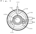
FIG. 7 is a partial block diagram showing the same
fuel vaporizing apparatus and a catalyst combustion
apparatus using the same; and
FIG. 8 is an essential sectional block diagram showing
a fuel vaporizing apparatus according to another
embodiment of the present invention and a catalyst
combustion apparatus using the same.
DESCRIPTION OF THE SYMBOLS
- 1
- Fuel tank
- 2
- Fuel feed pump
- 3
- Fuel feed course
- 4
- Fuel jet port
- 5
- Air feed fan
- 6
- Air feed course
- 7
- Air jet port
- 8
- Vaporizing unit
- 9
- Vaporizing unit heater
- 10
- Catalyst heating unit
- 11
- Combustion chamber
- 12
- Catalyst combustion unit
- 13
- Catalyst heater
- 14
- Combustion gas exhaust port
- 15
- Mixture space
- 16
- Catalyst heating unit conductive holes
- 17
- Vaporizing unit through-hole
- 18
- Diverting air port
- 19
- Current plate
- 101
- Fuel feed course
- 102
- Fuel jet port
- 103
- Vaporizing surface
- 104
- Heater
- 105
- Air feed course
- 106
- Case
- 107
- Mixture space
- 108
- Air diverting port
- 109
- Catalyst combustion unit
- 110
- High-emissivity film
- 111
- Radiation heat receptor
- 112
- Vaporizing unit opening
- 113
- Mixture circulation port
- 114
- Current plate
- 115
- Liquid fuel diverting unit
- 120
- Fuel vaporizing apparatus
- 121
- Catalyst combustion apparatus
BEST MODE FOR CARRYING OUT THE INVENTION
Hereinafter, with reference to the drawings, the
description will be made of embodiments of the present
invention.
In order to carry out the present invention, in
addition to a catalyst body having a multiplicity of
conductive holes and oxidative activity to various fuel,
and a vaporizing unit for liquid fuel, an ignition device
and a flow rate control device, or, as required, a
temperature detection device, a driving unit or the like
are required. As the catalyst body, a honeycomb carrier
for metal or ceramics, or a plaiting body of ceramic fiber,
a porous sintered body or the like carrying an active
constituent mainly composed of noble metal such as platinum
and palladium can be used. Also, as air-introduction
porous body, there can be used honeycomb structure of
ceramics, or a plaiting body of ceramic fiber, porous
sintered body or the like. Further, in order to control
air flow rate, a manual needle valve or a motor-driven
solenoid valve or the like are used, and in order to control
flow rate of liquid fuel, an electromagnetic pump or the
like is used. For the other driving portions, manual lever
operation, automatically-controlled motor driving or the
like can be used. As an ignition device, an electric heater,
a discharging igniter or the like can be used. In this
respect, they have all been means widely used
conventionally, and any other known means can be used.
(First Embodiment)
FIG. 1 is a partial sectional block diagram showing
a catalyst combustion apparatus according to an embodiment
of the present invention.
In FIG. 1, reference numeral 1 denotes a fuel tank;
2, a fuel feed pump; 3, a fuel feed course; 4, a fuel jet
port; 5, an air feed fan; 6; an air feed course; 7, an
air jet port: 8, a vaporizing unit, whose inner side is
coated with black heat-resisting paint; 9, a vaporizing
unit heater; and 10, a catalyst heating unit obtained by
causing metallic base material to carry noble metal of
platinum group, which is provided so as to come into contact
with the vaporizing unit 8.
Further, reference numeral 11 denotes a combustion
chamber; 12, a catalyst combustion unit obtained by causing
a ceramic honeycomb having a multiplicity of conductive
holes to carry noble metal of platinum group; 13, a catalyst
heater; and 11, a combustion gas discharge port.
Next, with reference to FIG. 1, the description will
be made of an operation and characteristics of the present
embodiment. Liquid fuel (kerosene is used here) within
the fuel tank 1 is jetted into the air feed course 6 from
the fuel jet port 4 by way of the fuel feed course 3 after
its flow rate is controlled at the fuel feed pump 2.
Also, air is fed by the air feed fan 1, to which voltage
is applied so as to provide an adequate air flow rate,
and is jetted into the vaporizing unit 8 from the air jet
port 7 after mixed with liquid fuel by way of the air feed
course 6.
Further, premixed mixture to be jetted from the air
jet port 7 collides against a wall, which is opposed thereto,
in the vaporizing unit 8, which is controlled to exceed
250°C under the ON-OFF control of the vaporizing unit heater
9, and the liquid fuel is vaporized there.
Also, the greater part of the premixed mixture
consisting of the liquid fuel thus vaporized and air is
directly fed to the catalyst combustion unit 12.
In this case, an amount of feed is adjusted by the
fuel feed pump 2 correspondingly to the amount of combustion,
whereby the gas on the upstream surface in the catalyst
combustion unit 12 has excellent combustion exhaust gas
characteristics and its temperature is controlled to
exceed 500°C, at which the combustion is allowed to be
continued, and not to exceed 900°C, which is a heat limit.
At this time, an amount of heat equal to 50 to 60%
of an calorific value of the liquid fuel to be fed is emitted
on the upstream side of the catalyst combustion unit 12.
Also, a part of the premixed mixture comes into contact
with the catalyst heating unit 10, which has been arranged
in contact with the vaporizing unit 8, to perform a catalyst
reaction (however, contact frequency of the premixed
mixture with the catalyst heating unit 10 varies with the
amount of combustion). At this time, because of heat to
be generated by this catalyst reaction, and radiation heat
to be flowed back from the catalyst combustion unit 12,
the catalyst heating unit 10 is maintained at temperatures
of 400 to about 600°C, at which lowered catalyst activity
is not noticeably affected.
Further, a part of heat of reaction generated at the
catalyst heating unit 10 is transmitted to the vaporizing
unit 8 arranged in contact by conduction of heat. Also,
a part of radiation heat of the catalyst heating unit 12
on the upstream side is directly flowed back to the
vaporizing unit 8 by way of an opening of the catalyst
heating unit 10.
Further, in the vaporizing unit 8, heat of conduction
from the catalyst heating unit 10, and radiation heat from
the catalyst combustion unit 12 are utilized together with
heat of vaporization from the liquid fuel for preheating
of the premixed mixture, and therefore, a part of these
heat is flowed back to the catalyst combustion unit 12
again.
As described above, due to flow-back effect of heat
of reaction in the catalyst heating unit 10 and the catalyst
combustion unit 12 to the vaporizing unit 8, power
consumption of the vaporizing unit heater 9 required to
control the vaporizing unit 8 to exceed 250°C can be greatly
reduced, and due to preheating effect of the premixed
mixture, it becomes possible to reduce the fuel consumption,
that is, to realize high heat utilization efficiency.
Therefore, it is possible to provide a catalyst combustion
apparatus having high heat utilization efficiency,
excellent in energy-saving property and cost
effectiveness.
(Second Embodiment)
The description will be made of a second embodiment
according to the present invention. The present
embodiment is the same in basic configuration as the first
embodiment, but is different in that between the vaporizing
unit 8 and the catalyst combustion unit 12, there is
provided restriction means 210 of restraining the flow
of mixture to the catalyst combustion unit 12. Accordingly,
the description will be mainly made of this point of
difference.
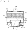
FIG. 2 is an essential sectional view showing the
present embodiment. In FIG. 2, a reference numeral 15
denotes a space portion of mixture, provided between a
vaporizing unit 8 and a catalyst heating unit 10, which
is space in which the mixture circulates. Also, a
reference numeral 16 denotes conductive holes provided
in the catalyst heating unit 10. The catalyst heating
unit 10 is box-shaped, and is arranged to couple to the
vaporizing unit 8 in terms of conduction of heat so as
to cover it. On the base portion and the side portions
of the catalyst heating unit 10, catalyst heating unit
conductive holes 16 are provided, through which the mixture
flows out of the catalyst heating unit 10. Such a catalyst
heating unit 10 constitutes the full or partial restriction
means 210 according to the present invention.
In this respect, the box-shape written in the present
specification includes a cylindrical shape, to say nothing
of a rectangular parallelepiped shape and widely includes
not only 90 degrees in shape of the angle portion, but
also any round shapes.
Next, with reference to FIG. 2, the description will
be made of an operation and characteristics of the present
embodiment.
In the same way as the first embodiment, premixed
mixture to be jetted from the air jet port 7 collides against
a wall, which is opposed thereto, in the vaporizing unit
8, which is controlled to exceed 250°C under the ON-OFF
control of the vaporizing unit heater 9, and the liquid
fuel is vaporized here.
The premixed mixture consisting of the liquid fuel
thus vaporized and air passes through mixture space 15,
and thereafter, comes into contact with the catalyst
heating unit 10 for reaction, which has been arranged in
contact with the vaporizing unit 8, and is fed to the
catalyst combustion unit 12 by way of catalyst heating
unit conductive holes 16.
At this time, heat generated by this catalyst reaction
and radiation heat to be flowed back from the catalyst
combustion unit 12 maintain the catalyst heating unit 10
at temperatures of 600 to 800°C.
Further, a part of heat of reaction to be generated
in the catalyst heating unit 10 is transmitted to the
vaporizing unit 8 due to conduction of heat from a portion
installed in contact and heat radiation from a surface
opposite to the vaporizing unit 8.
Also, in the vaporizing unit 8, heat of conduction
and radiation heat from the catalyst heating unit 10 are
also utilized for preheating of premixed mixture together
with heat of vaporization of liquid fuel, and therefore,
a part of these heat is flowed back to the catalyst
combustion unit 12 by way of the catalyst heating unit
10 again.
As described above, due to flow-back effect of heat
of reaction in the catalyst heating unit 10 and the catalyst
combustion unit 12 to the vaporizing unit 8, the power
consumption of the vaporizing unit heater 9 required to
control the vaporizing unit 8 to exceed 250°C can be greatly
reduced, and due to preheating effect of the premixed
mixture, it becomes possible to reduce the fuel consumption,
that is, to realize high heat utilization efficiency.
Also, since the catalyst heating unit 10 is box-shaped,
there is an advantage that the mixture is sufficiently
fed to the catalyst heating unit 10, and the reaction of
the catalyst heating unit 10 occurs more actively.
Also, since the catalyst heating unit 10 is box-shaped,
there is an advantage that the mixture is sufficiently
mixed within, and is discharged toward outside.
Therefore, it is possible to provide a catalyst
combustion apparatus having high heat utilization
efficiency, excellent in energy-saving property and cost
effectiveness.
Further, since the greater part of heat recovery from
the catalyst heating unit 10 to the vaporizing unit 8 is
performed as described above, even when the catalyst
combustion unit 12 is not provided downstream, that is,
it is also applicable to a flame combustion apparatus,
and a widely applicable vaporizing apparatus can be
provided.
In this respect, in the present embodiment, the
catalyst heating unit 10 has entirely been made of metallic
base material, but the neighborhood of the catalyst heating
unit conductive holes 16 may be replaced with a ceramic
honeycomb having a multiplicity of conductive holes
carrying noble metal of platinum group, and the same effect
as described above can be obtained. In the case where
lower catalytic activity when used for a long term is taken
into consideration, a better tendency can be obtained.
(Third Embodiment)
The description will be made of a third embodiment
according to the present invention. The present
embodiment is the same in basic configuration as the second
embodiment, but is different in that an air jet port at
the tip end of the air feed course is caused to penetrate
the vaporizing unit in order to prevent air to be fed from
the air feed course from coming into contact with the
vaporizing unit for being heated as far as possible, and
that part of the fuel feed course is provided within the
vaporizing unit. Accordingly, the description will be
mainly made of these points of difference.
FIG. 3 is an essential sectional view showing the
present embodiment.
In FIG. 3, a reference numeral 17 denotes a vaporizing
unit through-hole, and an air jet port 7 at the tip end
of the air feed course 6 is caused to penetrate the
vaporizing unit.
Liquid fuel within the fuel tank 1 passes through the
fuel feed course 3 embedded and provided within the
vaporizing unit 8 after the flow rate of the liquid fuel
is controlled at the fuel feed pump 2.
In the fuel feed course 3, the liquid fuel is controlled
to exceed 250°C under the ON-OFF control of the vaporizing
unit heater 9, and therefore, the liquid fuel is vaporized
while passing through the interior of the vaporizing unit
8, and thereafter, is jetted from a fuel jet port 4 into
the air feed course 6.
Since the periphery of a portion where the fuel feed
course 3 has been arranged within the vaporizing unit 8
is covered with a vaporizing unit heater 9, there is also
provided an insulation effect for restraining radiation
of heat from the vaporizing unit 8.
Also, air is fed by the air feed fan 1, to which voltage
is applied so as to provide an adequate air flow rate,
and is jetted into mixture space 15 from the air jet port
7 after mixed with fuel gas by way of the air feed course
6.
Also, since the air jet port 7 at the tip end of the
air feed course 6 is set up so as to penetrate the vaporizing
unit 8, premixed mixture of vaporized liquid fuel and air
flows into air mixture space 15 without coming into direct
contact with the vaporizing unit 8, and after passing
through the space 15, comes into contact with a catalyst
heating unit 10 arranged in contact with the vaporizing
unit 8 for reaction, and is fed to a catalyst combustion
unit 12 by way of catalyst heating unit through-holes 16.
In this respect, although it is written that the air jet
port 7 is caused to penetrate the vaporizing unit 8, in
the present embodiment, strictly speaking, the air jet
port 7 is in contact with part of the vaporizing unit 8.
However, since the jet direction of air is set to right
above, it can be said that it is hardly affected by the
heating in the vaporizing unit 8, and that the air jet
port 7 completely penetrates the vaporizing unit 8 really.
At this time, heat generated by this catalyst reaction
and radiation heat to be flowed back from the catalyst
combustion unit 12 maintain the catalyst heating unit 10
at temperatures of 600 to 800°C.
Further, part of heat of reaction to be generated in
the catalyst heating unit 10 is transmitted to the
vaporizing unit 8 due to conduction of heat from a portion
installed in contact and heat radiation from a surface
opposite to the vaporizing unit 8.
Also, in the vaporizing unit 8, heat of conduction
and radiation heat from the catalyst heating unit 10 are
only utilized to vaporize the liquid fuel, and therefore,
the amount of heat to be fed to the vaporizing unit 8 can
be reduced to one eighth to one sixth when vaporized as
premixed mixture.
As described above, the power consumption of the
vaporizing unit heater 9 required to control the vaporizing
unit 8 to exceed 250°C can be reduced to substantially
zero, and spontaneous combustion can be implemented.
Therefore, it is possible to provide a catalyst
combustion apparatus excellent in cost effectiveness with
low running cost.
Further, since the greater part of heat recovery from
the catalyst heating unit 10 to the vaporizing unit 8 is
performed as described above, even when the catalyst
combustion unit 12 is not provided downstream, that is,
it is also applicable to a flame combustion apparatus,
and a widely applicable vaporizing apparatus can be
provided.
In this respect, in the prevent embodiment, the liquid
fuel vaporized is once jetted into the air feed course
6 from the fuel jet port 4, but it may be possible to mix
with air after directly jetted into the mixture space 15,
and the same effect as described above can be obtained.
(Fourth Embodiment)
The description will be made of a fourth embodiment
according to the present invention. The present
embodiment is the same in basic configuration as the third
embodiment, but is different in that a diverting air port
18 is provided at a downstream position of the air jet
port 7 of the catalyst heating unit 10 in such a manner
that part of air does not come into contact with the catalyst
heating unit 10, that a current plate 19 for promoting
mixture of diverted air and mixture is provided at a
position close to the catalyst combustion unit 12
downstream of the diverting air port 18 in the state of
contacting with the heater 13, and that there is provided
a fuel jet port 4 at the tip end of the fuel feed course
3 so that liquid fuel provided from the fuel feed course
3 collide with the vaporizing unit 8.
Accordingly, the description will be mainly made of
these points of difference.
FIG. 4 is an essential sectional view showing the
present embodiment. In FIG. 4, an opening provided at
the center of the catalyst heating unit 10 is an diverting
air port 18, through which diverted air passes.
A current plate 19 is arranged downstream of the
diverting air port 18, and this current plate 19 is arranged
in contact with a heater 13 for heating the catalyst
combustion unit 12. The current plate 19 is configured
by causing metallic base material to carry noble metal
of platinum group.
Next, with reference to FIG. 4, the description will
be made of an operation and characteristics of the present
embodiment.
Liquid fuel within the fuel tank 1 is jetted into the
mixture space 15 from the fuel jet port 4 by way of the
fuel feed course 3 after its flow rate is controlled at
the fuel feed pump 2.
Further, liquid fuel to be jetted from the fuel jet
port 4 collides against a wall, which is opposed thereto,
in the vaporizing unit 8, which is controlled to exceed
250°C under the ON-OFF control of the vaporizing unit heater
9, and within the vaporizing unit 8, the liquid fuel is
vaporized.
Also, air is fed by the air feed fan 1, to which voltage
is applied so as to provide an adequate air flow rate,
and is jetted into the mixture space 15 from the air jet
port 7 by way of the air feed course 6, but the air jet
port 7 at the tip end of the air feed course 6 is provided
to penetrate the vaporizing unit 8. Therefore, the air
flows straight toward the catalyst combustion unit 12
without coming into direct contact with the vaporizing
unit 8, and part of the air is fed to outside of the diverting
air port 18, directly into the combustion chamber 11 without
mixing with the liquid fuel vaporized.
The air which did not flow out at the diverting air
port 18 is mixed with the liquid fuel which has collided
with the wall, to which the vaporizing unit 8 is opposed,
and has been vaporized, within the mixture space 15, and
thereafter, comes into contact with the catalyst heating
unit 10 arranged so as to contact the vaporizing unit 8
for reaction (however, condition of insufficient air for
the adequate air flow rate) and passes through the catalyst
heating unit conductive holes 16.
On the other hand, the air which has passed through
the diverting air port 18 forms a flow toward a flow of
the premixed mixture to be formed in the circumference
of the center of the combustion chamber 11 because of
collision with a current plate 19, and after mixed with
the premixed mixture, is fed to the catalyst combustion
unit 12.
At this time, due to heat to be generated by this
catalyst reaction, and radiation heat to be flowed back
from the catalyst combustion unit 12, a condition that
air is insufficient for the adequate air flow rate is met,
and therefore, the temperature of the catalyst heating
unit 10 is lower than that of the third embodiment, and
is maintained at temperatures of 500 to 700°C, at which
lowered catalyst activity is not noticeably affected.
Further, since the current plate 19 is provided in
the vicinity of the catalyst combustion unit 12 although
it comes into contact with diverted air at as low
temperatures as about 50°C, it becomes possible to restrain
tar from adhering thereto.
Even when tar adheres, by the passage of electric
current through the catalyst combustion unit heater 13
before commencement of catalyst combustion, the current
plate 19 also rises in temperature, and decomposition
reaction of tar is performed on the surface of catalyst
carried on the current plate 19. Therefore, there is no
possibility that problems such as malodor due to
accumulation of tar is raised.
Further, since the catalyst combustion unit 12 has
excellent combustion exhaust gas characteristics, the same
degree of mixture characteristics as when premixed mixture
is fed can be realized with the provision of the current
plate 19.
Further, part of heat of reaction to be generated in
the catalyst heating unit 10 is transmitted to the
vaporizing unit 8 due to conduction of heat from a portion
installed in contact and heat radiation from a surface
opposite to the vaporizing unit 8.
Also, in the vaporizing unit 8, heat of conduction
and radiation heat from the catalyst heating unit 10 are
only utilized to vaporize the liquid fuel, and therefore,
the amount of heat to be fed to the vaporizing unit 8 can
be reduced to one eighth to one sixth when it is vaporized
as premixed mixture.
In addition, air is diverted and flow rate of the
premixed mixture, which comes into contact with the
catalyst heating unit 10, is reduced, whereby an amount
of heat recovery from the catalyst heating unit 10 to the
premixed mixture is reduced, and therefore, the power
consumption of the vaporizing unit heater 9 required to
control the vaporizing unit 8 to exceed 250°C can be reduced
to zero over all the combustion amount areas as described
above, and spontaneous combustion can be realized.
Therefore, it is possible to provide a catalyst
combustion apparatus excellent in cost effectiveness with
low running cost.
Further, since the greater part of heat recovery from
the catalyst heating unit 10 to the vaporizing unit 8 is
performed as described above, even when the catalyst
combustion unit 12 is not provided downstream, that is,
it is also applicable to a flame combustion apparatus,
and a widely applicable vaporizing apparatus can be
provided.
In this respect, in the present embodiment, the current
plate 19 is provided so as to contact the catalyst
combustion unit heater 13, but it may be possible to isolate
for setting up, and if the current plate 19 is arranged
in the vicinity of the catalyst combustion unit 12, the
same effect as described above can be obtained.
Also, air diverted from the diverting air port 18
opened in the catalyst heating unit 10 has been circulated,
but it may be possible to feed air into the combustion
chamber 11 after the air is diverted upstream of the
vaporizing unit 8 in advance (See 6 in FIG. 4), and the
same effect as described above can be obtained although
the configuration of the combustion apparatus becomes
slightly complicated.
Further, as ignition means, there has been used a heat
rising system from upstream of a catalyst combustion unit
using the catalyst combustion unit heater 12, but when
a piezo-electric igniter is used as an igniter to be used
when catalyst combustion is started by flame combustion,
a catalyst combustion apparatus without power supply can
be realized.
In the foregoing, the description has been made of
an example in which the present invention is applied to
a catalyst combustion apparatus using liquid fuel, but
the present invention is not limited thereto as a matter
of course. In other words, the following cases are also
included in the present invention.
For the carrier of the catalyst combustion unit,
ceramic honeycomb is used, but as long as it has a
multiplicity of conductive holes in which premixed mixture
can be circulated, it is not limited to its material and
shape, but a sintered body of, for example, ceramics and
metal, metallic honeycomb and metallic nonwoven material,
a plaiting body of ceramic fiber or the like can be utilized,
the shape is also not limited to a flat plate, but a curved
shape, a cartridge shape or a corrugated panel shape or
the like can be arbitrarily set in accordance with
processability and applications of the material.
As active constituent, there are generally noble metal
of platinum group such as platinum, palladium, and rhodium,
and their mixing body, other metals and their oxide, and
their mixing composition may be used, and the active
constituent responsive for type of fuel and conditions
for use can be selected.
On the outer peripheral wall of the combustion chamber,
there may be provided a heat ray permeating window made
of crystallization glass, quartz glass, or the like,
through which heat ray is permeated, or in place of the
heat ray permeating window, a secondary radiator
configured by material with excellent thermal conductivity
having high surface emissivity, a radiation heat receptor,
or the like added with heating medium passage made of copper
pipe or the like may be provided, and in either case, the
same effect as described above can be obtained.
Further, as ignition means, there has been used a heat
rising system from the upper stream of the catalyst
combustion unit using an electric heater, but as an igniter
for starting flame combustion, the use of a piezo-electric
igniter is effective means for completing the equipment
without power supply.
Next, with reference to the drawings, the description
will be made of embodiments of the present invention.
(Fifth Embodiment)
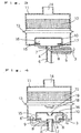
FIG. 5 is an essential sectional block diagram showing
a fuel vaporizing apparatus according to an embodiment
of the present invention and a catalyst combustion
apparatus using the same. A reference numeral 101 denotes
a fuel feed course; 102, a fuel jet port; 103, a vaporizing
surface of a vaporizing unit 103'; 104, a heater; and 105,
an air feed course, the tip end of which is caused to
penetrate part of the vaporizing surface 103. The
vaporizing unit 103' has a box shape, and the under surface
thereof is mounted with a heater 104.
A reference numeral 107 denotes mixture space as an
example of first mixture space; 107', second mixture space;
108, an air diverting port; and 109, a catalyst combustion
unit, which is arranged downstream of the mixture space
107, carrying platinum group catalytic component in the
ceramic honeycomb. A reference numeral 110 denotes
high-emissivity film, which covers the surface of a case
106 forming the mixture space 107 on the catalyst combustion
unit 109 side. The first mixture space 107 is formed by
a box-shaped case 106, and is arranged to cover the
vaporizing unit 103'. Further, the case 106 is coupled
to the vaporizing unit 103' in terms of conduction of heat.
Further, in the base portion (exists above in the
figure) of the case 106 for forming the mixture space 107,
there is formed an air diverting port 108. An edge 60
of the air diverting port 108 protrudes toward the interior
of the mixture space 107.
The tip end of the fuel feed course 101 is oriented
toward the vaporizing surface 103 of the vaporizing unit
103' so that the liquid fuel collides with the vaporizing
surface 103. Further, the air feed course 105 is arranged
such that the air can be jetted toward the center of the
base portion of the case 106. As described above, there
is opened the air diverting port 108 at the center of the
base portion.
The fuel vaporizing apparatus 120 is configured by
the fuel feed course 101, the fuel jet port 102, the
vaporizing surface 103, the air feed course 105, the first
mixture space 107, the second mixture space 107' and the
air diverting port 108, and the fuel vaporizing apparatus
120 is combined with the catalyst combustion unit 109 to
constitute a catalyst combustion apparatus 121. The
heater 104 is used when the temperature on the vaporizing
surface 103 is so insufficient that vaporization cannot
be sufficiently performed such as during rising.
Next, the description will be made of an operation
of the present embodiment.
Liquid fuel (kerosene is used here) to be fed is jetted
toward the vaporizing surface 103 through the fuel jet
port 102 at the tip end by way of the fuel feed course
101. In this case, during starting and when insufficient
in amount of heat, the temperature of the vaporizing surface
103 is controlled to maintain the temperature of
vaporization of the fuel or higher (250°C or higher in
kerosene) under the ON-OFF control of the heater 104
provided, and the liquid fuel is vaporized here. Of course,
even if no electric power is given to the heater 104,
vaporization will be performed if the temperature on the
vaporizing surface 103 is high.
Air for combustion to be fed by way of the air feed
course 105, whose tip end is caused to penetrate the
vaporizing surface 103, flows straight upward, and the
greater part thereof is discharged out of the air diverting
port 108, and part flows into the mixture space 107.
This part of air diverted is circulated on the
vaporizing surface 103 and within the mixture space 107,
is mixed with the liquid fuel vaporized on the vaporizing
surface 103 here, further is mixed while mounting on a
flow of air to be fed from the air feed course 105, and
thereafter, is discharged out of the mixture space 107
by way of the air diverting port 108.
With such a configuration, part of air to be fed from
the air feed course 105 is discharged out of the mixture
space 107 without coming into contact with the vaporizing
unit 103' as it is, that is, without being heated by means
of heat for heating the vaporizing unit 103', and remaining
air is mixed with fuel vaporized while flowing within the
mixture space 107 to leave the mixture space 107 in the
course of time.
Thereby, it becomes possible to realize excellent
mixture characteristics, and the flow rate of air which
circulates within the mixture space 107 to come into contact
with the vaporizing surface 103 becomes smaller than when
there is no air directly leaving the mixture space 107
from the air feed course 105. As a result, during
vaporization, air is not heated wastefully, but its heating
energy is effectively used for vaporizing the liquid fuel,
and there is provided an effect that the amount of heat
required to vaporize can be greatly reduced.
The mixture discharged out of the air diverting port
108 is further mixed in the second mixture space 107',
and is fed to a catalyst combustion unit 109 provided
downstream thereof, in which oxidation reaction is
performed.
Due to this heat of reaction, the temperature on the
surface of the upper stream of the catalyst combustion
unit 109 is maintained at 500°C or to exceed 500°C capable
of continuing the combustion and at 900°C, which is
temperature limit at which durability is taken into
consideration, or lower.
At this time, an amount of heat corresponding to 50
to 60% of calorific value of the liquid fuel to be fed
by means of catalyst combustion on the catalyst combustion
unit 109 is radiated on the upstream side of the catalyst
combustion unit 109.
Since the case 106 of the first mixture space 107 is
covered with the high-emissivity film 110, of radiation
heat for reaching from the catalyst combustion unit 109,
90% or higher radiates secondary heat from the surface
opposing to the vaporizing surface 103 of the case 106
after absorbed by the high-emissivity film 110. Further,
the heat of the case 106 is transmitted to the vaporizing
surface 103 of the vaporizing unit 103' from a portion
contiguous to the case 106 by conduction of heat to be
used for vaporizing the liquid fuel.
As a result, the fuel is vaporized through heat of
combustion from the catalyst combustion unit 109 and there
is obtained the effect that the electric power for the
heater 109 will be hardly needed. Further, since the
radiation heat from the catalyst combustion unit 109 is
utilized for preheating the premixed mixture together with
vaporization of the liquid fuel, part of these is flowed
back to the catalyst combustion unit 109 again, and there
is obtained the effect that the energy will not be used
wastefully.
In the foregoing, it has been shown that it is possible
to provide a catalyst combustion apparatus having high
heat utilization efficiency, excellent in energy-saving
property and cost effectiveness.
In this respect, in the present embodiment, the surface
of the case 106 on the catalyst combustion unit 109 side
has been covered with the high-emissivity film 110, but
it may be possible to configure the case 106 itself by
base material with high-emissivity.
Also, when the case 106 is configured by base material
having high thermal conductivity such as copper and
aluminum, or when integrally configured with the
vaporizing surface 103 so as to restrain the contact thermal
resistance, it becomes possible to more effectively
transmit radiation heat from the surface of the upper stream
of the catalyst combustion unit 109 to the vaporizing
surface 103, and further the effect equal to or better
than the above-described one can be expected.
The present invention may also be applied to such a
configuration that the air feed course 105 is diverged
on the upstream side and one 105' of them is caused not
to pass through the first mixture space 107 at all as shown
in the figure, but is directly conducted to the second
mixture space 107'.
(Sixth Embodiment)
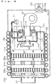
FIG. 6 is an essential sectional block diagram showing
a fuel vaporizing apparatus according to another
embodiment of the present invention and a catalyst
combustion apparatus using the same, and FIG. 7 is a partial
block diagram showing the same apparatus.
The present embodiment is the same in basic
configuration as the fuel vaporizing apparatus of (the
fifth embodiment) and the catalyst combustion apparatus
using the same, but is different in that a case 106 is
formed with mixture circulation ports 113 for discharging
the mixture out, which is circulated within the mixture
space 107, that a current plate 100 is provided downstream
of an air diverting port 108, that a vaporizing surface
103 is provided in a substantially vertical direction and
the low end thereof is set to a lower position than the
fuel jet port 102, that a liquid fuel diverting unit 115
is provided at a lower position than a fuel jet port 102,
and that a heater 104 is provided along the back surface
of the vaporizing surface 103. Accordingly, the
description will be mainly made of these points of
difference.
A fuel vaporizing apparatus 120 is configured by a
fuel feed course 101; the fuel jet port 102; the vaporizing
surface 103; an air feed course 105; the case 106; a first
mixture space 107; a second mixture space; and the air
diverting port 108, and the fuel vaporizing apparatus 120
is combined with the catalyst combustion unit 109 to
constitute a catalyst combustion apparatus 121. The
heater 104 is used when the temperature on the vaporizing
surface 103 is so insufficient that vaporization cannot
be sufficiently performed such as during rising.
Liquid fuel to be fed is jetted to the vaporizing
surface 103 from the fuel jet port 102 at the tip end by
way of the fuel feed course 101 from the fuel pump 21.
In this case, during starting and when insufficient in
amount of heat, the vaporizing surface 103 is controlled
to maintain the temperature of vaporization of the fuel
or higher (250°C or higher in kerosene) by the heater 104
provided.
Of course, even if no electric power is given to the
heater 104, vaporization will be performed if the
temperature on the vaporizing surface 103 is high. If
small in amount of combustion, the whole quantity of the
liquid fuel will be vaporized in a moment after collides
with the vaporizing surface 103.
If large in amount of combustion, the liquid fuel will
not be vaporized in the whole quantity in a moment after
the collision, but, as shown in FIG. 7, part of the fuel
in a liquid state will flow down along the vaporizing
surface 103 to collide with the liquid fuel diverting unit
115 projectingly provided on the vaporizing surface 103.
Since the liquid fuel diverting unit 115 is
projectingly arranged, the liquid fuel is dispersed
immediately. When dispersed, the area, in which the liquid
fuel comes into contact with the vaporizing surface 103,
is increased to be prone to obtain heat.
As described above, the liquid fuel obtains heat from
the vaporizing surface 103 to vaporize the fuel in the
liquid state.
With such a configuration as to disperse the liquid
fuel along the vaporizing surface 103 for vaporization,
it becomes possible to uniformly heat the liquid fuel for
vaporization, and part of the fuel can be prevented from
re-condensing.
The heater 104 is arranged along the vaporizing surface
103. With this configuration to arrange the heater 104
along the vaporizing surface 103, heat generated by the
heater 104 is effectively utilized as heat of vaporization
of the liquid fuel, and power consumption in the heater
104 can be reduced.
Air for combustion to be fed from a blower fan 22 by
way of the air feed course 105, whose tip end is caused
to penetrate the vaporizing surface 103, is diverted by
a diverting port 108, part of air circulates within a first
mixture space 107, and after mixed with the fuel vaporized
on the vaporizing surface 103, passes through the mixture
circulation port 113 provided in the case 106 to be
discharged out of the mixture space 107.
Also, the greater part of the remaining air is directly
discharged out of the mixture space 107 by way of the air
diverting port 108 without coming into direct contact with
the vaporizing surface 103.
Further, the air which has directly been discharged
out of the mixture space 107 by way of the air diverting
port 108 collides with the current plate 114 provided
downstream of the air diverting port 108, thereafter is
dispersed, and forms a flow for circulating around the
air diverting port 108 and going toward the mixture
discharged out of the mixture circulating port 113, and
then is mixed with the mixture. Therefore, since the
temperature drop is low within the mixture space 107, the
liquid fuel vaporized does not re-condense.
With such a configuration as to divert air through
the use of the diverting port 108, and to directly discharge
a part of air out of the mixture space 107 to reduce a
flow rate to be brought into contact with the vaporizing
surface 103 as described above, it becomes possible to
greatly reduce the amount of heat required for
vaporization.
Therefore, it is possible to provide a fuel vaporizing
apparatus 120 excellent in cost effectiveness with low
running cost.
Further, with the configuration to cause the air thus
diverted to collide with the current plate 114 for mixing,
it is possible to feed uniform mixture, and therefore,
it is also possible to install any combustion unit such
as flame combustion and catalyst combustion on the
downstream side, and to provide a widely applicable fuel
vaporizing apparatus 120.
Mixture uniformly premixed burns by catalysis in the
catalyst combustion unit 109 to emit radiation heat. The
heat is conducted to a heat-receiving tube 25 by way of
heat-receiving fins 26a and a combustion barrel 26, and
is recovered by a medium flowing therein.
Also, a part of the radiation heat is effectively
absorbed by the case 106 made of high-emissivity material,
conducts to the vaporizing surface 103 and is utilized
for vaporization of the fuel. Further, from combustion
gas to be discharged from the catalyst combustion unit
109, the heat is recovered by the heat-receiving fins 26a
before emitted from an exhaust flue 27, and is recovered
by the medium by way of the heat-receiving tube 25.
The medium is circulated by the operation of a pump
24, and when it is carried to an external radiator 23,
the medium gives off the heat here and it is utilized as
a heat source outside.
A fuel vaporizing apparatus and a catalyst combustion
apparatus using the same are configured as described above,
whereby it is possible to provide a fuel vaporizing
apparatus and a catalyst combustion apparatus which reduce
electric power required to vaporize the fuel and do not
re-condense.
In this respect, in the present embodiment, the place
for diverting air for combustion has been provided on the
downstream side of the vaporizing surface 103, but it may
be possible to provide it on the upstream side of the
vaporizing surface 103, and to feed air for combustion
after diverting in advance. Although the configuration
of the fuel vaporizing apparatus 120 becomes slightly
complicated, the same effect as described above can be
obtained (See 105' of FIG. 5).
(Seventh Embodiment)
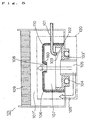
FIG. 8 is an essential sectional view showing a
catalyst combustion apparatus according to another
embodiment of the present invention. The present
embodiment is the same in basic configuration as the fuel
vaporizing apparatus of (the fifth embodiment) and the
catalyst combustion apparatus using the same, but is
different in that the vaporizing surface 103 and a radiation
heat receptor 111 are integrally configured, that the
catalyst combustion unit 109 is arranged to oppose to the
radiation heat receptor 111, that the radiation heat
receptor 111 is covered with high-emissivity material 10,
that the vaporizing surface 103 is protruded from the
radiation heat receptor 111 on the catalyst combustion
unit 109 side, and that the back surface of the vaporizing
surface 103 is covered with high-emissivity material 10.
The description will be mainly made of these points of
difference.
The fuel vaporizing apparatus 120 is configured by
a fuel feed course 101, a fuel jet port 102, a vaporizing
surface 103 of a box-shaped vaporizing unit 103' and an
air feed course 105, and the fuel vaporizing apparatus
120 is combined with the catalyst combustion unit 109 to
constitute a catalyst combustion apparatus 121, and
high-emissivity film 110 is further provided in order to
provide at least the back surface of the vaporizing surface
103, which is the surface on the catalyst combustion unit
109 side, with high emissivity. This is used in order
to improve the performance of the fuel vaporizing apparatus
120. The heater 104 is used when the temperature of the
vaporizing surface 103 is insufficient. The vaporizing
unit 103' is box-shaped, and its base portion forms the
vaporizing surface 103, and its side surface 3a is formed
with a vaporizing unit opening 112.
Also, the fuel feed course 101 and the air feed course
105 are both adapted to blow off the fuel or air horizontally
respectively, for causing it to collide with the vaporizing
surface 103.
The radiation heat receptor 111 is integrally
configured with the vaporizing surface 103 in terms of
conduction of heat, and the catalyst combustion unit 109
is arranged downstream of the radiation heat receptor 111.
In other words, the plate-shaped radiation heat receptor
111 is in an opposed state to the catalyst combustion unit
109, and further at the center of the radiation heat
receptor 111, the box-shaped vaporizing unit 103' is
arranged, and protrudes on the catalyst combustion unit
109 side.
Liquid fuel to be fed is jetted onto the vaporizing
surface 103 through the fuel jet port 102 at the tip end
by way of the fuel feed course 101. Air for combustion
is also jetted onto the vaporizing surface 103 by way of
the air feed course 105 arranged around the fuel feed course
101. The vaporizing surface 103 is vertical.
In this case, the vaporizing surface 103 is controlled
to exceed the temperature of vaporization of the fuel (250°C
or higher in kerosene), the liquid fuel is vaporized after
it collides with the vaporizing surface 103, the fuel vapour
vaporized is dispersed to form a flow on the air side to
be circulated over this periphery, and is mixed with air
into mixture.
Liquid fuel, which could not be vaporized on the
vaporizing surface 103 at this time, also flows down along
the vaporizing surface 103 because the vaporizing surface
103 is vertical, and is accumulated on the underside of
a member 3a for joining the vaporizing surface 103 to the
radiation heat receptor 111, where heat is obtained to
vaporize.
This mixture is fed to the catalyst combustion unit
109 provided downstream by way of the vaporizing unit
opening 112, and oxidation reaction is performed here.
Due to this heat of reaction, the temperature on the surface
of the upper stream of the catalyst combustion unit 109
is maintained to exceed 500°C capable of continuing the
combustion and at 900°C, which is temperature limit at
which durability is taken into consideration, or lower.
At this time, an amount of heat corresponding to 50
to 60% of calorific value of the liquid fuel to be fed
is radiated on the upstream side of the catalyst combustion
unit 109. Since the radiation heat receptor 111 is
integrally configured with the vaporizing surface 103 and
the catalyst combustion unit 109 is arranged downstream
of the radiation heat receptor 111, the back surface of
the vaporizing surface 103 and the radiation heat receptor
111 are opposed to the catalyst combustion unit 109, and
those are further entirely or partially covered with
high-emissivity film 110.
As a result, of radiation heat to be emitted from the
catalyst combustion unit 109, 90% or higher, that is, 50%
or higher of the calorific value is absorbed by the back
surface of a radiation surface 3 and the radiation heat
receptor 111.
Further, since the vaporizing surface 103 is caused
to protrude from the radiation heat receptor 111 on the
catalyst combustion unit 109 side, radiation heat from
a wider range reaches the back surface thereof. The heat
of absorption here is not radiated to the outside, but
is directly utilized as heat of vaporization of the liquid
fuel, and therefore, it is possible to prevent a part of
the fuel from re-condensing, and there is the effect that
the power consumption of the heater 104 is reduced at the
same time. Further, the radiation heat from the catalyst
combustion unit 109 is also utilized to preheat the premixed
mixture, and is flowed back to the catalyst combustion
unit 109 again.
With the configuration in which the vaporizing surface
103 is caused to protrude from the radiation heat receptor
111 on the catalyst combustion unit 109 side as described
above, there is the effect that the power consumption of
the heater 104 can be greatly reduced with further simple
configuration without discretely installing a channel
controller or the like.
Therefore, it is possible to provide a catalyst
combustion apparatus 121 having high heat utilization
efficiency, excellent in energy-saving property and cost
effectiveness. Further, even if the vaporizing unit
opening 112 is used as a flame port, radiation heat from
flames heats the radiation heat receptor 111 and the
vaporizing unit opening 112 to heat the vaporizing surface
103 through conduction of heat, and therefore, it is
applicable as a fuel vaporizing apparatus 120 for a flame
combustion apparatus, and a widely-applicable fuel
vaporizing apparatus 120 can be provided.
In this respect, in the present embodiment, the surface
of the radiation heat receptor 111 on the catalyst
combustion unit 109 side has been covered with
high-emissivity film 110, but it may be possible to use
the radiation heat receptor 111 itself made of base material
having high-emissivity, and the similar effect to the
above-described one can be obtained.
In the case where the radiation heat receptor 111 is
configured by base material having high thermal
conductivity such as copper and aluminum, it becomes
possible to more effectively conduct radiation heat from
the surface of the upper stream of the catalyst combustion
unit 109 to the vaporizing surface 103, and further the
effect equal to or better than the above-described one
can be expected.
In this respect, in the above-described fifth to
seventh embodiments, the description has been made of the
catalyst combustion apparatus and the fuel vaporizing
apparatus for liquid fuel, but the present invention is,
of course, not limited thereto. In other words, the
following cases are also included in the present invention.
For the carrier in the catalyst combustion unit,
ceramic honeycomb is used, but as long as it has a
multiplicity of conductive holes in which premixed mixture
can be circulated, it is not limited to its material and
shape, but a sintered body of, for example, ceramics and
metal, metallic honeycomb and metallic nonwoven material,
a plaiting body of ceramic fiber or the like can be utilized,
the shape is also not limited to a flat plate, but a curved
shape, a cartridge shape or a corrugated panel shape or
the like can be arbitrarily set in accordance with
processability and applications of the material.
As active constituent, there are generally noble metal
of platinum group such as platinum, palladium, and rhodium,
and their mixing body, other metals and their oxide, and
their mixed composition may be used, and the active
constituent responsive for type of fuel and conditions
for use can be selected.
INDUSTRIAL APPLICABILITY
As described above, a catalyst combustion apparatus
according to the present invention is capable of greatly
reducing power consumption of a vaporizing unit heater
required to control the vaporizing unit to exceed a fixed
temperature. Therefore, it is possible to provide a
catalyst combustion apparatus having high heat utilization
efficiency, excellent in energy-saving property and cost
effectiveness.
With the configuration in which the air to be fed from
the air feed course is caused not to be brought into contact
with the vaporizing unit as far as possible, heat of
conduction and radiation heat from the catalyst heating
unit are mainly utilized to vaporize the liquid fuel, and
therefore, the amount of heat to be fed to the vaporizing
unit can be reduced to one eighth to one sixth when vaporized
as premixed mixture.
The power consumption of the vaporizing unit heater
required to control the vaporizing unit to exceed a fixed
temperature can be reduced to substantially zero over all
the combustion amount area as described above, and
spontaneous combustion can be realized.
Therefore, it is possible to provide a catalyst
combustion apparatus excellent in cost effectiveness with
low running cost.
Further, since the greater part of heat recovery from
the catalyst heating unit to the vaporizing unit is
performed as described above, even when no catalyst
combustion unit is provided downstream, that is, it is
also applicable to a flame combustion apparatus, and a
widely applicable vaporizing apparatus can be provided.
Further, in the case where a piezo-electric igniter
is used as an igniter to be used when catalyst combustion
is started by flame combustion, a catalyst combustion
apparatus without power supply having a high degree of
freedom in terms of installation place or the like can
be realized.