EP1126143A2 - Vorrichtung zum Antrieb von mindestens einem Nebenaggregat einer Brennkraftmaschine - Google Patents
Vorrichtung zum Antrieb von mindestens einem Nebenaggregat einer Brennkraftmaschine Download PDFInfo
- Publication number
- EP1126143A2 EP1126143A2 EP01102135A EP01102135A EP1126143A2 EP 1126143 A2 EP1126143 A2 EP 1126143A2 EP 01102135 A EP01102135 A EP 01102135A EP 01102135 A EP01102135 A EP 01102135A EP 1126143 A2 EP1126143 A2 EP 1126143A2
- Authority
- EP
- European Patent Office
- Prior art keywords
- crankshaft
- clutch
- combustion engine
- drive
- internal combustion
- Prior art date
- Legal status (The legal status is an assumption and is not a legal conclusion. Google has not performed a legal analysis and makes no representation as to the accuracy of the status listed.)
- Ceased
Links
- 238000002485 combustion reaction Methods 0.000 title claims description 29
- 230000001960 triggered effect Effects 0.000 claims 1
- 230000008878 coupling Effects 0.000 abstract description 6
- 238000010168 coupling process Methods 0.000 abstract description 6
- 238000005859 coupling reaction Methods 0.000 abstract description 6
- 230000001419 dependent effect Effects 0.000 abstract 1
- 238000000034 method Methods 0.000 description 6
- 230000008569 process Effects 0.000 description 6
- 239000006096 absorbing agent Substances 0.000 description 4
- 230000000712 assembly Effects 0.000 description 2
- 238000000429 assembly Methods 0.000 description 2
- 230000000694 effects Effects 0.000 description 2
- 230000006872 improvement Effects 0.000 description 2
- 239000007858 starting material Substances 0.000 description 2
- 230000008859 change Effects 0.000 description 1
- 230000007423 decrease Effects 0.000 description 1
- 238000001514 detection method Methods 0.000 description 1
- 230000005284 excitation Effects 0.000 description 1
- 230000010355 oscillation Effects 0.000 description 1
Images
Classifications
-
- F—MECHANICAL ENGINEERING; LIGHTING; HEATING; WEAPONS; BLASTING
- F02—COMBUSTION ENGINES; HOT-GAS OR COMBUSTION-PRODUCT ENGINE PLANTS
- F02B—INTERNAL-COMBUSTION PISTON ENGINES; COMBUSTION ENGINES IN GENERAL
- F02B67/00—Engines characterised by the arrangement of auxiliary apparatus not being otherwise provided for, e.g. the apparatus having different functions; Driving auxiliary apparatus from engines, not otherwise provided for
Definitions
- the invention relates to a device for driving at least one Auxiliary unit of an internal combustion engine, the drive torque of the Internal combustion engine via the crankshaft to a first, connected to the crankshaft Pulley and from this by means of belt drive to at least one other than Drive of an auxiliary unit effective pulley is transmitted.
- To start internal combustion engines are usually powered by a battery powered starter used during the starting process with the internal combustion engine be brought into operative connection.
- a battery powered starter used during the starting process with the internal combustion engine be brought into operative connection.
- certain starting speeds must be guaranteed.
- the type and size of the Internal combustion engine is determined, especially during the starting process Belt drive and the auxiliary units driven by it.
- a Vibration state occur in which the natural frequency of the system is hit.
- the internal combustion engine is not in such unfavorable operating situations Able to achieve the necessary idle speed.
- the starting process takes time longer. This is due to the limited capacity of the battery Operating state problematic at least when cold starting.
- Out DE 43 09 548 A 1 is a drive for at least one auxiliary unit Internal combustion engine known. This is done by one, firmly on the crankshaft arranged driven wheel via a belt drive a drive wheel of the auxiliary unit (e.g. generator) driven.
- a freewheel is such arranged that on the one hand accelerated rotary movements of the crankshaft by the Transfer the engaged freewheel directly to the drive wheel of the auxiliary unit be, while on the other hand the freewheel is disengaged when the self-deceleration of the auxiliary unit is below the deceleration occurring on the crankshaft.
- EP 0 652 626 A1 describes a further solution for temporarily interrupting the Connection between the internal combustion engine and an auxiliary unit described.
- the auxiliary unit is a generator, on the drive wheel of which a belt runs the crankshaft is driven. Between the drive wheel of the generator and his Rotor-stator assembly, an electromagnetic clutch is arranged. With this Coupling can be the connection between the drive wheel of the generator and its actual electrical assembly are interrupted. It is possible to do this Establish connection only as soon as the battery charge is below one set value decreases. It is also possible to use this connection predominantly to maintain and to interrupt only when the engine is particularly stressed. Thus, the load on the internal combustion engine in selected operating states can be reduced.
- the drive wheel of the generator is also disengaged Rotor-stator assembly constantly driven by the crankshaft.
- the Vibration behavior in the start phase can therefore only be improved to a limited extent, because even with the generator disconnected, at least the belt drive is in motion.
- Another disadvantage is that the assembly to interrupt the Connection between crankshaft and generator directly in the auxiliary unit is integrated. If several auxiliary units are to be designed so that they can be switched off, a corresponding assembly is consequently required for each of the auxiliary units, so that the solution according to EP 0 652 626 A 1 also has a large component and Requires cost.
- the object of the invention is to provide a device with which the vibrations of belt drive and auxiliary units during the start-up process Internal combustion engine can be significantly reduced. This is to be achieved by the torque path from the crankshaft to several with just one assembly Auxiliary units can be interrupted.
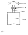
- the internal combustion engine shown consists of an engine block 1 Drive torque is arranged in the interior of the engine block 1 and in the drawing not shown piston-connecting rod assemblies on the crankshaft 2 transferred. On the crankshaft 2 is outside of the engine block 1 Pulley 3 arranged. This first pulley 3 does not drive one either belt drive shown in more detail.
- This belt drive is again called Drive source effective for at least one auxiliary unit of the internal combustion engine.
- the belt drive is in each case with another, on the respective auxiliary unit arranged pulley in operative connection.
- a clutch 4 arranged in the drive train is between the crankshaft 2 and the first one connected to it Pulley 3 a clutch 4 arranged.
- this clutch 4 is provided directly in the contour of the crankshaft 2.
- the clutch 4 can also be integrated in the first pulley 3.
- the Coupling can be designed in various ways, for example as Magnetic clutch or as a centrifugal clutch. Regardless of the specific This coupling 4 is designed for the functionality of the device essential that the clutch 4 can be actuated depending on the crankshaft speed. For this actuation and the necessary detection of the speed preferably used the existing engine control unit.
- the clutch 4 When the internal combustion engine starts, the clutch 4 is first disengaged. In this operating state is the torque path from the crankshaft 2 to Pulley 3 interrupted. The belt running on this pulley 3, the therefore acts as a drive for the subordinate auxiliary units no drive, so that the auxiliary units from the drive torque of the crankshaft 2 are uncoupled. Thus, vibrations on the belt drive and the Ancillaries largely avoided.
- a successful start of the Internal combustion engine which by exceeding a predetermined speed (e.g. the Idle speed) can be seen, the clutch 4 is engaged and the Auxiliary drive now runs in a manner known per se.
Landscapes
- Engineering & Computer Science (AREA)
- Chemical & Material Sciences (AREA)
- Combustion & Propulsion (AREA)
- Mechanical Engineering (AREA)
- General Engineering & Computer Science (AREA)
- Output Control And Ontrol Of Special Type Engine (AREA)
- Pulleys (AREA)
- Devices For Conveying Motion By Means Of Endless Flexible Members (AREA)
Abstract
Description
Claims (8)
- Vorrichtung zum Antrieb von mindestens einem Nebenaggregat einer Brennkraftmaschine, wobei das Antriebsdrehmoment der Brennkraftmaschine über die Kurbelwelle auf eine erste, mit der Kurbelwelle verbundene Riemenscheibe und von dieser mittels Riementrieb auf mindestens eine weitere, als Antrieb eines Nebenaggregates wirksame Riemenscheibe übertragen wird,
dadurch gekennzeichnet,
daß im Antriebsstrang zwischen der Kurbelwelle (2) und der, mit dieser Kurbelwelle (2) verbundenen ersten Riemenscheibe (3) eine Kupplung (4) angeordnet ist. - Vorrichtung nach Anspruch 1,
dadurch gekennzeichnet,
daß die Kupplung (4) in der, mit der Kurbelwelle (2) verbundenen ersten Riemenscheibe (3) integriert ist. - Vorrichtung nach Anspruch 1,
dadurch gekennzeichnet,
daß die Kupplung (4) eine Magnetkupplung ist. - Vorrichtung nach Anspruch 1,
dadurch gekennzeichnet,
daß die Kupplung (4) eine Fliehkraftkupplung ist. - Vorrichtung nach Anspruch 1,
dadurch gekennzeichnet,
daß die Kupplung (4) in Abhängigkeit der Kurbelwellendrehzahl betätigbar ist. - Vorrichtung nach den Ansprüchen 1 und 5,
dadurch gekennzeichnet,
daß die Betätigung der Kupplung (4) durch das Motorsteuergerät ausgelöst wird. - Vorrichtung nach den Ansprüchen 1 und 5,
dadurch gekennzeichnet,
daß die Kupplung (4) beim Start der Brennkraftmaschine ausgekuppelt wird. - Vorrichtung nach den Ansprüchen 1 und 5,
dadurch gekennzeichnet,
daß die Kupplung (4) beim Überschreiten der Leerlaufdrehzahl eingekuppelt wird.
Applications Claiming Priority (2)
| Application Number | Priority Date | Filing Date | Title |
|---|---|---|---|
| DE2000107356 DE10007356A1 (de) | 2000-02-18 | 2000-02-18 | Vorrichtung zum Antrieb von mindestens einem Nebenaggregat einer Brennkraftmaschine |
| DE10007356 | 2000-02-18 |
Publications (2)
| Publication Number | Publication Date |
|---|---|
| EP1126143A2 true EP1126143A2 (de) | 2001-08-22 |
| EP1126143A3 EP1126143A3 (de) | 2002-07-31 |
Family
ID=7631377
Family Applications (1)
| Application Number | Title | Priority Date | Filing Date |
|---|---|---|---|
| EP01102135A Ceased EP1126143A3 (de) | 2000-02-18 | 2001-02-01 | Vorrichtung zum Antrieb von mindestens einem Nebenaggregat einer Brennkraftmaschine |
Country Status (2)
| Country | Link |
|---|---|
| EP (1) | EP1126143A3 (de) |
| DE (1) | DE10007356A1 (de) |
Cited By (1)
| Publication number | Priority date | Publication date | Assignee | Title |
|---|---|---|---|---|
| WO2004101973A1 (de) * | 2003-05-17 | 2004-11-25 | Ina-Schaeffler Kg | Vorrichtung für zusatzaggregate einer brennkraftmaschine |
Families Citing this family (3)
| Publication number | Priority date | Publication date | Assignee | Title |
|---|---|---|---|---|
| DE10202353B4 (de) * | 2002-01-23 | 2007-07-19 | Bayerische Motoren Werke Ag | Verfahren und Vorrichtung zum Betreiben von einem Verbrennungsmotor zuschaltbaren Nebenaggregaten |
| DE102013209291A1 (de) | 2013-05-21 | 2014-11-27 | Schaeffler Technologies Gmbh & Co. Kg | Kupplungsanordnung für einen Nebenaggregatetrieb und Verfahren zum Betrieb einer Kupplungsanordnung |
| DE102013223425A1 (de) | 2013-11-18 | 2015-05-21 | Schaeffler Technologies AG & Co. KG | Kupplungsanordnung für einen Nebenaggregatetrieb und Verfahren zum Betrieb einer Kupplungsanordnung |
Citations (2)
| Publication number | Priority date | Publication date | Assignee | Title |
|---|---|---|---|---|
| DE4309548A1 (de) | 1993-03-24 | 1994-09-29 | Schaeffler Waelzlager Kg | Antrieb von mindestens einem Zusatzaggregat einer Brennkraftmaschine |
| EP0652626A1 (de) | 1993-11-09 | 1995-05-10 | Lyndon Geoffrey Rees | Zusammenbau eines Elektrogenerators |
Family Cites Families (11)
| Publication number | Priority date | Publication date | Assignee | Title |
|---|---|---|---|---|
| US3941225A (en) * | 1974-05-20 | 1976-03-02 | Maclean-Fogg Lock Nut Company | Speed limiting accessory drive system and apparatus therefor |
| EP0136384A1 (de) * | 1983-10-03 | 1985-04-10 | Canadian Fram Limited | Riemenscheibenkupplung für Motorkurbelwelle |
| DE3522988A1 (de) * | 1984-12-13 | 1986-06-26 | Claudius Dr. 5000 Köln Kaniut jun. | Split - motor fuer kraftfahrzeuge mit geteilter kurbelwelle und motor - querwelle fuer hilfsgeraete - antriebe |
| GB9420741D0 (en) * | 1994-10-14 | 1994-11-30 | Litens Automotive Inc | Crankshaft decoupler |
| DE19529740A1 (de) * | 1995-08-12 | 1997-02-13 | Bayerische Motoren Werke Ag | Brennkraftmaschine mit einer elektrischen Anlaßeinrichtung |
| DE19621337A1 (de) * | 1996-05-28 | 1997-12-04 | Bosch Gmbh Robert | Antriebssystem für ein Nebenaggregat |
| DE19750497A1 (de) * | 1997-06-25 | 1999-01-28 | Bosch Gmbh Robert | Getriebe für Nebenaggregate in Kraftfahrzeugen |
| JPH1162612A (ja) * | 1997-08-07 | 1999-03-05 | Mitsubishi Motors Corp | 補機駆動装置 |
| DE19748423A1 (de) * | 1997-11-03 | 1999-02-18 | Daimler Benz Ag | Vorrichtung zum Betreiben von Nebenaggregaten eines Kraftfahrzeuges und Verfahren zum Betreiben der Nebenaggregate in bestimmten Betriebszuständen |
| DE19953940A1 (de) * | 1998-11-17 | 2000-05-25 | Bosch Gmbh Robert | Antriebsaggregat für ein Kraftfahrzeug |
| DE19931963A1 (de) * | 1999-07-12 | 2001-01-18 | Audi Ag | Antriebsvorrichtung |
-
2000
- 2000-02-18 DE DE2000107356 patent/DE10007356A1/de not_active Withdrawn
-
2001
- 2001-02-01 EP EP01102135A patent/EP1126143A3/de not_active Ceased
Patent Citations (2)
| Publication number | Priority date | Publication date | Assignee | Title |
|---|---|---|---|---|
| DE4309548A1 (de) | 1993-03-24 | 1994-09-29 | Schaeffler Waelzlager Kg | Antrieb von mindestens einem Zusatzaggregat einer Brennkraftmaschine |
| EP0652626A1 (de) | 1993-11-09 | 1995-05-10 | Lyndon Geoffrey Rees | Zusammenbau eines Elektrogenerators |
Cited By (2)
| Publication number | Priority date | Publication date | Assignee | Title |
|---|---|---|---|---|
| WO2004101973A1 (de) * | 2003-05-17 | 2004-11-25 | Ina-Schaeffler Kg | Vorrichtung für zusatzaggregate einer brennkraftmaschine |
| US7347309B2 (en) | 2003-05-17 | 2008-03-25 | Ina-Schaeffler Kg | Device for auxiliary units of an internal combustion engine |
Also Published As
| Publication number | Publication date |
|---|---|
| EP1126143A3 (de) | 2002-07-31 |
| DE10007356A1 (de) | 2001-08-23 |
Similar Documents
| Publication | Publication Date | Title |
|---|---|---|
| DE2925675C2 (de) | ||
| DE102012109852B4 (de) | Antriebsstrang eines Kraftfahrzeugs mit Verbrennungsmotor und Starter-Generator | |
| DE19704786C1 (de) | Einrichtung zum Ausgleich von Wechselmomenten und von Schwingungen im Antriebsstrang eines Kraftfahrzeuges mit integriertem Startergenerator | |
| DE10232312A1 (de) | Antriebssystem für ein Kraftfahrzeug mit wenigstens einem elektrischen Motor/Generator und mit wenigstens einer Kolbenbrennkraftmaschine | |
| DE19748423A1 (de) | Vorrichtung zum Betreiben von Nebenaggregaten eines Kraftfahrzeuges und Verfahren zum Betreiben der Nebenaggregate in bestimmten Betriebszuständen | |
| EP1971762B1 (de) | Steuerkettentrieb mit integriertem elektromotor | |
| DE102020116011A1 (de) | Hybridantriebsvorrichtung mit drehfest verbundenem Rotor | |
| DE102006025376A1 (de) | Kraftfahrzeugnebenaggregatantriebssystem und Verfahren zum Betrieb | |
| DE102008007184A1 (de) | Maschine, die ein Stromversorgungssystem aufweist und Verfahren dafür | |
| DE102015214551A1 (de) | Verfahren und Vorrichtung zur Steuerung eines Wiederstartes eines Verbrennungsmotors bei einem Austritt eines mit einem Schaltgetriebe ausgebildeten Fahrzeuges aus einem Segelbetrieb | |
| DE102008008005A1 (de) | Antriebsmodul | |
| DE10007356A1 (de) | Vorrichtung zum Antrieb von mindestens einem Nebenaggregat einer Brennkraftmaschine | |
| DE102017217874B4 (de) | Parallele Hybridantriebsstranganordnung, Fahrzeug und Verfahren zum Anlassen eines Verbrennungsmotors einer parallelen Hybridantriebsstranganordnung | |
| DE19727595A1 (de) | Verfahren und Vorrichtung zum Starten einer Brennkraftmaschine mit Zweimassenschwungrad | |
| DE102019116632A1 (de) | Antriebsstrangvorrichtung und Verfahren zur Verringerung von Drehschwingungen in einem Antriebsstrang | |
| DE60115747T2 (de) | Vorrichtung zur Erzeugung von Wechselstrom für Kraftfahrzeuge | |
| DE102019111481A1 (de) | Steuervorrichtung und Verfahren zum Betrieb eines Hybridantriebs | |
| DE102011103771A1 (de) | Antriebsbaugruppe | |
| WO2007128260A1 (de) | Verfahren zum betreiben eines kraftfahrzeugantriebsstrangs | |
| DE112020002277T5 (de) | Isolationsvorrichtung mit zwei oder mehr Federn in Serie | |
| WO2020069903A1 (de) | Kraftfahrzeugantriebsvorrichtung | |
| DE19907852A1 (de) | Generatorsystem | |
| DE102018207816A1 (de) | Elektrischer Antriebsmotor mit einem Drehschwingungsdämpfer/-tilger mit einem Fliehkraftpendelsystem | |
| EP3665375B1 (de) | Antriebsvorrichtung für ein motorrad | |
| DE102013209291A1 (de) | Kupplungsanordnung für einen Nebenaggregatetrieb und Verfahren zum Betrieb einer Kupplungsanordnung |
Legal Events
| Date | Code | Title | Description |
|---|---|---|---|
| PUAI | Public reference made under article 153(3) epc to a published international application that has entered the european phase |
Free format text: ORIGINAL CODE: 0009012 |
|
| AK | Designated contracting states |
Kind code of ref document: A2 Designated state(s): AT BE CH CY DE DK ES FI FR GB GR IE IT LI LU MC NL PT SE TR |
|
| AX | Request for extension of the european patent |
Free format text: AL;LT;LV;MK;RO;SI |
|
| RIN1 | Information on inventor provided before grant (corrected) |
Inventor name: LIANG, JAMES, DIPL.-ING. |
|
| PUAL | Search report despatched |
Free format text: ORIGINAL CODE: 0009013 |
|
| AK | Designated contracting states |
Kind code of ref document: A3 Designated state(s): AT BE CH CY DE DK ES FI FR GB GR IE IT LI LU MC NL PT SE TR |
|
| AX | Request for extension of the european patent |
Free format text: AL;LT;LV;MK;RO;SI |
|
| RIC1 | Information provided on ipc code assigned before grant |
Free format text: 7F 02B 67/00 A, 7F 02B 67/06 B |
|
| 17P | Request for examination filed |
Effective date: 20030131 |
|
| AKX | Designation fees paid |
Designated state(s): AT BE CH CY DE DK ES FI FR GB GR IE IT LI LU MC NL PT SE TR |
|
| 17Q | First examination report despatched |
Effective date: 20050518 |
|
| APBN | Date of receipt of notice of appeal recorded |
Free format text: ORIGINAL CODE: EPIDOSNNOA2E |
|
| APBR | Date of receipt of statement of grounds of appeal recorded |
Free format text: ORIGINAL CODE: EPIDOSNNOA3E |
|
| APAF | Appeal reference modified |
Free format text: ORIGINAL CODE: EPIDOSCREFNE |
|
| APBT | Appeal procedure closed |
Free format text: ORIGINAL CODE: EPIDOSNNOA9E |
|
| STAA | Information on the status of an ep patent application or granted ep patent |
Free format text: STATUS: THE APPLICATION HAS BEEN REFUSED |
|
| 18R | Application refused |
Effective date: 20081219 |