EP1126080A2 - Method for driving a calender roll, and a calender roll - Google Patents
Method for driving a calender roll, and a calender roll Download PDFInfo
- Publication number
- EP1126080A2 EP1126080A2 EP01101774A EP01101774A EP1126080A2 EP 1126080 A2 EP1126080 A2 EP 1126080A2 EP 01101774 A EP01101774 A EP 01101774A EP 01101774 A EP01101774 A EP 01101774A EP 1126080 A2 EP1126080 A2 EP 1126080A2
- Authority
- EP
- European Patent Office
- Prior art keywords
- liquid
- calender roll
- mass
- roll
- air
- Prior art date
- Legal status (The legal status is an assumption and is not a legal conclusion. Google has not performed a legal analysis and makes no representation as to the accuracy of the status listed.)
- Granted
Links
Images


Classifications
-
- F—MECHANICAL ENGINEERING; LIGHTING; HEATING; WEAPONS; BLASTING
- F16—ENGINEERING ELEMENTS AND UNITS; GENERAL MEASURES FOR PRODUCING AND MAINTAINING EFFECTIVE FUNCTIONING OF MACHINES OR INSTALLATIONS; THERMAL INSULATION IN GENERAL
- F16C—SHAFTS; FLEXIBLE SHAFTS; ELEMENTS OR CRANKSHAFT MECHANISMS; ROTARY BODIES OTHER THAN GEARING ELEMENTS; BEARINGS
- F16C13/00—Rolls, drums, discs, or the like; Bearings or mountings therefor
-
- D—TEXTILES; PAPER
- D21—PAPER-MAKING; PRODUCTION OF CELLULOSE
- D21G—CALENDERS; ACCESSORIES FOR PAPER-MAKING MACHINES
- D21G1/00—Calenders; Smoothing apparatus
-
- D—TEXTILES; PAPER
- D21—PAPER-MAKING; PRODUCTION OF CELLULOSE
- D21G—CALENDERS; ACCESSORIES FOR PAPER-MAKING MACHINES
- D21G1/00—Calenders; Smoothing apparatus
- D21G1/0073—Accessories for calenders
- D21G1/008—Vibration-preventing or -eliminating devices
-
- D—TEXTILES; PAPER
- D21—PAPER-MAKING; PRODUCTION OF CELLULOSE
- D21G—CALENDERS; ACCESSORIES FOR PAPER-MAKING MACHINES
- D21G1/00—Calenders; Smoothing apparatus
- D21G1/02—Rolls; Their bearings
Definitions
- the invention relates to a method for operating a Calender roll rotating with at least one another calender roll of a roll stack interacts, wherein at least one calender roll of the roll stack has an elastic covering. Furthermore concerns the invention a calender roll with a roll shell and a supply connection arrangement.
- Such calender rolls are often used as center rolls used in a calender, so they form one Part of a roll stack. Form adjacent rolls here nips through which a material web is guided, to there with increased pressure and possibly increased Temperature to be applied.
- rollers are widely used when treating a paper web, the following used as an example to illustrate the invention shall be. The same problem arises also with other material webs.
- calenders usually act in such calenders “soft” rollers together with “hard” rollers. Scattered two “soft” rollers also work together.
- the soft rollers are here with a plastic covering based. It has now been observed that after a certain Operating time of such a calender a so-called Barring can be observed. That barring appearance on the one hand causes an undesirable strip-like Pattern on the paper web. You can get these stripes though also as stripe-shaped markings on the elastic Recognize rollers with the plastic coverings.
- the soft rollers become polygonal, so to speak. From a certain These barrings add strength or intensity Committee on the paper web.
- the corresponding roller or the corresponding rollers must then be revised to eliminate the deformation of the plastic covering. Usually this is done by turning off the Roller connected.
- the invention has for its object the barring appearance to diminish.
- This task is carried out in a method of the type mentioned at the beginning Kind solved in that the mass of the calender roll changed during operation.
- a roll stack made up of several rolls has a variety of natural frequencies. With these There are natural frequencies, for example, natural bending frequencies, who are less interested in the present case, and modes of natural vibration, which result from the vibrating roller masses on the spring and damper systems result from those located between the rollers Plastic coverings and next to it through the roller bearings are formed.
- a running calender creates now excitation forces, their frequencies with the roller speeds related and in first approximation each correspond to multiples of the rotational frequencies. This Excitation forces can have many causes, for example Inhomogeneities, anisotropies or geometry errors. Fluctuations in the thickness of the calender can also occur excite the continuous paper web the roller stack.
- the mass is preferably changed during operation continuously. So you make sure that the crowd the calender roll continuously during operation decreases. This means that the resonance frequency is also continuous changed so that one is relatively safe the formation of a stationary resonance frequency can avoid causing unwanted barring leads.
- the mass of the calender roll is advantageously increased 10 to 15% of their basic mass.
- the basic mass is, so to speak the "empty weight" of the calender roll.
- a predetermined one is preferably carried out during operation Amount of fluid and this amount of fluid then off again.
- the liquid has that Advantage that due to the centrifugal force, which prevails inside the calender roll during operation, relatively quickly over the entire axial length of the calender roll and spreads over its entire inner circumference, so that by the supply and removal of a Liquid cannot give rise to local unbalances.
- the In and out of liquid is known per se for example for cooling or heating purposes. In the known However, one tries to measure the mass of the case to keep pumped liquid constant. According to the invention on the other hand, it is envisaged that with help the liquid changes the mass of the calender roll achieved.
- the liquid is preferably placed on the inner wall of the roll shell. So you conduct the liquid deliberately so that they are as possible without training Air layer vibrationally with the calender roller connects. This ensures that the liquid mass is involved in the vibration movement. There would be air between the liquid and the calender roll could remain because of their compressibility swing like a feather differently than that Calender roll itself.
- the liquid is preferably left on the roller rotate. It may be necessary for this that there are drivers in the roller for the liquid. So that the liquid is also in terms of the rotational movement of the roller is a "component" of the Roller is therefore to be attributed to its mass in every respect.
- the liquid is preferably blown with the help from compressed air from the roller.
- compressed air you can of course use another compressed gas.
- compressed air is advantageous for cost reasons. In order to you save yourself expensive pumping mechanisms that either the liquid from inside the calender roll pump or suck. With the help of compressed air you can ensure that even when emptying the calender roll, i.e. when draining the liquid, always the contact between the liquid and the calender roll preserved.
- the occurrence of air in is preferably used the liquid discharge line as a signal for a new one Fill the calender roll with liquid.
- oneself complex control devices which monitor whether the calender roll is in sufficient Measure has been emptied. All that is required is that you check whether in the liquid discharge line, which can otherwise be identical to the liquid supply line, Air occurs or not. This Checking can also be done, for example, that you have the pressure difference for the exhaust air determined. The moment there is enough fluid the air has been removed from the calender roll, so to speak Flow freely from the entrance to the exit , there will be a sharp drop in pressure, which is called Signal can be used that the roller is now in sufficient Dimensions has been emptied.
- the liquid is advantageously tempered.
- the calender roll itself has an elastic Covering or covering, it is with the help of the liquid possible heat, for example, by the Flexing work of the elastic covering arises. Because the heat is not uniform, but is discharged virtually in batches, there will be a constant Only achieve temperature in exceptional cases to let. However, this is not necessary because it basically just comes down to overheating to avoid the topping.
- the change in mass of the calender roll is preferably equalized by bending compensation rollers and / or weight compensation cylinders the calender roll. If the mass of the calender roll by supplying foreign masses increases, then of course the conditions change, especially the pressure load, in the individual Nips of the roll stack. This in itself undesirable However, the effect can be controlled by the upper and lower bending compensation rollers in the roll stack and the weight compensation cylinder of the center rolls, with which the vast majority today the modern calender is equipped, balanced become.
- the task is also the beginning of a calender roll mentioned type solved in that the supply connection arrangement with a mass change device connected is.
- a supply connector assembly is from rolls known that heated with the help of tempered liquid or be cooled. This point of view, however, is only minor in the present invention Importance. According to the invention, care is taken with the supply connection arrangement that the mass of the Calender roll by feeding or removing one "Foreign mass" changed. So you reach into the vibration system of the roll stack and changes continuously or the natural frequency from time to time. In order to the formation of resonance frequencies is disturbed and barring formation avoided or at least drastically reduced.
- the mass change device preferably feeds alternately air and a liquid in the supply connection arrangement on. When the liquid is fed the mass increases.
- the mass change device with the help of air the liquid repressed. So you can reduce the air Use the mass of the calender roll.
- the feed directions are preferably of liquid and air opposed to each other. So you have a liquid line and an air line, so to speak. This has the advantage of being on every line a pump tailored to the respective fluid (or another pressure generator) can provide. Complicated Valves or other control mechanisms can largely omitted.
- the supply connection arrangement preferably has one Liquid connection on which a baffle plate is opposite, the predetermined up to a crack Thickness reaches the inner wall of the roll shell.
- the supply connection arrangement has an air connection that the baffle plate enforced.
- the air fed in then works radially from the inside to the outside on the inside wall of the roll shell liquid and it can through the gap between the baffle plate and the inner wall of the Push the roller jacket back again.
- the two media Air and liquid have defined accordingly Pressure attack directions, with the help of which enlargement and reducing the mass of the calender roll can be controlled very well.
- a liquid sensor is advantageous in the air connection arranged. So you can easily fill the process finish and evaluate as a corresponding signal, if larger quantities of liquids come out of the air pipe emerge.
- Air sensor is arranged. You can use this sensor to control the emptying process. This is finished when air from the ducts of the baffle plate and thus enters the liquid connection.
- the mass change device a pressure sensor for the air supply exhibit. If the air from the channels of the baffle plate emerges, this is with a measurable pressure difference be connected as a control signal for the Switching off the emptying process can be used can.
- the filling process can of course also be carried out in a similar manner about a measurable pressure difference at escaping water to air is controlled from the air line become.
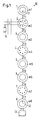
- Fig. 1 shows schematically a calender 10, i.e. one Stack of stacked calender rolls 1-8.
- the top roller 1 and the bottom roller 8 are designed as a bend adjustment roller.
- From the intermediate rolls is the second, fourth and seventh from above as Heating roller formed while the third, fifth and sixth roller are designed as elastic rollers. Adjacent rolls form one between them Nip used to treat a web of material will, i.e. to act on the not shown Material web with pressure and possibly one elevated temperature.
- the bending adjustment rollers with their hydraulic support elements 11, 12 are as Control options another cylinder 13 below the Calender 10 available and if necessary for each the middle rollers 2-7 a weight compensation cylinder 14, for the sake of clarity only for the center roll 2 is shown.
- the calender frame was also omitted.
- Each of the rollers 1-8 has a roller mass m1-m8.
- the calender thus forms 10 a system of a multi-mass oscillator. Operational this results in a correspondingly large number of natural frequencies, each of which is when an excitation frequency is of the same order of magnitude as one Can lead to resonance. It is now assumed that at form a barring at certain resonance frequencies can be in a sequence of stripes on the to treating material web expresses.
- a spring stiffness follows from the measured natural frequency and the roll mass, which can be attributed, for example, to the compression behavior of the elastic coverings.
- the path was chosen, one feed a certain amount of liquid into the roller or to remove it after a certain operating time.
- the liquid mass that can be filled into the center roller 3 Am is 195 kg / m.
- Liquid preferably water.
- the change the roller mass can run relatively quickly, so that a certain pattern on the elastic Can not impress the coating.
- the roller 3 has an elastic covering 15.
- the elastic covering 15 is arranged on a roller jacket 16, which encloses a hollow interior 17.
- On the front is the interior by means of tenon washers 18 closed, which merge into roll neck 19.
- the Roll pins 19 have in a manner known per se and Show a supply connection arrangement with a first channel 20 and a second channel 21.
- the two Channels 20, 21 form a supply connection arrangement and are about a rotary feedthrough, not shown with a mass change device 22 connected.
- the mass change device 22 has a liquid pump 23 between the first Channel 20 and a liquid reservoir 24 are arranged is. The pump 23 is therefore able to hold the liquid from the liquid reservoir 24 into the interior 17 to pump the calender roll 3.
- the mass change device 22 also has one second pump 25, which compresses air.
- This pump 25 is connected to the second channel 21, which is also is directed into the interior 17. The pump 25 is therefore able to close the interior 17 with compressed air fill.
- a baffle plate 26 is provided.
- the baffle plate 26 rotates with the roller jacket 16 With. It points towards the first channel Side webs 27 on, between them radially outwards form running channels 28. In the space between Dust disk 26 and cone disk 18 fed liquid is thus through the webs 27 radially outwards directed and at the same time on the speed of the Calender roll 3 accelerated.
- the second channel 21 passes through the baffle plate 26, so opens approximately in the radial center of the interior 17.
- the baffle plate 26 forms the inner wall of the roller shell a relatively narrow gap 29. This gap 29 is dimensioned so that liquid that flows through the first Channel 20 and channels 28 are fed immediately comes to rest on the inner wall of the roll shell 16. So you avoid that between the liquid and air remains in the roll shell 16.
- Filling and emptying can be done relatively quickly. For example, one cycle can be within one or two minutes.
- the roller jacket 16 now has peripheral bores 36 in which a heat transfer medium can circulate.
- the heat transfer medium is, for example, on the other Roll end in and out. But the elastic is missing Topping 15.
- the liquid that the Interior 17 supplied and discharged from there will be used to certain amounts of heat from the inside out or from the outside in to transport.
- the liquid for example generated by flexing Dissipate heat. This heat dissipation does not take place continuously. But it is enough to overheat to avoid covering 15.
- the focus is on the change in the mass of the rollers 3, 4.
Abstract
Es wird ein Verfahren zum Betreiben einer Kalanderwalze (3) angegeben, die rotierend mit mindestens einer weiteren Kalanderwalze eines Walzenstapels zusammenwirkt, wobei mindestens eine Kalanderwalze des Walzenstapels einen elastischen Belag (15) aufweist. Ferner wird eine Kalanderwalze mit einem Walzenmantel (16) und einer Versorgungsanschlußanordnung (20, 21) angegeben. Man möchte eine Barringbildung im Betrieb vermeiden können. Hierzu ändert man die Masse der Kalanderwalze (3) während des Betriebs. Dazu ist die Versorgungsanschlußanordnung (20, 21) mit einer Massenveränderungseinrichtung (22) verbunden. <IMAGE>The invention relates to a method for operating a calender roll (3) which interacts in rotation with at least one other calender roll of a roll stack, at least one calender roll of the roll stack having an elastic covering (15). Furthermore, a calender roll with a roll jacket (16) and a supply connection arrangement (20, 21) is specified. You want to be able to avoid barring in the company. To do this, change the mass of the calender roll (3) during operation. For this purpose, the supply connection arrangement (20, 21) is connected to a mass change device (22). <IMAGE>
Description
Die Erfindung betrifft ein Verfahren zum Betreiben einer Kalanderwalze, die rotierend mit mindestens einer weiteren Kalanderwalze eines Walzenstapels zusammenwirkt, wobei mindestens eine Kalanderwalze des Walzenstapels einen elastischen Belag aufweist. Ferner betrifft die Erfindung eine Kalanderwalze mit einem Walzenmantel und einer Versorgungsanschlußanordnung.The invention relates to a method for operating a Calender roll rotating with at least one another calender roll of a roll stack interacts, wherein at least one calender roll of the roll stack has an elastic covering. Furthermore concerns the invention a calender roll with a roll shell and a supply connection arrangement.
Derartige Kalanderwalzen werden vielfach als Mittelwalzen in einem Kalander eingesetzt, bilden also einen Teil eines Walzenstapels. Benachbarte Walzen bilden hierbei Nips, durch die eine Materialbahn geführt wird, um dort mit erhöhtem Druck und gegebenenfalls erhöhter Temperatur beaufschlagt zu werden.Such calender rolls are often used as center rolls used in a calender, so they form one Part of a roll stack. Form adjacent rolls here nips through which a material web is guided, to there with increased pressure and possibly increased Temperature to be applied.
Eine weit verbreitete Anwendung finden derartige Walzen bei der Behandlung einer Papierbahn, die im folgenden als Beispiel zur Erläuterung der Erfindung verwendet werden soll. Die gleiche Problematik ergibt sich aber auch bei anderen Materialbahnen. Such rollers are widely used when treating a paper web, the following used as an example to illustrate the invention shall be. The same problem arises also with other material webs.
In derartigen Kalandern wirken in der Regel sogenannte "weiche" Walzen mit "harten" Walzen zusammen. Vereinzelt wirken auch zwei "weiche" Walzen zusammen. Die weichen Walzen sind hierbei mit einem Kunststoffbelag bezogen. Man hat nun beobachtet, daß nach einer gewissen Betriebszeit derartiger Kalander ein sogenanntes Barring zu beobachten ist. Diese Barring-Erscheinung bewirkt einerseits ein unerwünschtes streifenförmiges Muster auf der Papierbahn. Man kann diese Streifen aber auch als streifenförmige Markierungen an den elastischen Walzen mit den Kunststoffbelägen erkennen. Die weichen Walzen werden sozusagen vieleckig. Ab einer gewissen Stärke oder Intensität führen diese Barrings zu Ausschuß bei der Papierbahn. Die entsprechende Walze oder die entsprechenden Walzen müssen dann überarbeitet werden, um die Verformung des Kunststoffbelages zu beseitigen. In der Regel ist dies mit einem Abdrehen der Walze verbunden.So-called calenders usually act in such calenders "soft" rollers together with "hard" rollers. Scattered two "soft" rollers also work together. The soft rollers are here with a plastic covering based. It has now been observed that after a certain Operating time of such a calender a so-called Barring can be observed. That barring appearance on the one hand causes an undesirable strip-like Pattern on the paper web. You can get these stripes though also as stripe-shaped markings on the elastic Recognize rollers with the plastic coverings. The soft rollers become polygonal, so to speak. From a certain These barrings add strength or intensity Committee on the paper web. The corresponding roller or the corresponding rollers must then be revised to eliminate the deformation of the plastic covering. Usually this is done by turning off the Roller connected.
Der Erfindung liegt die Aufgabe zugrunde, die Barring-Erscheinung zu vermindern.The invention has for its object the barring appearance to diminish.
Diese Aufgabe wird bei einem Verfahren der eingangs genannten Art dadurch gelöst, daß man die Masse der Kalanderwalze während des Betriebs verändert.This task is carried out in a method of the type mentioned at the beginning Kind solved in that the mass of the calender roll changed during operation.
Hierbei geht man von folgenden Überlegungen aus:The following considerations are used:
Ein Walzenstapel, der aus mehreren Walzen gebildet wird, hat eine Vielzahl von Eigenfrequenzen. Bei diesen Eigenfrequenzen gibt es beispielsweise Biegeeigenfrequenzen, die im vorliegenden Fall weniger interessieren, und Eigenschwingungsformen, die sich aus den schwingenden Walzenmassen auf den Feder- und Dämpfersystemen ergeben, die durch die zwischen den Walzen befindlichen Kunststoffbeläge und daneben durch die Walzenlagerungen gebildet sind. Ein laufender Kalander erzeugt nun Erregerkräfte, deren Frequenzen mit den Walzendrehzahlen zusammenhängen und in erster Nährung jeweils vielfachen der Drehfrequenzen entsprechen. Diese Erregerkräfte können viele Ursachen haben, beispielsweise Inhomogenitäten, Anisotropien oder Geometriefehler. Auch können Papierdickenschwankungen der den Kalander durchlaufenden Papierbahn den Walzenstapel erregen. Wenn nun eine dieser Erregerfrequenzen auf eine Eigenfrequenz trifft, so antwortet das Schwingungssystem mit vergrößerten Schwingungsausschlägen. Aufgrund der Vielzahl der möglichen Erreger und der Vielzahl der möglichen Eigenschwingungsformen lassen sich diese Resonanzstellen konstruktiv praktisch nicht umgehen. In der Regel ist das Schwingungssystem auch so stark gedämpft und die Erregerkräfte sind so klein, daß die resultierende Schwingbewegung nicht unmittelbar stört. Erst über einen mehr oder weniger längeren Zeitraum prägen sich diese Schwingungsbewegungen jedoch in die Kunststoffbeläge der elastischen Walze ein. Man kann vielfach beobachten, daß die nächstliegenden ganzzahligen Vielfachen der Schwingungsfrequenz als Muster auf den Walzen eingeprägt werden. Hierdurch erfolgt wiederum eine Rückkopplung der Schwingung. Die Schwingungsausschläge nehmen dann expotentiell zu. Sie äußern sich einerseits in einem erhöhten Schallpegel (bis mehr als 115 dB (A)) und andererseits in periodischen Dickenschwankungen der durchlaufenden Papierbahn, die - wie oben erwähnt - zu Ausschuß führen. Erfindungsgemäß wird nun zur Vermeidung des oben beschriebenen Rückkopplungseffektes der Entstehungsmechanismus der periodischen Belagwelligkeit gestört. Um zu vermeiden, daß sich ein konstantes ganzzahliges Muster mit einer Frequenz nahe der Eigenfrequenz des Systems auf den Walzen einprägt, greift man mit der Veränderung der Masse der Kalanderwalze in das Schwingungssystem ein und verändert die entsprechenden Eigenfrequenzen. Durch eine Veränderung der Eigenfrequenzen sorgt man dafür, daß das schwingende System nicht über einen längeren Zeitraum mit einer Resonanzfrequenz betrieben werden kann, die wiederum schädliche Auswirkungen, insbesondere im Hinblick auf die Barringbildung, haben kann. In den meisten Fällen wird man zur Veränderung der Masse der Kalanderwalze tatsächlich Massen zu- bzw. abführen. In manchen Fällen wird es allerdings ausreichen, wenn man die Massenverteilung innerhalb der Kalanderwalze verändert, d.h. beispielsweise Massen von radial innen nach radial außen verlagert. Eine derartige Veränderung beeinflußt unter anderem das Trägheitsmoment.A roll stack made up of several rolls has a variety of natural frequencies. With these There are natural frequencies, for example, natural bending frequencies, who are less interested in the present case, and modes of natural vibration, which result from the vibrating roller masses on the spring and damper systems result from those located between the rollers Plastic coverings and next to it through the roller bearings are formed. A running calender creates now excitation forces, their frequencies with the roller speeds related and in first approximation each correspond to multiples of the rotational frequencies. This Excitation forces can have many causes, for example Inhomogeneities, anisotropies or geometry errors. Fluctuations in the thickness of the calender can also occur excite the continuous paper web the roller stack. If now one of these excitation frequencies to a Natural frequency hits, so the vibration system answers with increased vibrations. Because of the multitude of possible pathogens and the multitude of These resonance points can be made into possible natural vibration forms constructively practically bypass. In As a rule, the vibration system is damped so much and the excitation forces are so small that the resulting one Swinging movement does not directly interfere. Only over a more or less long period however, these vibrational movements are noticeable in the Plastic coverings of the elastic roller. One can often observe that the closest integers Multiples of the oscillation frequency as a pattern are impressed on the rollers. This in turn takes place a feedback of the vibration. The vibration rashes then increase exponentially. You express yourself on the one hand in an increased sound level (up to more than 115 dB (A)) and on the other hand in periodic fluctuations in thickness the continuous paper web, which - like mentioned above - lead to committee. According to the invention now to avoid the feedback effect described above the mechanism of origin of the periodic Base ripple disturbed. To avoid that itself a constant integer pattern with a frequency near the natural frequency of the system on the rollers impresses, one intervenes with the change in the mass of the Calender roller in the vibration system and changed the corresponding natural frequencies. By a Changing the natural frequencies ensures that the vibrating system does not last for a long period of time can be operated with a resonance frequency, which in turn has harmful effects, especially in With regard to the formation of barring. In the In most cases one is going to change the mass of the Calender roller actually feed or discharge masses. In in some cases, however, it will be sufficient if you the mass distribution within the calender roll changes, i.e. for example masses from radially inwards to shifted radially outside. Such a change is affected including the moment of inertia.
Vorzugsweise verändert man die Masse während des Betriebs fortlaufend. Man sorgt also dafür, daß die Masse der Kalanderwalze im Betrieb kontinuierlich zu- oder abnimmt. Damit wird auch fortlaufend die Resonanzfrequenz geändert, so daß man mit relativ großer Sicherheit die Ausbildung einer stationären Resonanzfrequenz vermeiden kann, die zu der unerwünschten Barringbildung führt.The mass is preferably changed during operation continuously. So you make sure that the crowd the calender roll continuously during operation decreases. This means that the resonance frequency is also continuous changed so that one is relatively safe the formation of a stationary resonance frequency can avoid causing unwanted barring leads.
Mit Vorteil erhöht man die Masse der Kalanderwalze um 10 bis 15 % ihrer Grundmasse. Die Grundmasse ist sozusagen das "Leergewicht" der Kalanderwalze. Man hat nun festgestellt, daß man bei Massenveränderungen von ca. 10 bis 15 % der Walzenmasse eine Änderung der Eigenfrequenz der Kalanderwalze in der Größenordnung von 4 bis 7 % erzielen kann. Diese Veränderung reicht aus, um eine Barringbildung nicht entstehen zu lassen. The mass of the calender roll is advantageously increased 10 to 15% of their basic mass. The basic mass is, so to speak the "empty weight" of the calender roll. You have now found that with mass changes of approx. 10 to 15% of the roll mass changes the natural frequency the calender roll in the order of 4 to Can achieve 7%. This change is enough to Not to let barring develop.
Vorzugsweise führt man während des Betriebs eine vorbestimmte Flüssigkeitsmenge zu und diese Flüssigkeitsmenge danach wieder ab. Mit Hilfe einer Flüssigkeit läßt sich die Massenveränderung der Kalanderwalze auf einfache Art und Weise erzielen. Die Flüssigkeit hat den Vorteil, daß sie sich aufgrund der Zentrifugalkraft, die im Betrieb im Innern der Kalanderwalze herrscht, relativ schnell über die gesamte axiale Länge der Kalanderwalze und über ihren gesamten Innenumfang ausbreitet, so daß sich durch die Zu- und Abfuhr einer Flüssigkeit keine lokalen Unwuchten ergeben können. Die Zu- und Abführ von Flüssigkeit an sich ist zwar bekannt, beispielsweise zu Kühl- oder Heizzwecken. Im bekannten Fall ist man jedoch bestrebt, die Masse der durchgepumpten Flüssigkeit konstant zu halten. Erfindungsgemäß hingegen ist vorgesehen, daß man mit Hilfe der Flüssigkeit eine Massenveränderung der Kalanderwalze erzielt.A predetermined one is preferably carried out during operation Amount of fluid and this amount of fluid then off again. With the help of a liquid leaves the mass change of the calender roll on simple Achieve way. The liquid has that Advantage that due to the centrifugal force, which prevails inside the calender roll during operation, relatively quickly over the entire axial length of the calender roll and spreads over its entire inner circumference, so that by the supply and removal of a Liquid cannot give rise to local unbalances. The In and out of liquid is known per se for example for cooling or heating purposes. In the known However, one tries to measure the mass of the case to keep pumped liquid constant. According to the invention on the other hand, it is envisaged that with help the liquid changes the mass of the calender roll achieved.
Vorzugsweise legt man die Flüssigkeit an die Innenwand des Walzenmantels an. Man leitet also die Flüssigkeit gezielt so, daß sie sich möglichst ohne Ausbildung einer Luftschicht schwingungstechnisch mit der Kalanderwalze verbindet. Damit stellt man sicher, daß die Flüssigkeitsmasse an der Schwingungsbewegung beteiligt ist. Würde Luft zwischen der Flüssigkeit und der Kalanderwalze verbleiben, könnte diese wegen ihrer Kompressibilität nach Art einer Feder anders schwingen, als die Kalanderwalze selbst.The liquid is preferably placed on the inner wall of the roll shell. So you conduct the liquid deliberately so that they are as possible without training Air layer vibrationally with the calender roller connects. This ensures that the liquid mass is involved in the vibration movement. There would be air between the liquid and the calender roll could remain because of their compressibility swing like a feather differently than that Calender roll itself.
Bevorzugterweise läßt man die Flüssigkeit mit der Walze rotieren. Gegebenenfalls ist es hierzu erforderlich, daß man Mitnehmer in der Walze für die Flüssigkeit vorsieht. Damit wird die Flüssigkeit auch im Hinblick auf die Rotationsbewegung der Walze ein "Bestandteil" der Walze, ist ihrer Masse also auch in jeder Hinsicht zuzurechnen.The liquid is preferably left on the roller rotate. It may be necessary for this that there are drivers in the roller for the liquid. So that the liquid is also in terms of the rotational movement of the roller is a "component" of the Roller is therefore to be attributed to its mass in every respect.
Bevorzugterweise bläst man die Flüssigkeit mit Hilfe von Druckluft aus der Walze aus. Anstelle von Druckluft kann man natürlich auch ein anderes Druckgas verwenden. Druckluft ist jedoch aus Kostengründen von Vorteil. Damit erspart man sich aufwendige Pumpmechanismen, die entweder die Flüssigkeit aus dem Innern der Kalanderwalze abpumpen oder absaugen. Mit Hilfe der Druckluft kann man dafür sorgen, daß auch beim Entleeren der Kalanderwalze, d.h. beim Abführen der Flüssigkeit, immer der Kontakt zwischen der Flüssigkeit und der Kalanderwalze erhalten bleibt.The liquid is preferably blown with the help from compressed air from the roller. Instead of compressed air you can of course use another compressed gas. However, compressed air is advantageous for cost reasons. In order to you save yourself expensive pumping mechanisms that either the liquid from inside the calender roll pump or suck. With the help of compressed air you can ensure that even when emptying the calender roll, i.e. when draining the liquid, always the contact between the liquid and the calender roll preserved.
Vorzugsweise verwendet man das Auftreten von Luft in der Flüssigkeitsabführleitung als Signal für ein erneutes Befüllen der Kalanderwalze mit Flüssigkeit. Damit erspart man sich aufwendige Kontrolleinrichtungen, die überwachen, ob die Kalanderwalze in einem ausreichendem Maß entleert worden ist. Erforderlich ist lediglich, daß man überprüft, ob in der Flüssigkeitsabfuhrleitung, die im übrigen identisch sein kann mit der Flüssigkeitszufuhrleitung, Luft auftritt oder nicht. Diese Überprüfung kann man beispielsweise auch dadurch anstellen, daß man die Druckdifferenz für die Ausblasluft ermittelt. In dem Augenblick, wo genügend Flüssigkeit aus der Kalanderwalze entfernt worden ist, die Luft sozusagen ungehindert vom Eingang zum Ausgang strömen kann, wird ein starker Druckabfall auftreten, der als Signal verwendet werden kann, das die Walze nun in ausreichendem Maße entleert worden ist. The occurrence of air in is preferably used the liquid discharge line as a signal for a new one Fill the calender roll with liquid. In order to one spares oneself complex control devices which monitor whether the calender roll is in sufficient Measure has been emptied. All that is required is that you check whether in the liquid discharge line, which can otherwise be identical to the liquid supply line, Air occurs or not. This Checking can also be done, for example, that you have the pressure difference for the exhaust air determined. The moment there is enough fluid the air has been removed from the calender roll, so to speak Flow freely from the entrance to the exit , there will be a sharp drop in pressure, which is called Signal can be used that the roller is now in sufficient Dimensions has been emptied.
Mit Vorteil wird die Flüssigkeit temperiert. Man kann also die Flüssigkeit erwärmen oder kühlen. Insbesondere dann, wenn die Kalanderwalze selbst einen elastischen Bezug oder Belag aufweist, ist es mit Hilfe der Flüssigkeit möglich, Wärme, die beispielsweise durch die Walkarbeit des elastischen Belages entsteht, abzuführen. Da damit die Wärme nicht gleichförmig, sondern quasi chargenweise abgeführt wird, wird sich eine konstante Temperatur damit nur in Ausnahmefällen erzielen lassen. Dies ist jedoch auch nicht erforderlich, weil es im Grunde genommen nur darauf ankommt, eine Überhitzung des Belages zu vermeiden.The liquid is advantageously tempered. One can so heat or cool the liquid. In particular then when the calender roll itself has an elastic Covering or covering, it is with the help of the liquid possible heat, for example, by the Flexing work of the elastic covering arises. Because the heat is not uniform, but is discharged virtually in batches, there will be a constant Only achieve temperature in exceptional cases to let. However, this is not necessary because it basically just comes down to overheating to avoid the topping.
Vorzugsweise gleicht man die Massenänderung der Kalanderwalze durch Biegeausgleichswalzen und/oder Gewichtskompensationszylinder der Kalanderwalze aus. Wenn man die Masse der Kalanderwalze durch Zufuhr von Fremdmassen erhöht, dann ändern sich natürlich auch die Verhältnisse, insbesondere die Druckbelastung, in den einzelnen Nips des Walzenstapels. Dieser an sich unerwünschte Effekt kann jedoch durch die Steuerung der oberen und unteren im Walzenstapel befindlichen Biegeausgleichswalzen und der Gewichtskompensationszylinder der Mittelwalzen, mit denen heute die überwiegende Anzahl der modernen Kalander ausgerüstet ist, ausgeglichen werden.The change in mass of the calender roll is preferably equalized by bending compensation rollers and / or weight compensation cylinders the calender roll. If the mass of the calender roll by supplying foreign masses increases, then of course the conditions change, especially the pressure load, in the individual Nips of the roll stack. This in itself undesirable However, the effect can be controlled by the upper and lower bending compensation rollers in the roll stack and the weight compensation cylinder of the center rolls, with which the vast majority today the modern calender is equipped, balanced become.
Die Aufgabe wird auch bei einer Kalanderwalze der eingangs genannten Art dadurch gelöst, daß die Versorgungsanschlußanordnung mit einer Massenveränderungseinrichtung verbunden ist. The task is also the beginning of a calender roll mentioned type solved in that the supply connection arrangement with a mass change device connected is.
Eine Versorgungsanschlußanordnung ist von Walzen her bekannt, die mit Hilfe von temperierter Flüssigkeit beheizt oder gekühlt werden. Dieser Gesichtspunkt ist jedoch bei der vorliegenden Erfindung nur von untergeordneter Bedeutung. Erfindungsgemäß sorgt man mit der Versorgungsanschlußanordnung dafür, daß sich die Masse der Kalanderwalze durch Zufuhr oder Abfuhr einer "Fremdmasse" verändert. Damit greift man in das Schwingungssystem des Walzenstapels ein und verändert fortlaufend oder von Zeit zu Zeit die Eigenfrequenz. Damit wird die Ausbildung von Resonanzfrequenzen gestört und die Barringbildung vermieden oder zumindest drastisch vermindert.A supply connector assembly is from rolls known that heated with the help of tempered liquid or be cooled. This point of view, however, is only minor in the present invention Importance. According to the invention, care is taken with the supply connection arrangement that the mass of the Calender roll by feeding or removing one "Foreign mass" changed. So you reach into the vibration system of the roll stack and changes continuously or the natural frequency from time to time. In order to the formation of resonance frequencies is disturbed and barring formation avoided or at least drastically reduced.
Vorzugsweise speist die Massenveränderungseinrichtung abwechselnd Luft und eine Flüssigkeit in die Versorgungsanschlußanordnung ein. Wenn die Flüssigkeit eingespeist wird, erhöht sich die Masse.The mass change device preferably feeds alternately air and a liquid in the supply connection arrangement on. When the liquid is fed the mass increases.
Hierbei ist besonders bevorzugt, daß die Massenveränderungseinrichtung mit Hilfe der Luft die Flüssigkeit verdrängt. Damit kann man die Luft zur Verminderung der Masse der Kalanderwalze verwenden.It is particularly preferred that the mass change device with the help of air the liquid repressed. So you can reduce the air Use the mass of the calender roll.
Vorzugsweise sind die Einspeiserichtungen von Flüssigkeit und Luft einander entgegengesetzt. Man hat also sozusagen eine Flüssigkeitsleitung und eine Luftleitung. Dies hat den Vorteil, daß man in jeder Leitung eine auf das jeweilige Fluid abgestimmte Pumpe (oder einen anderen Druckerzeuger) vorsehen kann. Komplizierte Ventile oder andere Steuermechanismen können weitgehend entfallen. The feed directions are preferably of liquid and air opposed to each other. So you have a liquid line and an air line, so to speak. This has the advantage of being on every line a pump tailored to the respective fluid (or another pressure generator) can provide. Complicated Valves or other control mechanisms can largely omitted.
Vorzugsweise weist die Versorgungsanschlußanordnung einen Flüssigkeitsanschluß auf, dem eine Stauscheibe gegenüberliegt, die bis auf einen Spalt vorbestimmter Dicke an die Innenwand des Walzenmantels heranreicht. Mit dieser Stauscheibe stellt man sicher, daß die über den Flüssigkeitsanschluß eingespeiste Flüssigkeit unmittelbar radial nach außen geführt wird und sich, wegen des Spaltes, an die Innenwand des Walzenmantels anlegt. Damit vermeidet man, daß zwischen dem Walzenmantel und der Flüssigkeit Luft im System verbleibt. In diesem Fall würde nur ein geringerer Anteil der Flüssigkeitsmasse an der Schwingbewegung unmittelbar beteiligt sein. Ein verbleibender Teil könnte durch die Luft "abgefedert" werden.The supply connection arrangement preferably has one Liquid connection on which a baffle plate is opposite, the predetermined up to a crack Thickness reaches the inner wall of the roll shell. With this baffle plate you make sure that the over liquid fed directly into the liquid connection is guided radially outwards and because of of the gap against the inner wall of the roll shell. This avoids that between the roller shell and the liquid air remains in the system. In In this case, only a small proportion of the liquid mass would directly involved in the swinging motion his. A remaining portion could be through the air "cushioned".
Hierbei ist bevorzugt, daß die Versorgungsanschlußanordnung einen Luftanschluß aufweist, der die Stauscheibe durchsetzt. Die eingespeiste Luft wirkt dann radial von innen nach außen auf die an der Innenwand des Walzenmantels anliegende Flüssigkeit und kann sie durch den Spalt zwischen Stauscheibe und Innenwand des Walzenmantels wieder zurückdrängen. Die beiden Medien Luft und Flüssigkeit haben dementsprechend definierte Druckangriffsrichtungen, mit deren Hilfe sich das Vergrößern und Verkleinern der Masse der Kalanderwalze sehr gut steuern läßt.It is preferred that the supply connection arrangement has an air connection that the baffle plate enforced. The air fed in then works radially from the inside to the outside on the inside wall of the roll shell liquid and it can through the gap between the baffle plate and the inner wall of the Push the roller jacket back again. The two media Air and liquid have defined accordingly Pressure attack directions, with the help of which enlargement and reducing the mass of the calender roll can be controlled very well.
Vorzugsweise sind zwischen der Stauscheibe und den Walzenzapfen radial verlaufende Kanäle angeordnet. Dies hat den Vorteil, daß die eingespeiste Flüssigkeit sofort auch in Rotationsrichtung der Kalanderwalze mit beschleunigt wird. Bezogen auf die Kalanderwalze bleibt die eingespeiste Flüssigkeit dann stationär in der Kalanderwalze. Are preferably between the baffle plate and the roll neck radially extending channels arranged. This has the advantage that the liquid fed in immediately also in the direction of rotation of the calender roll is accelerated. Relates to the calender roll the liquid fed in is then stationary in the calender roll.
Mit Vorteil ist im Luftanschluß ein Flüssigkeitssensor angeordnet. Damit kann man auf einfache Weise den Füllvorgang beenden und als entsprechendes Signal bewerten, wenn größere Mengen Flüssigkeiten aus der Luftleitung austreten.A liquid sensor is advantageous in the air connection arranged. So you can easily fill the process finish and evaluate as a corresponding signal, if larger quantities of liquids come out of the air pipe emerge.
Auch ist von Vorteil, wenn im Flüssigkeitsanschluß ein Luftsensor angeordnet ist. Diesen Sensor kann man verwenden, um den Entleerungsvorgang zu steuern. Dieser ist beendet, wenn Luft aus den Kanälen der Stauscheibe aus und damit in den Flüssigkeitsanschluß eintritt.It is also an advantage if in the liquid connection Air sensor is arranged. You can use this sensor to control the emptying process. This is finished when air from the ducts of the baffle plate and thus enters the liquid connection.
Alternativ oder zusätzlich dazu kann die Massenveränderungseinrichtung einen Drucksensor für die Luftzufuhr aufweisen. Wenn die Luft aus den Kanälen der Stauscheibe austritt, wird dies mit einem meßbaren Druckunterschied verbunden sein, der als Steuerungssignal für das Abschalten des Entleerungsvorgangs verwendet werden kann. In ähnlicher Weise kann natürlich auch der Befüllvorgang über einen meßbaren Druckunterschied beim ausströmenden Wasser zu Luft aus der Luftleitung gesteuert werden.Alternatively or in addition to this, the mass change device a pressure sensor for the air supply exhibit. If the air from the channels of the baffle plate emerges, this is with a measurable pressure difference be connected as a control signal for the Switching off the emptying process can be used can. The filling process can of course also be carried out in a similar manner about a measurable pressure difference at escaping water to air is controlled from the air line become.
Die Erfindung wird im folgenden anhand von bevorzugten Ausführungsbeispielen in Verbindung mit der Zeichnung näher beschrieben. Hierin zeigen:
- Fig. 1
- eine schematische Ansicht eines Kalanders mit Größen zur Erläuterung von Schwingungen,
- Fig. 2
- einen schematischen Längsschnitt durch eine Kalanderwalze,
- Fig. 3
- eine Draufsicht auf eine Stauscheibe und
- Fig. 4
- einen Längsschnitt einer abgewandelten Ausführungsform einer Kalanderwalze.
- Fig. 1
- 1 shows a schematic view of a calender with variables for explaining vibrations,
- Fig. 2
- 2 shows a schematic longitudinal section through a calender roll,
- Fig. 3
- a plan view of a baffle plate and
- Fig. 4
- a longitudinal section of a modified embodiment of a calender roll.
Fig. 1 zeigt schematisch einen Kalander 10, d.h. einen Stapel von übereinander angeordneten Kalanderwalzen 1-8. Die oberste Walze 1 und die unterste Walze 8 sind als Biegeeinstellwalzen ausgebildet. Von den Zwischenwalzen ist die zweite, vierte und siebte von oben als Heizwalze ausgebildet, während die dritte, fünfte und sechste Walze als elastischen Walzen ausgebildet sind. Jeweils benachbarte Walzen bilden zwischen sich einen Nip, der zum Behandeln einer Materialbahn verwendet wird, d.h. zum Beaufschlagen der nicht näher dargestellten Materialbahn mit Druck und gegebenenfalls einer erhöhten Temperatur. Neben den Biegeeinstellwalzen mit ihren hydraulischen Stützelementen 11, 12 sind als Steuermöglichkeiten noch ein Zylinder 13 unterhalb des Kalanders 10 vorhanden sowie gegebenenfalls für jede der Mittelwalzen 2-7 ein Gewichtskompensationszylinder 14, der aus Gründen der Übersicht nur für die Mittelwalze 2 dargestellt ist. Auch das Kalandergestell wurde weggelassen.Fig. 1 shows schematically a calender 10, i.e. one Stack of stacked calender rolls 1-8. The top roller 1 and the bottom roller 8 are designed as a bend adjustment roller. From the intermediate rolls is the second, fourth and seventh from above as Heating roller formed while the third, fifth and sixth roller are designed as elastic rollers. Adjacent rolls form one between them Nip used to treat a web of material will, i.e. to act on the not shown Material web with pressure and possibly one elevated temperature. In addition to the bending adjustment rollers with their hydraulic support elements 11, 12 are as Control options another cylinder 13 below the Calender 10 available and if necessary for each the middle rollers 2-7 a weight compensation cylinder 14, for the sake of clarity only for the center roll 2 is shown. The calender frame was also omitted.
Jede der Walzen 1-8 weist eine Walzenmasse m1-m8 auf. Der Einfachheit halber sei angenommen, daß jeweils nur benachbarte Walzen über eine Feder mit der Federsteifigkeit cl-c7 verbunden ist. Damit bildet der Kalander 10 ein System eines Mehrmassenschwingers. Im Betrieb ergeben sich dadurch entsprechend viele Eigenfrequenzen, von denen jede dann, wenn eine Anregungsfrequenz sich in der gleichen Größenordnung befindet, zu einer Resonanz führen kann. Man nimmt nun an, daß sich bei bestimmten Resonanzfrequenzen ein Barring ausbilden kann, das sich in einer Abfolge von Streifen auf der zu behandelnden Materialbahn äußert. Man kann insbesondere bei den elastischen Walzen 3, 5, 6 beobachten, daß diese Walzen eine dem Streifenabstand entsprechende Vieleckigkeit aufweisen. Diese Vieleckigkeit und die Streifenbildung treten allerdings erst nach einer gewissen Betriebszeit auf. Man kann beobachten, daß bei einer Störung des Betriebs, d.h. beim Auftreten von anderen Frequenzen, die Vieleckigkeit verschwindet oder auch nur umgeformt wird. Man hat daher versucht, auf die Eigenfrequenzen Einfluß zu nehmen und ist hierbei auf den Ansatz gekommen, die Masse mindestens einer Walze zu verändern.Each of the rollers 1-8 has a roller mass m1-m8. For the sake of simplicity, assume that only neighboring rollers on a spring with the spring stiffness cl-c7 is connected. The calender thus forms 10 a system of a multi-mass oscillator. Operational this results in a correspondingly large number of natural frequencies, each of which is when an excitation frequency is of the same order of magnitude as one Can lead to resonance. It is now assumed that at form a barring at certain resonance frequencies can be in a sequence of stripes on the to treating material web expresses. One can in particular with the elastic rollers 3, 5, 6 observe that these Roll a polygon corresponding to the strip spacing exhibit. This polygonality and streaking however, only occur after a certain Operating time on. One can observe that with one Disruption of operations, i.e. when others appear Frequencies, the polygon disappears or too is only reshaped. An attempt has therefore been made to reduce the natural frequencies To influence and is here on the Approach came to the mass of at least one roller change.
Bei einem in Produktion befindlichen Kalander konnte
man ermitteln, daß eine elastische Mittelwalze 3 zwischen
zwei Heizwalzen 2, 4 mit einer Frequenz von f =
430 Hz schwingt. Die auf einen Meter bezogene Masse der
Walze 3 beträgt 1387 kg/m. Über einen einfachen Anlaß
der Eigenfrequenz eines Einmassenschwingers
- ω
- der Kreisfrequenz (ω = 2 • π • f),
- c
- der Federsteifigkeit und
- m
- der schwingenden Masse.
- ω
- the angular frequency (ω = 2 • π • f),
- c
- the spring stiffness and
- m
- the vibrating mass.
Aus der gemessenen Eigenfrequenz und der Walzenmasse
folgt hiermit eine Federsteifigkeit, die beispielsweise
auf das Kompressionsverhalten der elastischen Beläge
zurückzuführen ist. Die Federsteifigkeit ergab sich
hierbei zu etwa
Dies entspricht im wesentlichen der Steifigkeit zweier parallel geschalteten Einzelfedersteifigkeiten eines Kunststoffbelages.This essentially corresponds to the stiffness of two parallel spring stiffness of a Plastic covering.
Wenn man voraussetzt, daß sich die Federsteifigkeit bei
einer Veränderung der Masse nicht verändert (dies kann
in erster Nährung durchaus angenommen werden), kann mit
dem gleichen Berechnungsmodell die sich ergebende Eigenfrequenz
nach einer Änderung der Masse der Walze berechnet
werden
Um die Masse zu verändern, wurde der Weg gewählt, eine bestimmte Flüssigkeitsmenge in die Walze einzuspeisen bzw. nach einer bestimmten Betriebszeit aus ihr zu entfernen. Die in die Mittelwalze 3 einfüllbare Flüssigkeitsmasse Am beträgt 195 kg/m.In order to change the mass, the path was chosen, one feed a certain amount of liquid into the roller or to remove it after a certain operating time. The liquid mass that can be filled into the center roller 3 Am is 195 kg / m.
Damit ergibt sich eine neue Eigenfrequenz von 402,6 Hz. Durch eine Masseveränderung der Walze von 14 % folgt somit eine Änderung der Eigenfrequenz von 6,4 %.This results in a new natural frequency of 402.6 Hz. By a mass change of 14% follows thus a change in the natural frequency of 6.4%.
Bei einer Produktionsgeschwindigkeit von 1200 m/min und einem Außendurchmesser der Walze 3 von 717 mm folgt damit eine Barringmusterumprägung von 48,4 bis 49 (?) auf 45,3 bis 45 (?). In diesem Fall prägen sich aufgrund der Phasenlage der Schwingungsbewegungen der Walzen zueinander immer nur ungerade ganzzahlige Vielfache (von was ?) auf der Mittelwalze ein. At a production speed of 1200 m / min and an outer diameter of the roller 3 of 717 mm, a barring pattern embossing follows from 48.4 to 49 (?) To 45.3 to 45 (?) . In this case, only odd integer multiples (of what?) Are impressed on the center roller due to the phase relationship of the oscillating movements of the rollers to one another.
Um die Masse der Walze zu verändern, verwendet man eine Flüssigkeit, vorzugsweise Wasser. Hierbei muß die Veränderung der Walzenmasse relativ zügig ablaufen können, damit sich ein bestimmtes Muster auf dem elastischen Belag nicht einprägen kann.To change the mass of the roller, one is used Liquid, preferably water. Here, the change the roller mass can run relatively quickly, so that a certain pattern on the elastic Can not impress the coating.
Eine Realisierung wird anhand des in Fig. 2 und 3 dargestellten Ausführungsbeispiels erläutert.A realization is based on that shown in FIGS. 2 and 3 Exemplary embodiment explained.
Die Walze 3 weist einen elastischen Belag 15 auf. Der elastische Belag 15 ist auf einem Walzenmantel 16 angeordnet, der einen hohlen Innenraum 17 umschließt. An den Stirnseiten ist der Innenraum durch Zapfenscheiben 18 verschlossen, die in Walzenzapfen 19 übergehen. Die Walzenzapfen 19 weisen in an sich bekannter Art und Weise einen Versorgungsanschlußanordnung auf mit einem ersten Kanal 20 und einem zweiten Kanal 21. Die beiden Kanäle 20, 21 bilden eine Versorgungsanschlußanordnung und sind über eine nicht näher dargestellte Rotationsdurchführung mit einer Massenveränderungseinrichtung 22 verbunden. Die Massenveränderungseinrichtung 22 weist eine Flüssigkeitspumpe 23 auf, die zwischen dem ersten Kanal 20 und einem Flüssigkeitsreservoir 24 angeordnet ist. Die Pumpe 23 ist also in der Lage, die Flüssigkeit aus dem Flüssigkeitsreservoir 24 in den Innenraum 17 der Kalanderwalze 3 zu pumpen.The roller 3 has an elastic covering 15. The elastic covering 15 is arranged on a roller jacket 16, which encloses a hollow interior 17. On the front is the interior by means of tenon washers 18 closed, which merge into roll neck 19. The Roll pins 19 have in a manner known per se and Show a supply connection arrangement with a first channel 20 and a second channel 21. The two Channels 20, 21 form a supply connection arrangement and are about a rotary feedthrough, not shown with a mass change device 22 connected. The mass change device 22 has a liquid pump 23 between the first Channel 20 and a liquid reservoir 24 are arranged is. The pump 23 is therefore able to hold the liquid from the liquid reservoir 24 into the interior 17 to pump the calender roll 3.
Die Massenveränderungseinrichtung 22 weist ferner eine zweite Pumpe 25 auf, die Luft komprimiert. Diese Pumpe 25 ist mit dem zweiten Kanal 21 verbunden, der ebenfalls in den Innenraum 17 gerichtet ist. Die Pumpe 25 ist also in der Lage, den Innenraum 17 mit Druckluft zu befüllen. The mass change device 22 also has one second pump 25, which compresses air. This pump 25 is connected to the second channel 21, which is also is directed into the interior 17. The pump 25 is therefore able to close the interior 17 with compressed air fill.
Dort, wo der erste Kanal 20 in den Innenraum 17 der Kalanderwalze 3 mündet, ist eine Stauscheibe 26 vorgesehen. Die Stauscheibe 26 dreht mit dem Walzenmantel 16 mit. Sie weist auf ihrer dem ersten Kanal zugewandten Seite Stege 27 auf, die zwischen sich radial nach außen verlaufende Kanäle 28 bilden. In den Raum zwischen Staubscheibe 26 und Zapfenscheibe 18 eingespeiste Flüssigkeit wird also durch die Stege 27 radial nach außen geleitet und dabei gleichzeitig auf die Drehzahl der Kalanderwalze 3 beschleunigt. Der zweite Kanal 21 durchsetzt die Stauscheibe 26, mündet also etwa in der radialen Mitte des Innenraums 17.Where the first channel 20 into the interior 17 of the calender roll 3 opens, a baffle plate 26 is provided. The baffle plate 26 rotates with the roller jacket 16 With. It points towards the first channel Side webs 27 on, between them radially outwards form running channels 28. In the space between Dust disk 26 and cone disk 18 fed liquid is thus through the webs 27 radially outwards directed and at the same time on the speed of the Calender roll 3 accelerated. The second channel 21 passes through the baffle plate 26, so opens approximately in the radial center of the interior 17.
Die Stauscheibe 26 bildet zur Innenwand des Walzenmantels einen relativ schmalen Spalt 29. Dieser Spalt 29 ist so bemessen, daß Flüssigkeit, die durch den ersten Kanal 20 und die Kanäle 28 zugeführt wird, unmittelbar an die Innenwand des Walzenmantels 16 zur Anlage kommt. Man vermeidet also, daß zwischen der Flüssigkeit und dem Walzenmantel 16 Luft verbleibt.The baffle plate 26 forms the inner wall of the roller shell a relatively narrow gap 29. This gap 29 is dimensioned so that liquid that flows through the first Channel 20 and channels 28 are fed immediately comes to rest on the inner wall of the roll shell 16. So you avoid that between the liquid and air remains in the roll shell 16.
Wenn nun die Pumpe 23 betätigt wird und Flüssigkeit aus dem Reservoir 24 in den Innenraum 17 pumpt, dann entsteht an der Innenseite des Walzenmantels eine Flüssigkeitsschicht 30. Die Flüssigkeit wird aufgrund der Rotation der Kalanderwalze 3 immer radial nach außen gedrückt. Das Befüllen der Kalanderwalze 3 mit Flüssigkeit kann solange fortgesetzt werden, bis die Kalanderwalze 3, genauer gesagt, ihr Innenraum 17, nahezu vollständig gefüllt ist und die Flüssigkeit durch den zweiten Kanal 21 austritt. Dieser Zustand wird durch einen Sensor 31 ermittelt, der daraufhin ein Ventil 32 umschaltet, um weiter austretende Flüssigkeit in das Reservoir 24 zurückzuleiten. Gleichzeitig schaltet der Sensor 31 die Pumpe 23 ab und die Pumpe 25 ein. Dadurch wird die Flüssigkeit 30 aus dem Innenraum 17 der Kalanderwalze 3 verdrängt und fließt durch den ersten Kanal 20 wieder in das Reservoir 24 zurück. Sowohl im ersten Kanal 20 als auch im zweiten Kanal 21 drehen sich die Strömungsrichtung von Flüssigkeit bzw. Luft um, was durch Doppelpfeile 33, 34 angedeutet ist.Now if the pump 23 is actuated and liquid out pumps the reservoir 24 into the interior 17, then arises a layer of liquid on the inside of the roll shell 30. The liquid is due to the rotation the calender roll 3 is always pressed radially outwards. Filling the calender roll 3 with liquid can continue until the calender roll 3, more precisely, its interior 17, almost completely is filled and the liquid through the second Channel 21 exits. This condition is caused by a Sensor 31 determined, which then switches a valve 32, for further escaping liquid into the reservoir 24 to be returned. At the same time the Sensor 31 the pump 23 off and the pump 25 on. Thereby the liquid 30 from the interior 17 of the calender roll 3 displaces and flows through the first channel 20 back into the reservoir 24. Both in the first Channel 20 as well as in the second channel 21 rotate Flow direction of liquid or air around what is indicated by double arrows 33, 34.
Das Entleeren des Innenraums 17 der Kalanderwalze 3 wird so lange fortgesetzt, bis Luft durch den ersten Kanal 20 hindurchtritt. Dies kann durch einen Sensor 35 erkannt werden, der dann seinerseits die Pumpe 23 ein- und die Pumpe 25 ausschaltet. Gegebenenfalls kann man auf den Sensor 35 in der Leitung zwischen dem Reservoir 24 und dem ersten Kanal 20 verzichten, wenn man eine Druckänderung hinter der zweiten Pumpe 25 ermittelt. Wenn nämlich die gesamte Flüssigkeit aus dem Innenraum 17 entfernt worden ist, dann ergibt sich eine deutliche Druckänderung in dem ersten Kanal 21.Emptying the interior 17 of the calender roll 3 continues until air passes through the first Channel 20 passes through. This can be done by a sensor 35 can be recognized, which in turn turns on the pump 23 and the pump 25 switches off. If necessary, you can to the sensor 35 in the line between the reservoir 24 and the first channel 20 if you have one Pressure change after the second pump 25 is determined. If all the liquid from the interior 17 has been removed, then there is a clear Pressure change in the first channel 21.
Das Befüllen und Entleeren kann relativ schnell erfolgen. Beispielsweise kann ein Zyklus innerhalb von ein oder zwei Minuten beendet werden.Filling and emptying can be done relatively quickly. For example, one cycle can be within one or two minutes.
Wenn man nun durch Zuführen und Abführen von Flüssigkeit die Masse der Kalanderwalze 3 fortlaufend erhöht und absenkt, dann kann man, wie oben dargestellt, eine entsprechende Veränderung der Eigenfrequenz erreichen und damit das Ausbilden von länger anhaltenden Resonanzfrequenzen verhindern.If you now by adding and removing liquid the mass of the calender roll 3 is continuously increased and lowered, then you can, as shown above, a achieve a corresponding change in the natural frequency and thus the formation of longer lasting resonance frequencies prevent.
Man ist allerdings nicht darauf beschränkt, die Masseänderung an den elastischen Walzen 3, 5, 6 zu bewirken. Auch dann, wenn die Masseveränderung an einer Heizwalze bewirkt wird, kann man eine entsprechende Barringbildung an den elastischen Walzen 3, 5, 6 vermeiden oder zumindest vermindern. Fig. 4 zeigt eine Heizwalze 4, bei der gleiche Elemente wie bei der weichen Walze 3 mit den gleichen Bezugszeichen versehen worden sind. Entsprechende Elemente sind mit gestrichenen Bezugszeichen versehen.However, one is not limited to the mass change to effect on the elastic rollers 3, 5, 6. Even if the mass change on a heating roller a corresponding barrier formation can be achieved avoid on the elastic rollers 3, 5, 6 or at least diminish. 4 shows a heating roller 4, with the same elements as with the soft roller 3 have been provided with the same reference numerals. Corresponding elements are marked with crossed reference numerals Mistake.
Der Walzenmantel 16' weist nun periphere Bohrungen 36 auf, in denen ein Wärmeträgermedium zirkulieren kann. Das Wärmeträgermedium wird beispielsweise am anderen Walzenende zu- und abgeführt. Dafür fehlt der elastische Belag 15.The roller jacket 16 'now has peripheral bores 36 in which a heat transfer medium can circulate. The heat transfer medium is, for example, on the other Roll end in and out. But the elastic is missing Topping 15.
Auch bei einer derartigen Walze 4 kann der Innenraum 17 abwechselnd mit Flüssigkeit und mit Luft befüllt werden, wodurch sich Massenänderungen um etwa 10 bis 15 % ergeben können.With such a roller 4, the interior 17 alternately filled with liquid and air, resulting in mass changes of about 10 to 15% can result.
Selbstverständlich kann auch die Flüssigkeit, die dem Innenraum 17 zugeführt und die von dort wieder abgeführt wird, verwendet werden, um gewisse Wärmemengen von innen nach außen oder von außen nach innen zu transportieren. Insbesondere bei der Kalanderwalze 3 mit elastischem Bezug 15 kann man die Flüssigkeit verwenden, um beispielsweise durch Walkarbeit erzeugte Wärme abzuführen. Diese Wärmeabfuhr erfolgt zwar nicht kontinuierlich. Sie reicht aber aus, um ein Überhitzen des Belages 15 zu vermeiden. Im Vordergrund steht jedoch die Änderung der Masse der Walzen 3, 4.Of course, the liquid that the Interior 17 supplied and discharged from there will be used to certain amounts of heat from the inside out or from the outside in to transport. Especially with the calender roll 3 with elastic cover 15 you can use the liquid for example generated by flexing Dissipate heat. This heat dissipation does not take place continuously. But it is enough to overheat to avoid covering 15. However, the focus is on the change in the mass of the rollers 3, 4.
Claims (20)
Applications Claiming Priority (2)
| Application Number | Priority Date | Filing Date | Title |
|---|---|---|---|
| DE10006299A DE10006299B4 (en) | 2000-02-12 | 2000-02-12 | Method for operating a calender roll and calender roll |
| DE10006299 | 2000-02-12 |
Publications (3)
| Publication Number | Publication Date |
|---|---|
| EP1126080A2 true EP1126080A2 (en) | 2001-08-22 |
| EP1126080A3 EP1126080A3 (en) | 2002-06-26 |
| EP1126080B1 EP1126080B1 (en) | 2005-03-09 |
Family
ID=7630716
Family Applications (1)
| Application Number | Title | Priority Date | Filing Date |
|---|---|---|---|
| EP01101774A Expired - Lifetime EP1126080B1 (en) | 2000-02-12 | 2001-01-26 | Method for operating a calender roll, and a calender roll |
Country Status (3)
| Country | Link |
|---|---|
| US (1) | US6698341B2 (en) |
| EP (1) | EP1126080B1 (en) |
| DE (2) | DE10006299B4 (en) |
Families Citing this family (4)
| Publication number | Priority date | Publication date | Assignee | Title |
|---|---|---|---|---|
| FI116481B (en) * | 2000-04-13 | 2005-11-30 | Metso Paper Inc | Composite roll and method for its manufacture |
| DE10328557B4 (en) * | 2003-06-24 | 2005-04-14 | Walzen Irle Gmbh | roller |
| US20080000363A1 (en) * | 2006-06-29 | 2008-01-03 | Metso Paper, Inc. | Adjustable Anti-Barring Device for Calender Rolls |
| DE102009026606A1 (en) * | 2009-05-29 | 2010-12-02 | Metso Paper, Inc. | Digital hydraulic controller |
Citations (3)
| Publication number | Priority date | Publication date | Assignee | Title |
|---|---|---|---|---|
| DE3638070A1 (en) * | 1986-11-07 | 1988-05-19 | Voith Gmbh J M | ROLLER |
| DE4030190A1 (en) * | 1989-10-03 | 1991-04-11 | Valmet Paper Machinery Inc | Bending compensation roller - has oil forced out of secondary chamber by compressed air to reduce mass |
| EP0779394A1 (en) * | 1995-12-11 | 1997-06-18 | Valmet Corporation | Method and apparatus for preventing vibrations of a roll set |
Family Cites Families (11)
| Publication number | Priority date | Publication date | Assignee | Title |
|---|---|---|---|---|
| GB1539129A (en) * | 1977-04-26 | 1979-01-24 | Kuesters E | Roller |
| FI71979B (en) * | 1981-06-24 | 1986-11-28 | Escher Wyss Ag | PRESSVALS |
| DE3304076A1 (en) * | 1983-02-07 | 1984-08-09 | Schwäbische Hüttenwerke GmbH, 7080 Aalen | LARGE DIMENSION ROLLER FOR MACHINES FOR THE PRODUCTION OF CONTINUOUS RAILWAY MATERIAL |
| DE3832324A1 (en) * | 1988-09-23 | 1990-04-05 | Voith Gmbh J M | LONG GAP PRESS ROLLER |
| US4900619A (en) * | 1988-10-17 | 1990-02-13 | James River Corporation | Translucent housewrap |
| US5252185A (en) * | 1990-11-30 | 1993-10-12 | S. D. Warren Company | Method and apparatus for calendering paper and internally heated roll |
| DE4412625C2 (en) * | 1994-04-13 | 1999-05-06 | Kleinewefers Gmbh | Device and method for treating a material web |
| DE19633671C2 (en) * | 1996-08-21 | 1999-03-11 | Voith Sulzer Finishing Gmbh | calender |
| DE19832067B4 (en) * | 1998-07-16 | 2005-04-21 | Voith Paper Patent Gmbh | Calender for webs of paper or similar material |
| DE19907078A1 (en) * | 1999-02-19 | 2000-08-24 | Voith Sulzer Papiertech Patent | System to counter contact oscillation in paired rollers processing a paper or cardboard web has systems to vary their mass/mass distribution and position and speed under control according to sensor measurements |
| FI115790B (en) * | 1999-07-06 | 2005-07-15 | Metso Paper Inc | Method and arrangement for removing oil from a press roll with variable bombing |
-
2000
- 2000-02-12 DE DE10006299A patent/DE10006299B4/en not_active Expired - Fee Related
-
2001
- 2001-01-26 EP EP01101774A patent/EP1126080B1/en not_active Expired - Lifetime
- 2001-01-26 DE DE50105502T patent/DE50105502D1/en not_active Expired - Lifetime
- 2001-02-06 US US09/776,636 patent/US6698341B2/en not_active Expired - Fee Related
Patent Citations (3)
| Publication number | Priority date | Publication date | Assignee | Title |
|---|---|---|---|---|
| DE3638070A1 (en) * | 1986-11-07 | 1988-05-19 | Voith Gmbh J M | ROLLER |
| DE4030190A1 (en) * | 1989-10-03 | 1991-04-11 | Valmet Paper Machinery Inc | Bending compensation roller - has oil forced out of secondary chamber by compressed air to reduce mass |
| EP0779394A1 (en) * | 1995-12-11 | 1997-06-18 | Valmet Corporation | Method and apparatus for preventing vibrations of a roll set |
Also Published As
| Publication number | Publication date |
|---|---|
| DE10006299B4 (en) | 2005-10-27 |
| EP1126080B1 (en) | 2005-03-09 |
| DE10006299A1 (en) | 2001-08-30 |
| US20010016546A1 (en) | 2001-08-23 |
| EP1126080A3 (en) | 2002-06-26 |
| DE50105502D1 (en) | 2005-04-14 |
| US6698341B2 (en) | 2004-03-02 |
Similar Documents
| Publication | Publication Date | Title |
|---|---|---|
| EP0854233A2 (en) | Process and apparatus for the damping of vibrations for rolls in contacting rotation | |
| DE3815445C2 (en) | ||
| EP0949378A1 (en) | Roller machine and method of operating the same | |
| DE4111911A1 (en) | ROLLER | |
| EP1126080A2 (en) | Method for driving a calender roll, and a calender roll | |
| EP1275774B1 (en) | Process for operating a calender and calender | |
| EP0699799B1 (en) | Deflexion controlled roll | |
| EP1275776B1 (en) | Calender and method of arranging rolls in a calender stack | |
| EP1790600B1 (en) | Winder | |
| DE102006043649B4 (en) | winder | |
| DE19907079A1 (en) | System to counter contact oscillation in paired rollers processing a paper web has force units and tensioners within the rollers to modify their inner tension under control according to sensor measurements | |
| EP1275777B1 (en) | Process for operating a calender | |
| EP1275775B1 (en) | Process for operating a calender | |
| DE102006023831A1 (en) | Roller winding device for use in printing press, has supporting rollers forming winding bed, where winding roller is arranged on bed during winding, and one of rollers has vibration dampers with resonance frequency | |
| DE102006058940B4 (en) | Method and device for damping vibrations | |
| EP3837201B1 (en) | Take-up apparatus | |
| DE4209712A1 (en) | Dia. control of ends of deflection controlled rolls - uses temp. control of fluid supplied to hydrostatic deflecting bearings at roll ends | |
| DE29624490U1 (en) | Damping of roller nip oscillation in paper making machine - by applying an active phase displaced counter oscillation directly or indirectly at the roller bearing mountings | |
| EP1712676B1 (en) | Calender roll and calender | |
| EP1905713A1 (en) | Coiling machine for winding a sheet of material | |
| EP1693510B1 (en) | Heating roll | |
| EP1389693A2 (en) | Heated roller and operating process | |
| EP1956137A2 (en) | Press roller | |
| DE102005056748A1 (en) | Roller winding device for use in printing press, has supporting rollers forming winding bed, where winding roller is arranged on bed during winding, and one of rollers has vibration dampers with resonance frequency | |
| DE102009018038B4 (en) | Metallic roller with elastic surface |
Legal Events
| Date | Code | Title | Description |
|---|---|---|---|
| PUAI | Public reference made under article 153(3) epc to a published international application that has entered the european phase |
Free format text: ORIGINAL CODE: 0009012 |
|
| AK | Designated contracting states |
Kind code of ref document: A2 Designated state(s): AT BE CH CY DE DK ES FI FR GB GR IE IT LI LU MC NL PT SE TR |
|
| AX | Request for extension of the european patent |
Free format text: AL;LT;LV;MK;RO;SI |
|
| PUAL | Search report despatched |
Free format text: ORIGINAL CODE: 0009013 |
|
| AK | Designated contracting states |
Kind code of ref document: A3 Designated state(s): AT BE CH CY DE DK ES FI FR GB GR IE IT LI LU MC NL PT SE TR |
|
| AX | Request for extension of the european patent |
Free format text: AL;LT;LV;MK;RO;SI |
|
| 17P | Request for examination filed |
Effective date: 20020524 |
|
| AKX | Designation fees paid |
Designated state(s): DE FI FR GB SE |
|
| 17Q | First examination report despatched |
Effective date: 20030407 |
|
| RTI1 | Title (correction) |
Free format text: METHOD FOR OPERATING A CALENDER ROLL, AND A CALENDER ROLL |
|
| RTI1 | Title (correction) |
Free format text: METHOD FOR OPERATING A CALENDER ROLL, AND A CALENDER ROLL |
|
| GRAP | Despatch of communication of intention to grant a patent |
Free format text: ORIGINAL CODE: EPIDOSNIGR1 |
|
| GRAS | Grant fee paid |
Free format text: ORIGINAL CODE: EPIDOSNIGR3 |
|
| GRAA | (expected) grant |
Free format text: ORIGINAL CODE: 0009210 |
|
| AK | Designated contracting states |
Kind code of ref document: B1 Designated state(s): DE FI FR GB SE |
|
| REG | Reference to a national code |
Ref country code: GB Ref legal event code: FG4D Free format text: NOT ENGLISH |
|
| REG | Reference to a national code |
Ref country code: IE Ref legal event code: FG4D Free format text: GERMAN |
|
| REF | Corresponds to: |
Ref document number: 50105502 Country of ref document: DE Date of ref document: 20050414 Kind code of ref document: P |
|
| REG | Reference to a national code |
Ref country code: SE Ref legal event code: TRGR |
|
| GBT | Gb: translation of ep patent filed (gb section 77(6)(a)/1977) |
Effective date: 20050613 |
|
| PGFP | Annual fee paid to national office [announced via postgrant information from national office to epo] |
Ref country code: SE Payment date: 20060112 Year of fee payment: 6 |
|
| PGFP | Annual fee paid to national office [announced via postgrant information from national office to epo] |
Ref country code: FR Payment date: 20060113 Year of fee payment: 6 |
|
| PLBE | No opposition filed within time limit |
Free format text: ORIGINAL CODE: 0009261 |
|
| STAA | Information on the status of an ep patent application or granted ep patent |
Free format text: STATUS: NO OPPOSITION FILED WITHIN TIME LIMIT |
|
| ET | Fr: translation filed | ||
| 26N | No opposition filed |
Effective date: 20051212 |
|
| PG25 | Lapsed in a contracting state [announced via postgrant information from national office to epo] |
Ref country code: SE Free format text: LAPSE BECAUSE OF NON-PAYMENT OF DUE FEES Effective date: 20070127 |
|
| EUG | Se: european patent has lapsed | ||
| GBPC | Gb: european patent ceased through non-payment of renewal fee |
Effective date: 20070126 |
|
| REG | Reference to a national code |
Ref country code: FR Ref legal event code: ST Effective date: 20070930 |
|
| PG25 | Lapsed in a contracting state [announced via postgrant information from national office to epo] |
Ref country code: GB Free format text: LAPSE BECAUSE OF NON-PAYMENT OF DUE FEES Effective date: 20070126 |
|
| PG25 | Lapsed in a contracting state [announced via postgrant information from national office to epo] |
Ref country code: FR Free format text: LAPSE BECAUSE OF NON-PAYMENT OF DUE FEES Effective date: 20070131 |
|
| PGFP | Annual fee paid to national office [announced via postgrant information from national office to epo] |
Ref country code: GB Payment date: 20060120 Year of fee payment: 6 |
|
| PGFP | Annual fee paid to national office [announced via postgrant information from national office to epo] |
Ref country code: FI Payment date: 20100115 Year of fee payment: 10 |
|
| PGFP | Annual fee paid to national office [announced via postgrant information from national office to epo] |
Ref country code: DE Payment date: 20100121 Year of fee payment: 10 |
|
| PG25 | Lapsed in a contracting state [announced via postgrant information from national office to epo] |
Ref country code: FI Free format text: LAPSE BECAUSE OF NON-PAYMENT OF DUE FEES Effective date: 20110126 |
|
| REG | Reference to a national code |
Ref country code: DE Ref legal event code: R119 Ref document number: 50105502 Country of ref document: DE Effective date: 20110802 |
|
| PG25 | Lapsed in a contracting state [announced via postgrant information from national office to epo] |
Ref country code: DE Free format text: LAPSE BECAUSE OF NON-PAYMENT OF DUE FEES Effective date: 20110802 |