EP1275775B1 - Process for operating a calender - Google Patents
Process for operating a calender Download PDFInfo
- Publication number
- EP1275775B1 EP1275775B1 EP02014377A EP02014377A EP1275775B1 EP 1275775 B1 EP1275775 B1 EP 1275775B1 EP 02014377 A EP02014377 A EP 02014377A EP 02014377 A EP02014377 A EP 02014377A EP 1275775 B1 EP1275775 B1 EP 1275775B1
- Authority
- EP
- European Patent Office
- Prior art keywords
- roll
- roller
- offset
- wavelength
- barring
- Prior art date
- Legal status (The legal status is an assumption and is not a legal conclusion. Google has not performed a legal analysis and makes no representation as to the accuracy of the status listed.)
- Expired - Fee Related
Links
Images

Classifications
-
- D—TEXTILES; PAPER
- D21—PAPER-MAKING; PRODUCTION OF CELLULOSE
- D21G—CALENDERS; ACCESSORIES FOR PAPER-MAKING MACHINES
- D21G1/00—Calenders; Smoothing apparatus
- D21G1/0073—Accessories for calenders
- D21G1/008—Vibration-preventing or -eliminating devices
-
- D—TEXTILES; PAPER
- D21—PAPER-MAKING; PRODUCTION OF CELLULOSE
- D21G—CALENDERS; ACCESSORIES FOR PAPER-MAKING MACHINES
- D21G1/00—Calenders; Smoothing apparatus
Definitions
- the invention relates to a method of operating a calender with a roll stack comprising two end rolls and, between them, a plurality of center rolls abutting one another in a press direction, at least one roll being formed by a soft roll having an elastic surface.
- Such calenders are used in particular for calendering paper or board webs.
- the invention will be described below with reference to the treatment of a paper web. However, it is equally applicable to other webs where similar problems occur.
- the paper web When satinizing a paper web, the paper web is passed through the calender and into nips between a hard and a soft roll, ie a roll are formed with elastic surface, subjected to elevated pressure and optionally also with elevated temperature.
- calenders newer design for example, the "Janus calenders" rollers are used, which are covered with a plastic covering. It can now be observed that in many cases, after a certain period of operation, horizontal stripes occur on the paper web. Once these streaks become visible, the paper web is useless and forms reject. The causes of this so-called barring formation are currently not fully understood. But it is believed that these are effects of a vibrational phenomenon. Vibrations are virtually unavoidable in a calender.
- the soft roll In barring formation, the soft roll is changed on its elastic surface. It has not yet been clarified how this change looks exactly. Currently, the following possibilities are assumed: The roller gets a waviness at the surface, i. a mountain and valley structure, the roller becomes qualitativekkig or the roller gets in the circumferential direction alternately zones of different surface quality, for example, different roughness. Regardless of the specific type of change, the barring formation shows periodic, axially extending strips on the circumference of the roll. Corresponding strips then show up on the paper web, wherein at the latest from the becoming visible of the strip, the paper web is to be considered as a committee.
- the appearance of the barring is also known from calenders, that is calenders, which are formed exclusively of hard rollers.
- calenders that is calenders, which are formed exclusively of hard rollers.
- the formation of the bar ring on the paper web took much longer. It is believed that the barring formation is due to other causes, in particular disturbances in the paper web.
- the invention has for its object to increase the service life of a soft roll.
- This object is achieved in a method of the type mentioned above in that one determines a wavelength of the barring pattern on occurrence of a barring mousse on the circumference of the soft roll and makes a roll offset of a soft roll transversely to the press direction in response to this wavelength.
- a stack of rolls which is formed from a plurality of rolls, has a multiplicity of natural frequencies. This does not mean the natural frequencies of the individual rolls per se, such as bending natural frequencies, but the natural vibration modes which result from the oscillating roll masses on the spring and damper systems of the interposed plastic linings of the "soft" rolls.
- a running calender generates exciter forces whose frequencies are composed of multiples of the rolling speeds. These excitation forces can be due to inhomogeneities, anisotropies or geometrical errors (roundness).
- paper thickness variations of the calender passing through the paper web can stimulate the roll stack. A paper web entering the calender is in front of the smoothing process still very rough. In addition, a paper web is never free of basis weight or thickness variations.
- the closest to the natural frequency integer multiples of the rolling rotational frequency are impressed as a pattern on the rollers. This results in a feedback of the oscillation.
- the oscillations then increase exponentially. They express themselves on the one hand in an increased sound level (up to more than 120 dB (A)) and on the other hand in periodic thickness variations of the continuous paper web. In practice, different periods of time are observed in which these feedback phenomena manifest themselves in barrings. Most days or weeks pass before this phenomenon has grown so strongly that it disturbs the production process.
- This procedure has several advantages.
- the displacement movement is limited, ie disturbances that result from removal of the roll from the rolling plane of the calender are kept small.
- the structural or handling measures that must be taken for the roller offset limited. Essentially could theoretically increase the roll offset by integer multiples of the wavelengths. The restriction to the smallest possible distance but brings the above advantages.
- a roll offset is made on the roll at which the barring pattern occurs. This eliminates the disturbance immediately at the place of origin. Especially with center rolls you can then use two nips for the elimination of the barring pattern.
- a roller displacement is performed, which causes on the surface of the roller a wavelength difference of half a length in a first case and a quarter wavelength in a second case, in the first case, a barring pattern on the surface of the roller occurred, which is to be eliminated, and in the second case, an elimination is not required.
- the barring pattern has formed on the surface of the roll by a vibration in which the adjacent roll or the adjacent rolls always exert a strong load on the roll at certain points on the circumference of the roll and at others Points that are offset by half a wavelength to a less intense load.
- Center rollers in which the formation of such barring pattern is observed particularly frequently, are also burdened by the interaction of both neighboring rollers.
- roll offset is effected by half the path length difference when the roll is a center roll.
- the path length difference is basically the transit time difference between two nips. If one adds each of these two nips half of the path length difference, then it is sufficient to offset the roller altogether by half of this path length difference. This offset movements of the roller are kept extremely small. It is necessary to make the offset relatively accurately. However, this is easily possible, as will be described below.
- an identical replacement roller With an identical replacement roller, it can be assumed that the same vibration phenomena occur. Since a spare roll but no barring pattern has emerged, a removal is not required.
- the roll offset is achieved by changing the length of a lever on which the roll is mounted. This is a relatively simple measure to relocate the roller. The roller may then again remain firmly in position for some time, which has been determined by the change in length of the lever.
- one uses a spacer between roller bearing and lever.
- This spacer can be adapted relatively accurately to the wavelength. By choosing a suitable Distanzstükkes can then cause the corresponding offset with sufficient accuracy.
- Fig. 1 shows schematically a calender 1 with two end rolls 2, 3, which are formed as deflection rolls, and three center rolls 4 - 6, which together form a roll stack.
- the roll stack has a roll plane 7, in which the axes of all rolls 2-6 lie, when the rolls 2-6 are arranged exactly one above the other.
- this roll level 7, for the purposes of the following description, also the press direction, i. the direction in which the rollers 2 - 6 are pressed against each other.
- the calender is shown only schematically, such as a drive 8, or omitted entirely, such as means for heating individual rolls.
- the two end rollers 2, 3 and the middle roller 5 have an elastic coating 9, which is shown exaggeratedly thick.
- the rollers 2 - 6 form during operation of the calender in a known manner nips 10 - 13, through which a material web to be treated is guided. All nips are here designed as so-called soft nips, as they are bounded by a hard and a soft roller.
- the roller 5 is mounted on a lever 14 which is suspended in a hinge, not shown, of the calender hinged.
- the roller 5 has a bearing housing 15 which can be screwed to a bearing surface 16 of the lever 14 or fastened in some other way.
- the roller 5 is in the position shown in dashed lines. If it is now found that forms a barring pattern on the surface in this position, then the roller 5 is offset by the distance X by a spacer 17 is inserted between the bearing surface and the bearing housing 15.
- the bearing housing 15 is released from the bearing surface 16, the spacer 17 is inserted and the bearing housing 15 is again attached to the lever 14.
- the thickness of the spacer 17 is then the distance X.
- This distance X can be adjusted with a relatively high accuracy. The determination of this distance X will be explained with reference to FIG.
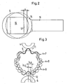
- FIG. 3 Shown in FIG. 3 are the roller 5, the roller 4 located above it, and the roller 6 located thereunder.
- the new barring pattern may have a wavelength of U / (n ⁇ 1). But until such a new barring pattern is so pronounced that it bothers, some time passes.
Description
Die Erfindung betrifft ein Verfahren zum Betreiben eines Kalanders mit einem Walzenstapel, der zwei Endwalzen und dazwischen mehrere Mittelwalzen aufweist, die in einer Pressenrichtung aneinander anliegen, wobei mindestens eine Walze durch eine weiche Walze mit einer elastischen Oberfläche gebildet ist.The invention relates to a method of operating a calender with a roll stack comprising two end rolls and, between them, a plurality of center rolls abutting one another in a press direction, at least one roll being formed by a soft roll having an elastic surface.
Derartige Kalander werden insbesondere zum Satinieren von Papier- oder Kartonbahnen verwendet. Die Erfindung wird im folgenden anhand der Behandlung einer Papierbahn beschrieben. Sie ist aber in gleicher Weise bei anderen Materialbahnen anwendbar, bei denen ähnliche Probleme auftreten.Such calenders are used in particular for calendering paper or board webs. The invention will be described below with reference to the treatment of a paper web. However, it is equally applicable to other webs where similar problems occur.
Beim Satinieren einer Papierbahn wird die Papierbahn durch den Kalander geleitet und in Nips, die zwischen einer harten und einer weichen Walze, d.h. einer Walze mit elastischer Oberfläche, gebildet sind, mit erhöhtem Druck und gegebenenfalls auch mit erhöhter Temperatur beaufschlagt. Bei Kalandern neuerer Bauart, beispielsweise den "Janus-Kalandern", kommen Walzen zum Einsatz, die mit einem Kunststoffbelag bezogen sind. Man kann nun beobachten, daß es in vielen Fällen nach einer gewissen Betriebszeit zu Querstreifen auf der Papierbahn kommt. Sobald diese Streifen sichtbar werden, ist die Papierbahn unbrauchbar und bildet Ausschuß. Die Ursachen dieser sogenannten Barring-Bildung sind derzeit noch nicht restlos geklärt. Man nimmt aber an, daß es sich hierbei um Auswirkungen einer Schwingungserscheinung handelt. Schwingungen sind in einem Kalander aber praktisch unvermeidbar.When satinizing a paper web, the paper web is passed through the calender and into nips between a hard and a soft roll, ie a roll are formed with elastic surface, subjected to elevated pressure and optionally also with elevated temperature. In calenders newer design, for example, the "Janus calenders" rollers are used, which are covered with a plastic covering. It can now be observed that in many cases, after a certain period of operation, horizontal stripes occur on the paper web. Once these streaks become visible, the paper web is useless and forms reject. The causes of this so-called barring formation are currently not fully understood. But it is believed that these are effects of a vibrational phenomenon. Vibrations are virtually unavoidable in a calender.
Bei der Barring-Bildung wird die weiche Walze verändert und zwar an ihrer elastischen Oberfläche. Es ist noch nicht abschließend geklärt, wie diese Veränderung genau aussieht. Man nimmt derzeit folgende Möglichkeiten an: Die Walze bekommt eine Welligkeit an der Oberfläche, d.h. eine Berg- und Talstruktur, die Walze wird vielekkig oder die Walze bekommt in Umfangsrichtung abwechselnd Zonen unterschiedlicher Oberflächengüte, beispielsweise unterschiedlicher Rauhigkeit. Unabhängig von der konkreten Art der Veränderung zeigen sich nach der Barring-Bildung periodische, in Axialrichtung verlaufende Streifen am Umfang der Walze. Entsprechende Streifen zeigen sich dann an der Papierbahn, wobei spätestens ab dem Sichtbarwerden der Streifen die Papierbahn als Ausschuß zu betrachten ist.In barring formation, the soft roll is changed on its elastic surface. It has not yet been clarified how this change looks exactly. Currently, the following possibilities are assumed: The roller gets a waviness at the surface, i. a mountain and valley structure, the roller becomes vielekkig or the roller gets in the circumferential direction alternately zones of different surface quality, for example, different roughness. Regardless of the specific type of change, the barring formation shows periodic, axially extending strips on the circumference of the roll. Corresponding strips then show up on the paper web, wherein at the latest from the becoming visible of the strip, the paper web is to be considered as a committee.
Wenn eine Barring-Erscheinung auftritt, muß die Walze, die die Barring-Bildung verursacht, ausgebaut und überschliffen oder abgedreht werden. Die Standzeit einer derartigen weichen Walze ist also begrenzt.If a barring phenomenon occurs, the roller that causes the barring formation must be removed and ground or turned off. The life of such a soft roll is therefore limited.
Die Erscheinung des Barrings ist auch von Glättwerken bekannt, also von Kalandern, die ausschließlich aus harten Walzen gebildet sind. Allerdings dauerte die Ausbildung des Barrings auf der Papierbahn wesentlich länger. Man nimmt an, daß die Barring-Bildung auf andere Ursachen zurückzuführen ist, insbesondere Störungen in der Papierbahn.The appearance of the barring is also known from calenders, that is calenders, which are formed exclusively of hard rollers. However, the formation of the bar ring on the paper web took much longer. It is believed that the barring formation is due to other causes, in particular disturbances in the paper web.
In "Calender Vibration - A Simulation Study and a Cure", Tappi Journal, Vol. 52, No. 7, July 1969, Seiten 1356 bis 1361, wird vorgeschlagen, eine Leitwalze so auszugestalten, daß ihre Position relativ zum Walzenstapel veränderbar ist. Damit soll eine Durchmesserveränderung einer Walze simuliert werden.In "Calender Vibration - A Simulation Study and a Cure", Tappi Journal, Vol. 52, no. 7, July 1969, pages 1356 to 1361, it is proposed to design a guide roller so that its position is variable relative to the roll stack. This is intended to simulate a diameter change of a roll.
"Calender barring on paper machines - practical conclusions and recommendations", Tappi Journal, Vol. 58, No. 8, August 1975, Seiten 147 bis 151, geht von einer ähnlichen Lösung aus, wobei alternativ vorgeschlagen wird, die Walzen zwischen 20 und 60 mm relativ zum Walzenstapel zu versetzen. Dieser Versatz hat allerdings den Nachteil, daß er die Geometrie des Walzenstapels relativ stark ändert, was sich negativ auf die Strekkenlasten und die Streckenlastverteilungen in den einzelnen Nips auswirken kann."Calender barring on paper machines - practical conclusions and recommendations", Tappi Journal, Vol. 8, August 1975, pages 147-151, starts from a similar solution, alternatively proposing to offset the rolls between 20 and 60 mm relative to the roll stack. However, this offset has the disadvantage that it changes the geometry of the roll stack relatively strong, which can adversely affect the Strekkenlasten and the line load distributions in the individual nips.
In EP 0 949 378 A1 werden Schwingungen, die über einen längeren Zeitraum auftreten, als Ursache für die Barringbildung angeführt. Ein stationärer Betrieb wird durch eine Veränderung der Antriebsmomentenverteilung bei mindestens zwei angetriebenen Wellen oder durch unterschiedliche Durchlaufgeschwindigkeiten vermieden. Dadurch werden Barringerscheinungen vermindert und die Lebensdauer weicher Walzen erhöht.In EP 0 949 378 A1, vibrations which occur over a relatively long period of time are cited as the cause of barring. Stationary operation is by a change in the drive torque distribution avoided at least two driven shafts or by different throughput speeds. As a result, Barringerscheinungen be reduced and increases the life of soft rolls.
In US 3 044 392 wird die Barringbildung auf horizontale Schwingungen (quer zur Pressenrichtung) der übereinander angeordneten Walzen zurückgeführt. Diese Schwingungen können dadurch vermieden werden, daß die horizontalen Kräfte, die durch das Führen der Papierbahn eingebracht werden, neutralisiert werden. Dies wird dadurch erreicht, daß die Achsen der Walzen horizontal zueinander statisch versetzt werden. Werden mehrere Walzen angetrieben, kann durch das Einbringen zusätzlicher Antriebsmomente die Schwingungsneigung weiter verringert werden.In US 3 044 392 the barring is attributed to horizontal oscillations (transverse to the press direction) of the superposed rolls. These vibrations can be avoided by neutralizing the horizontal forces introduced by guiding the paper web. This is achieved by staggering the axes of the rolls horizontally. If several rollers are driven, the oscillation tendency can be further reduced by introducing additional drive torques.
Mit dem Einsatz von kunststoffbezogenen Walzen ist eine neue Art von Barring entstanden, bei dem sich in relativ kurzer Zeit Muster auf der Oberfläche der weichen Walzen einprägen.With the use of plastic-based rollers, a new type of barring has emerged in which patterns are imprinted on the surface of the soft rolls in a relatively short time.
Der Erfindung liegt die Aufgabe zugrunde, die Standzeit einer weichen Walze zu erhöhen.The invention has for its object to increase the service life of a soft roll.
Diese Aufgabe wird bei einem Verfahren der eingangs genannten Art dadurch gelöst, daß man bei Auftreten eines Barring-Müsters am Umfang der weichen Walze eine Wellenlänge des Barring-Musters ermittelt und in Abhängigkeit von dieser Wellenlänge einen Walzenversatz einer weichen Walze quer zur Pressenrichtung vornimmt.This object is achieved in a method of the type mentioned above in that one determines a wavelength of the barring pattern on occurrence of a barring mousse on the circumference of the soft roll and makes a roll offset of a soft roll transversely to the press direction in response to this wavelength.
In der Regel läßt sich ein Barring-Muster auf der Oberfläche einer Walze schon feststellen, bevor sich dieses Barring-Muster in Form von Querstreifen in die Papierbahn einprägt. Wenn man also rechtzeitig Maßnahmen ergreift, um die stärkere Ausprägung des Barring-Musters zu stören, dann läßt sich die Standzeit der Walze erhöhen. Hierbei geht man von folgenden Überlegungen aus:As a rule, a barring pattern on the surface of a roller can already be established before this barring pattern impresses itself in the form of transverse strips in the paper web. So if you take measures in good time to disrupt the stronger character of the barring pattern, then you can increase the service life of the roller. This is based on the following considerations:
Ein Walzenstapel, der aus mehreren Walzen gebildet ist, hat eine Vielzahl von Eigenfrequenzen. Hierbei sind nicht die Eigenfrequenzen der einzelnen Walzen für sich, wie etwa Biegeeigenfrequenzen, gemeint, sondern die Eigenschwingungsformen, die sich aus den schwingenden Walzenmassen auf den Feder- und Dämpfersystemen der dazwischengeschalteten Kunststoffbeläge der "weichen" Walzen ergeben. Ein laufender Kalander erzeugt Erregerkräfte, deren Frequenzen sich aus dem Vielfachen der Walzendrehzahlen zusammensetzen. Diese Erregerkräfte können in Inhomogenitäten, Anisotropien oder Geometriefehlern (Unrundheiten) begründet sein. Ebenfalls können Papierdickenschwankungen der den Kalander durchlaufenden Papierbahn den Walzenstapel anregen. Eine in den Kalander einlaufende Papierbahn ist vor dem Glättprozeß noch sehr rauh. Zudem ist eine Papierbahn nie frei von Flächengewichts- bzw. Dickenschwankungen. Analysiert man diese Schwankungen mit Hilfe einer FFT-Analyse auf ihre Frequenzen, so stellt man in der Regel ein breitbandiges Rauschen fest, in dem sämtliche Frequenzen enthalten sind. Trifft eine dieser Erregerfrequenzen auf eine Eigenfrequenz, so antwortet das Schwingungssystem des Kalanders mit vergrößerten Schwingungsausschlägen. Aufgrund der Vielzahl der möglichen Erreger und der Vielzahl der möglichen Eigenschwingungsformen lassen sich diese Resonanzstellen konstruktiv nicht umgehen. In der Regel ist das Schwingungssystem auch so stark gedämpft und die Erregerkräfte sind so klein, daß die resultierenden Schwingbewegungen unmittelbar nicht störend sind. Über einen mehr oder weniger langen Zeitraum prägen sich diese Schwingbewegungen jedoch in die Kunststoffbeläge der elastischen Walzen ein.A stack of rolls, which is formed from a plurality of rolls, has a multiplicity of natural frequencies. This does not mean the natural frequencies of the individual rolls per se, such as bending natural frequencies, but the natural vibration modes which result from the oscillating roll masses on the spring and damper systems of the interposed plastic linings of the "soft" rolls. A running calender generates exciter forces whose frequencies are composed of multiples of the rolling speeds. These excitation forces can be due to inhomogeneities, anisotropies or geometrical errors (roundness). Also, paper thickness variations of the calender passing through the paper web can stimulate the roll stack. A paper web entering the calender is in front of the smoothing process still very rough. In addition, a paper web is never free of basis weight or thickness variations. If one analyzes these fluctuations with the aid of an FFT analysis on their frequencies, one usually detects a broadband noise in which all frequencies are contained. If one of these excitation frequencies hits a natural frequency, then the vibration system of the calender responds with increased oscillations. Due to the large number of possible pathogens and the large number of possible natural modes of vibration, these resonance points can not be avoided constructively. In general, the vibration system is so strongly damped and the excitation forces are so small that the resulting oscillatory movements are not directly disturbing. Over a more or less long period of time, however, these oscillatory movements are reflected in the plastic coverings of the elastic rollers.
Üblicherweise werden die zur Eigenfrequenz nächstliegenden ganzzahligen Vielfachen der Walzendrehfrequenz als Muster auf den Walzen eingeprägt. Hierdurch erfolgt eine Rückkopplung der Schwingung. Die Schwingungsausschläge nehmen dann exponentiell zu. Sie äußern sich einerseits in einem erhöhten Schallpegel (bis mehr als 120 dB(A)) und andererseits in periodischen Dickenschwankungen der durchlaufenden Papierbahn. In der Praxis werden unterschiedliche Zeiträume beobachtet, in denen sich diese Rückkopplungserscheinungen, die sich in Barrings äußern, ausbilden. Meist vergehen einige Tage oder Wochen, bis diese Erscheinung so stark angewachsen ist, daß sie den Produktionsprozeß stört.Usually, the closest to the natural frequency integer multiples of the rolling rotational frequency are impressed as a pattern on the rollers. This results in a feedback of the oscillation. The oscillations then increase exponentially. They express themselves on the one hand in an increased sound level (up to more than 120 dB (A)) and on the other hand in periodic thickness variations of the continuous paper web. In practice, different periods of time are observed in which these feedback phenomena manifest themselves in barrings. Most days or weeks pass before this phenomenon has grown so strongly that it disturbs the production process.
Wenn man nun die Barring-Muster auf der Oberfläche der Walze analysiert, stellt man fest, daß es sich hierbei um ein Wellenmuster handelt, bei dem die Wellenlänge ein ganzzahliger Bruchteil des Walzenumfanges ist. Man kann nun diese Information auswerten und die Walze quer zur Pressenrichtung um einen Betrag versetzen, in den diese Wellenlängeninformation einfließt. Da man gezielt die Wellenlängeninformation verwendet, kann der Versatz der Walze dann wieder für einige Zeit konstant gehalten werden. Ein Versatz ist daher nur in größeren Abständen erforderlich. Man kann nun den Kalander betreiben, bis sich ein Barring-Muster an der Oberfläche so stark ausgebildet hat, daß Störungen in absehbarer Zeit zu befürchten sind. Das Auftreten eines derartigen Barring-Musters läßt sich beispielsweise durch Vibrations- oder Schwingungsmessungen an dem Kalander oder sogar an jeder einzelnen Walze feststellen. Wenn man dann den Walzenversatz zu einem Zeitpunkt vornimmt, der kurz vor einem "kritischen" Zeitpunkt liegt, an dem die Walze eigentlich ausgetauscht werden müßte, dann kann man erreichen, daß sich das Barring-Muster umprägt oder sogar ganz verschwindet, so daß man die Standzeit der Walze durch einen einmaligen Versatzvorgang fast verdoppeln, in der Regel aber um mindestens 30 % verlängern kann.If one analyzes the barring patterns on the surface of the roll, one finds that this is a wave pattern in which the wavelength is an integer fraction of the roll circumference. It is now possible to evaluate this information and move the roller across the press direction by an amount into which this wavelength information flows. Since one uses the wavelength information selectively, the offset of the roller can then be kept constant again for some time. An offset is therefore required only at longer intervals. It is now possible to operate the calender until a barring pattern on the surface has developed so strongly that disturbances are to be feared in the foreseeable future. The occurrence of such a barring pattern can be determined, for example, by vibration or vibration measurements on the calender or even on each individual roller. If you then makes the roller offset at a time that is just before a "critical" time at which the roller should actually be replaced, then you can achieve that the barring pattern re-embossed or even completely disappears, so that the The life of the roller almost double by a single offset operation, but can usually extend by at least 30%.
Vorzugsweise nimmt man einen Walzenversatz vor, der kleiner als die Wellenlänge ist. Diese Vorgehensweise hat mehrere Vorteile. Zum einen wird die Versatzbewegung begrenzt, d.h. Störungen, die sich durch eine Entfernung der Walze aus der Walzenebene des Kalanders ergeben, werden klein gehalten. Zum anderen sind die baulichen oder handhabungsmäßigen Maßnahmen, die man für den Walzenversatz treffen muß, begrenzt. Im Grunde genommen könnte man den Walzenversatz theoretisch auch um ganzzahlige Vielfache der Wellenlängen vergrößern. Die Beschränkung auf die kleinstmögliche Strecke bringt aber die obengenannten Vorteile.Preferably, one takes a roll offset, which is smaller than the wavelength. This procedure has several advantages. On the one hand, the displacement movement is limited, ie disturbances that result from removal of the roll from the rolling plane of the calender are kept small. On the other hand, the structural or handling measures that must be taken for the roller offset, limited. Essentially could theoretically increase the roll offset by integer multiples of the wavelengths. The restriction to the smallest possible distance but brings the above advantages.
Bevorzugterweise nimmt man einen Walzenversatz an der Walze vor, an der das Barring-Muster auftritt. Damit beseitigt man die Störung unmittelbar am Ort der Entstehung. Insbesondere bei Mittelwalzen kann man dann zwei Nips für die Beseitigung der Barring-Muster verwenden.Preferably, a roll offset is made on the roll at which the barring pattern occurs. This eliminates the disturbance immediately at the place of origin. Especially with center rolls you can then use two nips for the elimination of the barring pattern.
Bevorzugterweise ist vorgesehen, daß man einen Walzenversatz vornimmt, der auf der Oberfläche der Walze einen Wellenlängenunterschied von einer halben Länge in einem ersten Fall und von einer viertel Wellenlänge in einem zweiten Fall bewirkt, wobei im ersten Fall ein Barring-Muster an der Oberfläche der Walze aufgetreten ist, das beseitigt werden soll, und im zweiten Fall eine Beseitigung nicht erforderlich ist. Bei dieser Vorgehensweise geht man davon aus, daß das Barring-Muster an der Oberfläche der Walze durch eine Schwingung entstanden ist, bei der die Nachbarwalze bzw. die Nachbarwalzen immer an bestimmten Punkten am Umfang der Walze eine starke Belastung auf die Walze ausüben und an anderen Punkten, die um eine halbe Wellenlänge dazu versetzt sind, eine weniger starke Belastung. Mittelwalzen, bei denen die Ausbildung derartiger Barring-Muster besonders häufig zu beobachten ist, werden darüber hinaus durch das Zusammenwirken beider Nachbarwalzen belastet. Wenn man nun den Weg auf der Walzenoberfläche zwischen zwei Nips um eine halbe Wellenlänge verändert, also um eine halbe Wellenlänge verlängert oder verkürzt, dann werden sich bei ansonsten unveränderten Bedingungen die "Wellenberge" immer am Ort der höchsten Belastung und die "Wellentäler" am Ort der niedrigsten Belastung befinden. Das Barring-Muster wird sich auf diese Art und Weise relativ schnell umprägen. Man nimmt damit zwar in Kauf, daß sich ein neues Barring-Muster bildet. Die Zeit, die zum Verschwinden des "alten" Barring-Musters erforderlich ist und die Zeit, die zur Ausbildung des "neuen" Barring-Musters verwendet wird, verlängert jedoch die Standzeit der Walze. Wenn eine Beseitigung des Barring-Musters (noch) nicht erforderlich ist, dann kann man auch vorsehen, daß man den Weg auf der Walzenoberfläche zwischen zwei Nips nur um eine viertel Wellenlänge verändert. Wenn sich zuvor Barring-Muster gebildet haben, die ein tolerierbares Maß noch nicht überschritten haben, dann ist eine Beseitigung von Barring-Mustern vielfach gar nicht erforderlich.Preferably, it is provided that a roller displacement is performed, which causes on the surface of the roller a wavelength difference of half a length in a first case and a quarter wavelength in a second case, in the first case, a barring pattern on the surface of the roller occurred, which is to be eliminated, and in the second case, an elimination is not required. In this approach, it is assumed that the barring pattern has formed on the surface of the roll by a vibration in which the adjacent roll or the adjacent rolls always exert a strong load on the roll at certain points on the circumference of the roll and at others Points that are offset by half a wavelength to a less intense load. Center rollers, in which the formation of such barring pattern is observed particularly frequently, are also burdened by the interaction of both neighboring rollers. If you now change the path on the roll surface between two nips by half a wavelength, ie extended or shortened by half a wavelength, then, with otherwise unchanged conditions, the "wave crests" will always be at the place of highest load and the "wave troughs" will be at the place of lowest load. The barring pattern will re-emboss relatively quickly in this way. It is indeed accepted that forms a new Barring pattern. However, the time required for the "old" barring pattern to disappear and the time spent to form the "new" barring pattern increases the life of the roll. If elimination of the barring pattern is not (yet) required, then one can also provide for changing the path on the roll surface between two nips by only a quarter wavelength. If previously barring patterns have formed that have not yet exceeded a tolerable level, eliminating barring patterns is often unnecessary.
Vorzugsweise nimmt man einen Walzenversatz um die Hälfte des Weglängenunterschieds vor, wenn es sich bei der Walze um eine Mittelwalze handelt. Der Weglängenunterschied ist im Grunde genommen der Laufzeitunterschied zwischen zwei Nips. Wenn man nun jedem dieser beiden Nips die Hälfte des Weglängenunterschiedes zurechnet, dann reicht es aus, die Walze insgesamt um die Hälfte dieses Weglängenunterschiedes zu versetzen. Damit werden Versatzbewegungen der Walze außerordentlich klein gehalten. Man muß den Versatz zwar relativ genau vornehmen. Dies ist aber, wie weiter unten beschrieben werden wird, problemlos möglich.Preferably, roll offset is effected by half the path length difference when the roll is a center roll. The path length difference is basically the transit time difference between two nips. If one adds each of these two nips half of the path length difference, then it is sufficient to offset the roller altogether by half of this path length difference. This offset movements of the roller are kept extremely small. It is necessary to make the offset relatively accurately. However, this is easily possible, as will be described below.
Vorzugsweise stellt man einen Weglängenunterschied von einer viertel Wellenlänge beim Austausch einer Walze gegen eine baugleiche Ersatzwalze ein. Bei einer baugleichen Ersatzwalze ist davon auszugehen, daß die gleichen Schwingungserscheinungen auftreten. Da bei einer Ersatzwalze aber noch kein Barring-Muster entstanden ist, ist eine Beseitigung auch nicht erforderlich. Man kann daher eine "Prävention" treffen und durch Versatz der Walze gegenüber einer Situation, in der sich Barring-Muster gebildet haben, dafür sorgen, daß sich das Barring-Muster eben nicht bildet. Man ist bei dieser Vorgehensweise zwar nicht davor gesichert, daß sich ein anderes Barring-Muster bildet. Die Wahrscheinlichkeit dafür ist jedoch verringert. Falls sich ein anderes Barring-Muster bildet, kann man dieses wieder mit den oben beschriebenen Maßnahmen beseitigen. Die Standzeit der Walze wird auf jeden Fall erhöht.Preferably, one makes a path length difference of a quarter wavelength when replacing a roller against a structurally identical replacement roller. With an identical replacement roller, it can be assumed that the same vibration phenomena occur. Since a spare roll but no barring pattern has emerged, a removal is not required. One can therefore take a "prevention" and by offsetting the roller against a situation in which barring patterns have formed, ensure that the barring pattern just does not form. Although this procedure does not ensure that another barring pattern is formed. The likelihood is reduced. If another barring pattern is formed, this can be remedied again with the measures described above. The life of the roller is increased in any case.
Bevorzugterweise nimmt man den Walzenversatz durch Längenänderung eines Hebels vor, an dem die Walze gelagert ist. Dies ist eine relativ einfache Maßnahme, um die Walze zu verlagern. Die Walze kann dann wieder für einige Zeit fest an der Position verbleiben, die durch die Längenänderung des Hebels festgelegt worden ist.Preferably, the roll offset is achieved by changing the length of a lever on which the roll is mounted. This is a relatively simple measure to relocate the roller. The roller may then again remain firmly in position for some time, which has been determined by the change in length of the lever.
Hierbei ist besonders bevorzugt, daß man ein Distanzstück zwischen Walzenlager und Hebel einsetzt. Dieses Distanzstück kann relativ genau auf die Wellenlänge angepaßt werden. Durch Wahl eines geeigneten Distanzstükkes läßt sich dann der entsprechende Versatz mit ausreichender Genauigkeit bewirken.It is particularly preferred that one uses a spacer between roller bearing and lever. This spacer can be adapted relatively accurately to the wavelength. By choosing a suitable Distanzstükkes can then cause the corresponding offset with sufficient accuracy.
Die Erfindung wird im folgenden anhand eines bevorzugten Ausführungsbeispiels in Verbindung mit der Zeichnung näher beschrieben. Hierin zeigen:
- Fig. 1
- eine schematische Darstellung eines Kalanders,
- Fig. 2
- eine Möglichkeit zur Einstellung des Versatzes und
- Fig. 3
- eine schematische Darstellung zur Erläuterung der Ausbildung eines Barring-Musters.
- Fig. 1
- a schematic representation of a calender,
- Fig. 2
- a way to adjust the offset and
- Fig. 3
- a schematic representation for explaining the formation of a barring pattern.
Fig. 1 zeigt schematisch einen Kalander 1 mit zwei Endwalzen 2, 3, die als Durchbiegungswalzen ausgebildet sind, und drei Mittelwalzen 4 - 6, die zusammen einen Walzenstapel bilden. Der Walzenstapel weist eine Walzenebene 7 auf, in der die Achsen aller Walzen 2 - 6 liegen, wenn die Walzen 2 - 6 exakt übereinander angeordnet sind. In dieser Walzenebene 7 liegt für die Zwecke der nachfolgenden Beschreibung auch die Pressenrichtung, d.h. die Richtung, in der die Walzen 2 - 6 gegeneinander gedrückt werden.Fig. 1 shows schematically a calender 1 with two end rolls 2, 3, which are formed as deflection rolls, and three center rolls 4 - 6, which together form a roll stack. The roll stack has a
Weitere Einzelheiten des Kalanders sind nur schematisch dargestellt, wie ein Antrieb 8, oder ganz weggelassen, wie Mittel zur Beheizung von einzelnen Walzen. Die beiden Endwalzen 2, 3 und die mittlerste Walze 5 weisen aber einen elastischen Belag 9 auf, der übertrieben dick dargestellt ist.Further details of the calender are shown only schematically, such as a
Die Walzen 2 - 6 bilden beim Betrieb des Kalanders in bekannter Weise Nips 10 - 13, durch die eine zu behandelnde Materialbahn geführt wird. Alle Nips sind hier als sogenannte weiche Nips ausgebildet, da sie von einer harten und von einer weichen Walze begrenzt werden.The rollers 2 - 6 form during operation of the calender in a known manner nips 10 - 13, through which a material web to be treated is guided. All nips are here designed as so-called soft nips, as they are bounded by a hard and a soft roller.
Im Betrieb kann man nun beobachten, daß sich auf den weichen Walzen Oberflächenmuster ausbilden, die sich, wenn sie eine kritische Größe überschritten haben, in die Papierbahn einprägen. Um ein derartiges Barring-Muster zu vermeiden oder ein bereits entstandenes Barring-Muster zurückzubilden, ist nun vorgesehen, daß man die betreffende Walze, im vorliegenden Fall die mittlere Walze 5, um eine Strecke X gegenüber der Walzenebene 7 versetzt. Die Vorgehensweise hierfür soll im Zusammenhang mit Fig. 2 erläutert werden.In operation, it can now be observed that surface patterns form on the soft rolls which, when they have exceeded a critical size, are impressed into the paper web. In order to avoid such a barring pattern or to rebuild an existing barring pattern, it is now provided that the respective roller, in the present case the
Die Walze 5 ist an einem Hebel 14 gelagert, der in einer nicht näher dargestellten Stuhlung des Kalanders gelenkig aufgehängt ist. Hierbei weist die Walze 5 ein Lagergehäuse 15 auf, das an einer Lagerfläche 16 des Hebels 14 festgeschraubt oder auf andere Weise befestigt werden kann. In diesem Fall befindet sich die Walze 5 in der gestrichelt dargestellten Position. Wenn man nun feststellt, daß sich in dieser Position ein Barring-Muster an der Oberfläche ausbildet, dann wird die Walze 5 um die Entfernung X versetzt, indem zwischen die Lagerfläche und das Lagergehäuse 15 ein Distanzstück 17 eingeschoben wird. Hierzu wird das Lagergehäuse 15 von der Lagerfläche 16 gelöst, das Distanzstück 17 eingeschoben und das Lagergehäuse 15 wieder am Hebel 14 befestigt. Die Dicke des Distanzstücks 17 ist dann die Entfernung X. Diese Entfernung X kann mit einer relativ großen Genauigkeit eingestellt werden. Die Ermittlung dieser Entfernung X wird anhand von Fig. 3 erläutert.The
In Fig. 3 dargestellt sind die Walze 5, die darüber befindliche Walze 4 und die darunter befindliche Walze 6.Shown in FIG. 3 are the
Mit übertrieben großen Amplituden sind verschiedene Bezugswelligkeiten dargestellt und zwar eine Welligkeit, bei der sieben Wellen um den Umfang der Walze 5 herumlaufen, eine mit acht Wellen und eine mit neun Wellen. Die Anzahlen n = 7, 8, 9 wurden aus Gründen der Übersicht gewählt. Bei realen Walzen werden sich über den Umfang der Walze entsprechend mehr Wellen einstellen, beispielsweise in der Größenordnung von 30 bis 50. Bei derart vielen Wellen, die um den Umfang der Walze 5 verlaufen, kann man in erster Näherung davon ausgehen, daß bei einer kleinen Versatzbewegung der Walze 5 gegenüber der Walzenebene 7, die kleiner ist als eine Wellenlänge, die Krümmung der Walze 5 keine Rolle spielt.With excessively large amplitudes different reference ripples are shown, namely a ripple, in which seven waves run around the circumference of the
Wenn ein Barring-Muster mit einer Wellenlänge λ aufgetreten ist, versetzt man nun die Walze 5 gegenüber der Walzenebene 7, d.h. gegenüber den Nips 11, 12 so, daß die Entfernung zwischen den beiden Nips 11, 12 auf der einen Seite um eine halbe Wellenlänge λ/2 vergrößert und auf der anderen Seite um diese halbe Wellenlänge λ/2 verkleinert wird. Hierzu ist lediglich ein Versatz X erforderlich, der X = λ/4 entspricht, weil sich dadurch der gewünschte Weglängenunterschied zwischen den beiden Nips 11, 12 ergibt.When a barring pattern having a wavelength λ has occurred, the
Bei einem Weglängenunterschied von λ/2 entsteht an den Punkten des Umfangs der Walze 5, die zuvor stark belastet worden sind und wo sich dementsprechend Wellentäler ausgebildet haben, keine Belastung. Diese Belastung entsteht vielmehr an den Wellenbergen, an denen bisher die entsprechende Belastung gefehlt hat. Die Belastungen ergeben sich durch die Schwingungsbewegungen der drei Walzen 4, 5, 6 relativ zueinander. Man kann durch einen Weglängenunterschied von λ/2 also erreichen, daß sich ein bereits ausgebildetes Barring-Muster wieder umprägt und im Laufe der Zeit verschwindet. Man riskiert dabei zwar, daß sich ein anderes Barring-Muster ausbildet, dessen Wellenlänge in der Nähe der Wellenlänge des ursprünglichen Barring-Musters liegt. Wenn also das ursprüngliche Barring-Muster eine Wellenlänge U/n hatte, wobei U der Umfang der Walze 5 ist, dann hat das neue Barring-Muster möglicherweise eine Wellenlänge von U/(n ± 1). Bis ein derartiges neues Barring-Muster aber so weit ausgeprägt ist, daß es stört, vergeht einige Zeit.With a path length difference of λ / 2 arises at the points of the circumference of the
Wenn das Barring-Muster noch nicht so weit ausgeprägt ist, daß es stört, oder wenn man eine Ersatzwalze verwendet, die baugleich mit der ursprünglichen Walze ist, an der sich das Barring-Muster gezeigt hat, dann kann man auch einen Walzenversatz X wählen, der genau halb so groß ist, nämlich X = λ/8 beträgt. In diesem Fall wird der Weglängenunterschied um den Betrag λ/4 verändert. Bei diesem Weglängenunterschied wird sich das bislang erzeugte Barring-Muster nicht weiter vergrößern bzw. es wird sich kein neues Barring-Muster mit dieser Wellenlänge ausbilden.If the barring pattern is not yet so pronounced that it bothers, or if one uses a replacement roll that is identical to the original roll on which the barring pattern has been shown, then one can also choose a roll offset X, which is exactly half the size, namely X = λ / 8. In this case, the path length difference is changed by the amount λ / 4. In the case of this path length difference, the previously generated barring pattern will not increase further, or no new barring pattern with this wavelength will be formed.
Durch den statischen Walzenversatz, der eine Wegverlängerung zwischen den beiden Nips 11, 12 von einer viertel Wellenlänge λ/4 bewirkt, ist davon auszugehen, daß sich bei der gleichen Erregung durch die Kopplung mit den beiden Nachbarwalzen die Störungen getrennt voneinander mit halber Intensität einprägen, so daß theoretisch eine Verdoppelung der Standzeit zu erzielen ist.Due to the static roller displacement, which causes a path extension between the two
In der Praxis wird es in der Regel nicht zu erreichen sein, daß Walzen in allen Parametern tatsächlich identisch sind, auch wenn eine Ersatzwalze baugleich mit der auszutauschenden Walze ist. Dennoch kann man davon ausgehen, daß man durch einen statischen Walzenversatz, der sich an der Wellenlänge des Barring-Musters auf der Oberfläche der auszutauschenden Walze orientiert, eine Verlängerung der Standzeit der Ersatzwalze erreichen kann, wenn man beispielsweise die Ersatzwalze um eine achtel Wellenlänge λ/8 zur Walzenebene 7 versetzt, so daß sich die Strecke zwischen den beiden Nips um λ/4 auf der einen Seite vergrößert und auf der anderen Seite verkleinert. Auch wenn die Ersatzwalze dann nicht mit exakt der gleichen Antwort auf die Schwingungen des Kalanders reagiert, kann man von einer Verlängerung der Standzeit gegenüber einem einfachen Austausch ohne eine derartige Maßnahme ausgehen.In practice, it will usually not be possible to achieve that rolls are actually identical in all parameters, even if a replacement roll is identical in construction to the roll to be replaced. Nevertheless, it can be assumed that a prolonged service life of the replacement roller can be achieved by a static roller offset, which is based on the wavelength of the barring pattern on the surface of the roller to be replaced, if, for example, the replacement roller is shifted by one-eighth wavelength λ /. 8 offset to the
Claims (8)
- Process for operating a calender having a roll stack which has two end rolls and a plurality of intermediate rolls between them, which bear on one another in a pressing direction, at least one roll being formed by a soft roll having a resilient surface, characterized in that, in the event of a barring pattern occurring on the circumference of the soft roll, a wavelength of the barring pattern is determined and a soft roll is offset transversely with respect to the pressing direction as a function of this wavelength.
- Process according to Claim 1, characterized in that the roll is offset by an amount which is smaller than the wavelength.
- Process according to Claim 1 or 2, characterized in that the roll on which the barring pattern occurs is offset.
- Process according to one of Claims 1 to 3,
characterized in that the roll is offset such that, on the surface of the roll, the effect is a path length difference of half a wavelength in a first case and of a quarter of a wavelength in a second case, in the first case a barring pattern having occurred on the surface of the roll and is to be eliminated and in the second case elimination not being required. - Process according to Claim 4, characterized in that the roll is offset by half the path length difference if the roll is an intermediate roll.
- Process according to Claim 4 or 5, characterized in that a path length difference of a quarter of a wavelength is set when a roll is replaced by an identical replacement roll.
- Process according to one of Claims 1 to 6,
characterized in that the roll is offset by changing the length of a lever on which the roll is mounted. - Process according to Claim 7, characterized in that a spacer is inserted between roll bearing and lever.
Applications Claiming Priority (2)
| Application Number | Priority Date | Filing Date | Title |
|---|---|---|---|
| DE10133890 | 2001-07-12 | ||
| DE10133890A DE10133890C1 (en) | 2001-07-12 | 2001-07-12 | Operation of calender roller stack to prevent striped patterning, adjusts soft roller transversely with respect to pressing direction as function of wavelength |
Publications (2)
| Publication Number | Publication Date |
|---|---|
| EP1275775A1 EP1275775A1 (en) | 2003-01-15 |
| EP1275775B1 true EP1275775B1 (en) | 2007-01-03 |
Family
ID=7691529
Family Applications (1)
| Application Number | Title | Priority Date | Filing Date |
|---|---|---|---|
| EP02014377A Expired - Fee Related EP1275775B1 (en) | 2001-07-12 | 2002-06-28 | Process for operating a calender |
Country Status (4)
| Country | Link |
|---|---|
| US (1) | US6902691B2 (en) |
| EP (1) | EP1275775B1 (en) |
| CA (1) | CA2393227A1 (en) |
| DE (2) | DE10133890C1 (en) |
Families Citing this family (3)
| Publication number | Priority date | Publication date | Assignee | Title |
|---|---|---|---|---|
| FI119851B (en) | 2007-09-28 | 2009-04-15 | Metso Paper Inc | Method for attenuating periodic vibration of a fiber web machine |
| DE102012201951A1 (en) | 2012-02-09 | 2013-08-14 | Metso Paper, Inc. | Calender has roller stack having successive rolls, and spreading rollers which are formed such that distance of fiber web between roller and nips before and after roller is equal to or integral multiples of circumference of roller |
| EP2806063A1 (en) | 2013-05-20 | 2014-11-26 | Valmet Technologies, Inc. | Method for preventing vibration of a calender and a calender with an arrangement for preventing vibration |
Family Cites Families (12)
| Publication number | Priority date | Publication date | Assignee | Title |
|---|---|---|---|---|
| US3044392A (en) * | 1959-07-10 | 1962-07-17 | Kimberly Clark Co | Papermaking machine |
| NL299751A (en) | 1962-10-26 | |||
| FI64902C (en) | 1976-03-30 | 1984-02-10 | Wiik & Hoeglund | COMPENSATION FOR COMPENSATION OF VALUES AND ENVIRONMENT |
| US4348952A (en) | 1981-01-19 | 1982-09-14 | Usm Corporation | Cross axis mechanism |
| US4516491A (en) | 1983-09-30 | 1985-05-14 | Usm Corporation | Roll cross-axis mechanism |
| DE4314653C2 (en) | 1993-05-04 | 1997-01-30 | Troester Maschf Paul | Multi-purpose calender |
| DE19601293C2 (en) | 1996-01-16 | 1999-09-16 | Voith Sulzer Finishing Gmbh | Method and device for treating a material web |
| US5961899A (en) | 1997-07-15 | 1999-10-05 | Lord Corporation | Vibration control apparatus and method for calender rolls and the like |
| EP1032731B1 (en) | 1997-11-17 | 2004-05-19 | Metso Paper, Inc. | Method for detecting contamination and/or damaging of a face that runs through a nip or nips in a calender for paper |
| DE19815339A1 (en) * | 1998-04-06 | 1999-10-14 | Voith Sulzer Papiermasch Gmbh | Rolling machine and method for its operation |
| DE19832067B4 (en) | 1998-07-16 | 2005-04-21 | Voith Paper Patent Gmbh | Calender for webs of paper or similar material |
| DE10008800B4 (en) | 2000-02-25 | 2005-10-27 | Voith Paper Patent Gmbh | Method for operating a calender roll and calender roll |
-
2001
- 2001-07-12 DE DE10133890A patent/DE10133890C1/en not_active Revoked
-
2002
- 2002-06-28 EP EP02014377A patent/EP1275775B1/en not_active Expired - Fee Related
- 2002-06-28 DE DE50209132T patent/DE50209132D1/en not_active Expired - Lifetime
- 2002-07-11 US US10/192,529 patent/US6902691B2/en not_active Expired - Fee Related
- 2002-07-11 CA CA002393227A patent/CA2393227A1/en not_active Abandoned
Also Published As
| Publication number | Publication date |
|---|---|
| DE50209132D1 (en) | 2007-02-15 |
| EP1275775A1 (en) | 2003-01-15 |
| US20030026864A1 (en) | 2003-02-06 |
| CA2393227A1 (en) | 2003-01-12 |
| US6902691B2 (en) | 2005-06-07 |
| DE10133890C1 (en) | 2002-12-05 |
Similar Documents
| Publication | Publication Date | Title |
|---|---|---|
| EP1411254B1 (en) | Middle roll of a calender with a damper assembly having an inertial mass | |
| DE3201635C2 (en) | Calender arrangement | |
| EP0949378B1 (en) | Roller machine and method of operating the same | |
| DE3815445C2 (en) | ||
| EP1275774B1 (en) | Process for operating a calender and calender | |
| EP1275775B1 (en) | Process for operating a calender | |
| EP1275776B1 (en) | Calender and method of arranging rolls in a calender stack | |
| EP1275777B1 (en) | Process for operating a calender | |
| DE19907079A1 (en) | System to counter contact oscillation in paired rollers processing a paper web has force units and tensioners within the rollers to modify their inner tension under control according to sensor measurements | |
| DE10006299B4 (en) | Method for operating a calender roll and calender roll | |
| EP1225274B1 (en) | Process for treating a web of material and calender | |
| DE102011052229A1 (en) | calender | |
| EP1531199B1 (en) | Calender | |
| DE102007047904A1 (en) | Roller arrangement for use in sheets of fibrous material, has three rollers and two roller pairs, between which two press nips are formed, through which fibrous sheet material is controlled | |
| AT505346B1 (en) | PROFILE REGULATION FOR A CALANDER | |
| EP2128337B1 (en) | Method for operating a calender and same | |
| DE10317676B3 (en) | Calender, to polish a paper/cardboard web, adjusts the friction value between the web and a roller continuously or intermittently to prevent the formation of bar effects on the web | |
| EP4347227A1 (en) | Ultrasonic processing devices having a support element | |
| DE112006004163T5 (en) | Paper machine roll and method of making this | |
| DE102008041905A1 (en) | Pressing device for wet part of material web producing machine utilized for producing e.g. paper web, has two pressing rollers, where support areas of one of rollers are adjustable towards or opposite to machine direction | |
| DE19907078A1 (en) | System to counter contact oscillation in paired rollers processing a paper or cardboard web has systems to vary their mass/mass distribution and position and speed under control according to sensor measurements | |
| DE10158910A1 (en) | Process and calender for satinizing a paper or cardboard web | |
| DE112006000227T5 (en) | Bearing assembly for a roll in a web treatment machine, and method for damping roll vibrations | |
| EP1505205A1 (en) | Device for treating a web | |
| WO2011116999A1 (en) | Sheet forming system for a machine for producing a fibrous web, and associated method |
Legal Events
| Date | Code | Title | Description |
|---|---|---|---|
| PUAI | Public reference made under article 153(3) epc to a published international application that has entered the european phase |
Free format text: ORIGINAL CODE: 0009012 |
|
| 17P | Request for examination filed |
Effective date: 20021113 |
|
| AK | Designated contracting states |
Kind code of ref document: A1 Designated state(s): AT BE CH CY DE DK ES FI FR GB GR IE IT LI LU MC NL PT SE TR |
|
| AX | Request for extension of the european patent |
Free format text: AL;LT;LV;MK;RO;SI |
|
| AKX | Designation fees paid |
Designated state(s): DE FI SE |
|
| GRAP | Despatch of communication of intention to grant a patent |
Free format text: ORIGINAL CODE: EPIDOSNIGR1 |
|
| RAP1 | Party data changed (applicant data changed or rights of an application transferred) |
Owner name: VOITH PATENT GMBH |
|
| GRAS | Grant fee paid |
Free format text: ORIGINAL CODE: EPIDOSNIGR3 |
|
| GRAA | (expected) grant |
Free format text: ORIGINAL CODE: 0009210 |
|
| AK | Designated contracting states |
Kind code of ref document: B1 Designated state(s): DE FI SE |
|
| REF | Corresponds to: |
Ref document number: 50209132 Country of ref document: DE Date of ref document: 20070215 Kind code of ref document: P |
|
| REG | Reference to a national code |
Ref country code: SE Ref legal event code: TRGR |
|
| PLBI | Opposition filed |
Free format text: ORIGINAL CODE: 0009260 |
|
| PLAX | Notice of opposition and request to file observation + time limit sent |
Free format text: ORIGINAL CODE: EPIDOSNOBS2 |
|
| 26 | Opposition filed |
Opponent name: ANDRITZ KUESTERS GMBH Effective date: 20071002 |
|
| PLBB | Reply of patent proprietor to notice(s) of opposition received |
Free format text: ORIGINAL CODE: EPIDOSNOBS3 |
|
| PLBP | Opposition withdrawn |
Free format text: ORIGINAL CODE: 0009264 |
|
| PLBD | Termination of opposition procedure: decision despatched |
Free format text: ORIGINAL CODE: EPIDOSNOPC1 |
|
| PLBM | Termination of opposition procedure: date of legal effect published |
Free format text: ORIGINAL CODE: 0009276 |
|
| STAA | Information on the status of an ep patent application or granted ep patent |
Free format text: STATUS: OPPOSITION PROCEDURE CLOSED |
|
| 27C | Opposition proceedings terminated |
Effective date: 20090530 |
|
| PGFP | Annual fee paid to national office [announced via postgrant information from national office to epo] |
Ref country code: SE Payment date: 20110613 Year of fee payment: 10 |
|
| REG | Reference to a national code |
Ref country code: SE Ref legal event code: EUG |
|
| PG25 | Lapsed in a contracting state [announced via postgrant information from national office to epo] |
Ref country code: SE Free format text: LAPSE BECAUSE OF NON-PAYMENT OF DUE FEES Effective date: 20120629 |
|
| PGFP | Annual fee paid to national office [announced via postgrant information from national office to epo] |
Ref country code: DE Payment date: 20130620 Year of fee payment: 12 |
|
| PGFP | Annual fee paid to national office [announced via postgrant information from national office to epo] |
Ref country code: FI Payment date: 20130613 Year of fee payment: 12 |
|
| REG | Reference to a national code |
Ref country code: DE Ref legal event code: R119 Ref document number: 50209132 Country of ref document: DE |
|
| PG25 | Lapsed in a contracting state [announced via postgrant information from national office to epo] |
Ref country code: FI Free format text: LAPSE BECAUSE OF NON-PAYMENT OF DUE FEES Effective date: 20140628 |
|
| REG | Reference to a national code |
Ref country code: DE Ref legal event code: R119 Ref document number: 50209132 Country of ref document: DE Effective date: 20150101 |
|
| PG25 | Lapsed in a contracting state [announced via postgrant information from national office to epo] |
Ref country code: DE Free format text: LAPSE BECAUSE OF NON-PAYMENT OF DUE FEES Effective date: 20150101 |