EP1126074B1 - Pneumatic tyre - Google Patents
Pneumatic tyre Download PDFInfo
- Publication number
- EP1126074B1 EP1126074B1 EP01301322A EP01301322A EP1126074B1 EP 1126074 B1 EP1126074 B1 EP 1126074B1 EP 01301322 A EP01301322 A EP 01301322A EP 01301322 A EP01301322 A EP 01301322A EP 1126074 B1 EP1126074 B1 EP 1126074B1
- Authority
- EP
- European Patent Office
- Prior art keywords
- filaments
- filament
- cord
- waved
- diameter
- Prior art date
- Legal status (The legal status is an assumption and is not a legal conclusion. Google has not performed a legal analysis and makes no representation as to the accuracy of the status listed.)
- Expired - Lifetime
Links
Images


Classifications
-
- D—TEXTILES; PAPER
- D07—ROPES; CABLES OTHER THAN ELECTRIC
- D07B—ROPES OR CABLES IN GENERAL
- D07B1/00—Constructional features of ropes or cables
- D07B1/06—Ropes or cables built-up from metal wires, e.g. of section wires around a hemp core
- D07B1/0606—Reinforcing cords for rubber or plastic articles
- D07B1/0613—Reinforcing cords for rubber or plastic articles the reinforcing cords being characterised by the rope configuration
-
- B—PERFORMING OPERATIONS; TRANSPORTING
- B60—VEHICLES IN GENERAL
- B60C—VEHICLE TYRES; TYRE INFLATION; TYRE CHANGING; CONNECTING VALVES TO INFLATABLE ELASTIC BODIES IN GENERAL; DEVICES OR ARRANGEMENTS RELATED TO TYRES
- B60C15/00—Tyre beads, e.g. ply turn-up or overlap
- B60C15/04—Bead cores
-
- B—PERFORMING OPERATIONS; TRANSPORTING
- B60—VEHICLES IN GENERAL
- B60C—VEHICLE TYRES; TYRE INFLATION; TYRE CHANGING; CONNECTING VALVES TO INFLATABLE ELASTIC BODIES IN GENERAL; DEVICES OR ARRANGEMENTS RELATED TO TYRES
- B60C9/00—Reinforcements or ply arrangement of pneumatic tyres
- B60C9/0007—Reinforcements made of metallic elements, e.g. cords, yarns, filaments or fibres made from metal
-
- B—PERFORMING OPERATIONS; TRANSPORTING
- B60—VEHICLES IN GENERAL
- B60C—VEHICLE TYRES; TYRE INFLATION; TYRE CHANGING; CONNECTING VALVES TO INFLATABLE ELASTIC BODIES IN GENERAL; DEVICES OR ARRANGEMENTS RELATED TO TYRES
- B60C9/00—Reinforcements or ply arrangement of pneumatic tyres
- B60C9/0057—Reinforcements comprising preshaped elements, e.g. undulated or zig-zag filaments
-
- B—PERFORMING OPERATIONS; TRANSPORTING
- B60—VEHICLES IN GENERAL
- B60C—VEHICLE TYRES; TYRE INFLATION; TYRE CHANGING; CONNECTING VALVES TO INFLATABLE ELASTIC BODIES IN GENERAL; DEVICES OR ARRANGEMENTS RELATED TO TYRES
- B60C9/00—Reinforcements or ply arrangement of pneumatic tyres
- B60C9/02—Carcasses
-
- B—PERFORMING OPERATIONS; TRANSPORTING
- B60—VEHICLES IN GENERAL
- B60C—VEHICLE TYRES; TYRE INFLATION; TYRE CHANGING; CONNECTING VALVES TO INFLATABLE ELASTIC BODIES IN GENERAL; DEVICES OR ARRANGEMENTS RELATED TO TYRES
- B60C9/00—Reinforcements or ply arrangement of pneumatic tyres
- B60C9/18—Structure or arrangement of belts or breakers, crown-reinforcing or cushioning layers
- B60C9/20—Structure or arrangement of belts or breakers, crown-reinforcing or cushioning layers built-up from rubberised plies each having all cords arranged substantially parallel
- B60C9/2003—Structure or arrangement of belts or breakers, crown-reinforcing or cushioning layers built-up from rubberised plies each having all cords arranged substantially parallel characterised by the materials of the belt cords
- B60C9/2006—Structure or arrangement of belts or breakers, crown-reinforcing or cushioning layers built-up from rubberised plies each having all cords arranged substantially parallel characterised by the materials of the belt cords consisting of steel cord plies only
-
- D—TEXTILES; PAPER
- D07—ROPES; CABLES OTHER THAN ELECTRIC
- D07B—ROPES OR CABLES IN GENERAL
- D07B1/00—Constructional features of ropes or cables
- D07B1/06—Ropes or cables built-up from metal wires, e.g. of section wires around a hemp core
- D07B1/0606—Reinforcing cords for rubber or plastic articles
- D07B1/062—Reinforcing cords for rubber or plastic articles the reinforcing cords being characterised by the strand configuration
-
- D—TEXTILES; PAPER
- D07—ROPES; CABLES OTHER THAN ELECTRIC
- D07B—ROPES OR CABLES IN GENERAL
- D07B1/00—Constructional features of ropes or cables
- D07B1/06—Ropes or cables built-up from metal wires, e.g. of section wires around a hemp core
- D07B1/0606—Reinforcing cords for rubber or plastic articles
- D07B1/0646—Reinforcing cords for rubber or plastic articles comprising longitudinally preformed wires
-
- B—PERFORMING OPERATIONS; TRANSPORTING
- B60—VEHICLES IN GENERAL
- B60C—VEHICLE TYRES; TYRE INFLATION; TYRE CHANGING; CONNECTING VALVES TO INFLATABLE ELASTIC BODIES IN GENERAL; DEVICES OR ARRANGEMENTS RELATED TO TYRES
- B60C9/00—Reinforcements or ply arrangement of pneumatic tyres
- B60C9/02—Carcasses
- B60C9/04—Carcasses the reinforcing cords of each carcass ply arranged in a substantially parallel relationship
- B60C2009/0416—Physical properties or dimensions of the carcass cords
- B60C2009/0425—Diameters of the cords; Linear density thereof
-
- D—TEXTILES; PAPER
- D07—ROPES; CABLES OTHER THAN ELECTRIC
- D07B—ROPES OR CABLES IN GENERAL
- D07B2201/00—Ropes or cables
- D07B2201/10—Rope or cable structures
- D07B2201/1012—Rope or cable structures characterised by their internal structure
- D07B2201/102—Rope or cable structures characterised by their internal structure including a core
-
- D—TEXTILES; PAPER
- D07—ROPES; CABLES OTHER THAN ELECTRIC
- D07B—ROPES OR CABLES IN GENERAL
- D07B2201/00—Ropes or cables
- D07B2201/10—Rope or cable structures
- D07B2201/1028—Rope or cable structures characterised by the number of strands
- D07B2201/1032—Rope or cable structures characterised by the number of strands three to eight strands respectively forming a single layer
-
- D—TEXTILES; PAPER
- D07—ROPES; CABLES OTHER THAN ELECTRIC
- D07B—ROPES OR CABLES IN GENERAL
- D07B2201/00—Ropes or cables
- D07B2201/10—Rope or cable structures
- D07B2201/104—Rope or cable structures twisted
-
- D—TEXTILES; PAPER
- D07—ROPES; CABLES OTHER THAN ELECTRIC
- D07B—ROPES OR CABLES IN GENERAL
- D07B2201/00—Ropes or cables
- D07B2201/10—Rope or cable structures
- D07B2201/104—Rope or cable structures twisted
- D07B2201/1076—Open winding
-
- D—TEXTILES; PAPER
- D07—ROPES; CABLES OTHER THAN ELECTRIC
- D07B—ROPES OR CABLES IN GENERAL
- D07B2201/00—Ropes or cables
- D07B2201/20—Rope or cable components
- D07B2201/2001—Wires or filaments
- D07B2201/2007—Wires or filaments characterised by their longitudinal shape
- D07B2201/2008—Wires or filaments characterised by their longitudinal shape wavy or undulated
-
- D—TEXTILES; PAPER
- D07—ROPES; CABLES OTHER THAN ELECTRIC
- D07B—ROPES OR CABLES IN GENERAL
- D07B2201/00—Ropes or cables
- D07B2201/20—Rope or cable components
- D07B2201/2015—Strands
- D07B2201/2022—Strands coreless
-
- D—TEXTILES; PAPER
- D07—ROPES; CABLES OTHER THAN ELECTRIC
- D07B—ROPES OR CABLES IN GENERAL
- D07B2201/00—Ropes or cables
- D07B2201/20—Rope or cable components
- D07B2201/2015—Strands
- D07B2201/2024—Strands twisted
-
- D—TEXTILES; PAPER
- D07—ROPES; CABLES OTHER THAN ELECTRIC
- D07B—ROPES OR CABLES IN GENERAL
- D07B2201/00—Ropes or cables
- D07B2201/20—Rope or cable components
- D07B2201/2015—Strands
- D07B2201/2024—Strands twisted
- D07B2201/2025—Strands twisted characterised by a value or range of the pitch parameter given
-
- D—TEXTILES; PAPER
- D07—ROPES; CABLES OTHER THAN ELECTRIC
- D07B—ROPES OR CABLES IN GENERAL
- D07B2201/00—Ropes or cables
- D07B2201/20—Rope or cable components
- D07B2201/2015—Strands
- D07B2201/2024—Strands twisted
- D07B2201/2029—Open winding
-
- D—TEXTILES; PAPER
- D07—ROPES; CABLES OTHER THAN ELECTRIC
- D07B—ROPES OR CABLES IN GENERAL
- D07B2201/00—Ropes or cables
- D07B2201/20—Rope or cable components
- D07B2201/2015—Strands
- D07B2201/2036—Strands characterised by the use of different wires or filaments
-
- D—TEXTILES; PAPER
- D07—ROPES; CABLES OTHER THAN ELECTRIC
- D07B—ROPES OR CABLES IN GENERAL
- D07B2201/00—Ropes or cables
- D07B2201/20—Rope or cable components
- D07B2201/2047—Cores
- D07B2201/2052—Cores characterised by their structure
- D07B2201/2059—Cores characterised by their structure comprising wires
-
- D—TEXTILES; PAPER
- D07—ROPES; CABLES OTHER THAN ELECTRIC
- D07B—ROPES OR CABLES IN GENERAL
- D07B2201/00—Ropes or cables
- D07B2201/20—Rope or cable components
- D07B2201/2095—Auxiliary components, e.g. electric conductors or light guides
- D07B2201/2097—Binding wires
-
- D—TEXTILES; PAPER
- D07—ROPES; CABLES OTHER THAN ELECTRIC
- D07B—ROPES OR CABLES IN GENERAL
- D07B2401/00—Aspects related to the problem to be solved or advantage
- D07B2401/20—Aspects related to the problem to be solved or advantage related to ropes or cables
- D07B2401/208—Enabling filler penetration
-
- D—TEXTILES; PAPER
- D07—ROPES; CABLES OTHER THAN ELECTRIC
- D07B—ROPES OR CABLES IN GENERAL
- D07B2501/00—Application field
- D07B2501/20—Application field related to ropes or cables
- D07B2501/2046—Tire cords
-
- Y—GENERAL TAGGING OF NEW TECHNOLOGICAL DEVELOPMENTS; GENERAL TAGGING OF CROSS-SECTIONAL TECHNOLOGIES SPANNING OVER SEVERAL SECTIONS OF THE IPC; TECHNICAL SUBJECTS COVERED BY FORMER USPC CROSS-REFERENCE ART COLLECTIONS [XRACs] AND DIGESTS
- Y10—TECHNICAL SUBJECTS COVERED BY FORMER USPC
- Y10S—TECHNICAL SUBJECTS COVERED BY FORMER USPC CROSS-REFERENCE ART COLLECTIONS [XRACs] AND DIGESTS
- Y10S57/00—Textiles: spinning, twisting, and twining
- Y10S57/902—Reinforcing or tire cords
-
- Y—GENERAL TAGGING OF NEW TECHNOLOGICAL DEVELOPMENTS; GENERAL TAGGING OF CROSS-SECTIONAL TECHNOLOGIES SPANNING OVER SEVERAL SECTIONS OF THE IPC; TECHNICAL SUBJECTS COVERED BY FORMER USPC CROSS-REFERENCE ART COLLECTIONS [XRACs] AND DIGESTS
- Y10—TECHNICAL SUBJECTS COVERED BY FORMER USPC
- Y10T—TECHNICAL SUBJECTS COVERED BY FORMER US CLASSIFICATION
- Y10T152/00—Resilient tires and wheels
- Y10T152/10—Tires, resilient
- Y10T152/10495—Pneumatic tire or inner tube
- Y10T152/10819—Characterized by the structure of the bead portion of the tire
- Y10T152/10828—Chafer or sealing strips
-
- Y—GENERAL TAGGING OF NEW TECHNOLOGICAL DEVELOPMENTS; GENERAL TAGGING OF CROSS-SECTIONAL TECHNOLOGIES SPANNING OVER SEVERAL SECTIONS OF THE IPC; TECHNICAL SUBJECTS COVERED BY FORMER USPC CROSS-REFERENCE ART COLLECTIONS [XRACs] AND DIGESTS
- Y10—TECHNICAL SUBJECTS COVERED BY FORMER USPC
- Y10T—TECHNICAL SUBJECTS COVERED BY FORMER US CLASSIFICATION
- Y10T152/00—Resilient tires and wheels
- Y10T152/10—Tires, resilient
- Y10T152/10495—Pneumatic tire or inner tube
- Y10T152/10855—Characterized by the carcass, carcass material, or physical arrangement of the carcass materials
Definitions
- the present invention relates to a pneumatic tyre reinforced by metallic cords, more particularly to an improved metallic cord in which rubber penetration is improved without being increased in the cord diameter.
- steel cords are widely used as reinforcing cords for the carcass, belt, bead reinforcing layers and the like.
- EP-A-0 551 124 discloses a pneumatic tyre with a belt comprising a waveform or helical core steel filament and a plurality of sheath steel filaments disposed around the core steel filament.
- EP-A-0 976 583 discloses a pneumatic tyre having the features of the preamble of claim 1.
- the two-dimensionally waved filaments become unstable, and gaps which effectively work on rubber penetration can be formed between the filaments without increasing the thickness of the finished cord.
- a pneumatic radial tyre 1 according to the present invention comprises a tread portion 2, a pair of sidewall portions 3 and a pair of bead portions 4 so as to form a toroidal shape.
- the tyre is provided with a carcass 6 extending between the bead portions 4, and a belt 7 disposed radially outside the carcass 6 in the tread portion 2.
- the carcass 6 comprises at least one ply of cords arranged radially at an angle of from 70 to 90 degrees with respect to the tyre equator and extending between the bead portions 4 through the tread portion 2 and sidewall portions 3 and turned up around a bead core 5 in each bead portion 4 from the inside to the outside of the tyre so as to form a pair of turnup portions 6b and a main portion 6a therebetween.
- a rubber bead apex 8 extending radially outwardly from the bead core 5 and tapering towards its radially outer end.
- the belt 7 comprises at least two crossed plies of parallel cords laid at an angle of from about 5 to about 65 degrees with respect to the tyre equator.
- the belt 7 is usually composed of three or four plies.
- the belt 7 is usually composed of two or three plies.
- the belt 7 is usually composed of two plies.
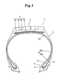
- Fig.1 shows a heavy duty radial tyre for trucks and buses as an embodiment of the present invention.
- each of the bead portion 4 is further provided with a bead reinforcing layer G.
- the bead reinforcing layer G in this example is disposed axially outside the carcass ply turnup portion 6b and is made of rubberised metallic cords 10A (see Figures 12,13) laid crosswise to the adjacent carcass ply cords.
- the carcass 6 in this embodiment is composed of a single ply 6A of metallic cords 10C arranged radially at substantially 90 degrees.
- the belt 7 in this embodiment comprises a radially innermost ply 7A of rubberised parallel cords laid at an angle of from 35 to 65 degrees, and radially outer second, third and fourth plies 7B, 7C and 7D of rubberised parallel cords laid at an angle of from 15 to 35 degrees.
- at least two middle plies 7B and 7C which are crossed plies in this example are made of metallic cords 10.
- all the four plies are made of metallic cords 10B (see Figures 9-11).
- the metallic cord 10C for the carcass 6 is composed of seven to twelve metallic filaments F whose diameter (d) is in a range of from 0.15 to 0.30 mm, wherein the metallic filaments F are grouped into (i) bunches B of two or three or four filaments or (ii) one filament F and bunches B of two or three or four filaments, and they are twisted together at a final twist pitch Pc of from 10 to 25 mm.
- the filaments F of each bunch B are twisted together into the bunch at a twist pitch Pf of from 3 to 20 times the final twist pitch Pc.
- the bunches B each include at least one waved filament FA and at least one unwaved filament FB as shown in Fig.2.
- each bunch and one filament F out of the bunches are generically called an "element".
- Fig.3 is a diagram showing the twisting of the cord.
- Pc final twist
- the degree of the rotation of each element especially bunch is decreased so that the twist pitch Pf becomes 3 to 20 times the twist pitch Pc.
- the direction of the first twist for the bunches B is the same as the direction of the final twist for the cord.
- the filaments, especially waved filaments are each subjected to a rotation around its axis which is in the same direction as the final twist but the degree of rotation is less than the final twist. If the twist pitch Pf is less than 3 times or more than 20 times the final twist pitch Pc, the rubber penetration deteriorates.
- the direction of the rotation of the waved filament around its axis in the finished cord may be reversed as far as it is concerned with the improvement in the rubber penetration.
- the metallic cord 10B for the belt 7 is composed of six to ten metallic filaments F whose diameter (d) is larger than the carcass cord 10C and in a range of from 0.25 to 0.45 mm, wherein similarly to the carcass cord, the metallic filaments F are grouped into (i) bunches B of two or three or four filaments or (ii) one filament F and bunches B of two or three or four filaments, and they are twisted together at a final twist pitch Pc which is in a range of from 10 to 40 mm but usually limited to a range of not more than that of the carcass cord. Further, the bunches B each include at least one waved filament FA and at least one unwaved filament FB. The filaments F of each bunch B are twisted together into the bunch at a twist pitch Pf of from 3 to 20 times the final twist pitch Pc.
- the twisting in the belt cord 10B is made in the same way as the carcass cord 10C.
- the direction of the first twist for the bunches B is the same as the direction of the final twist for the cord.
- the rotation of the waved filaments in the finished cord is in the same direction as the final twist but the degree of rotation is less than the final twist.
- the metallic cord 10A for the bead reinforcing layer G is composed of seven to twelve metallic filaments F whose diameter (d) is in a range of from 0.17 to 0.25 mm.
- the metallic filaments F include at least two waved filaments FA and at least three unwaved filaments FB.
- the three or more unwaved filaments are necessary for decreasing the initial elongation of the cord under light loads.
- the twist structure thereof is rather different from the carcass cord and belt cord as explained later.
- the cross section of the waved filament FA is dotted, and the cross section of the unwaved filament FB is hatched, for convenience sake, in order to distinguish from each other.
- the waved filament FA is two-dimensionally waved at a wave pitch PW and a wave height (h) before being twisted.
- Fig.4 shows an example of the waved filament FA, wherein the waveform is a triangular waveform made up of straight segments 13 of substantially the same length forming an obtuse angle therebetween. Also, a sawtooth waveform made up of alternate long straight segments and short straight segments and the like can be used. Further, A curved waveform devoid of straight segment such as a sinusoidal waveform may be used. But, a waveform including straight segments 13 forming an obtuse angle therebetween is preferably used for the rubber penetration into the finished cord.
- the above-mentioned wave height (h) is defined as the peak-to-peak height of the wave; and the wave pitch Pw is defined as one cycle of the wave.
- the waved filaments FA include at least two kinds of waved filaments FA which are different from each other in respect of the wave pitch Pw.
- the rubber penetration into the cord can be improved although the wave height (h) is relatively low.
- all the waved filaments FA have the same wave pitch Pw and the same wave height (h). If the waved filaments have different wave pitches Pw and different wave heights (h), due to the twist structure mentioned later, tensile stress concentrates on the shortest filament and the filament is liable to break because the filaments are very fine.
- the diameter (d) of the waved filament is less than 0.15 mm, the wave vanishes during twisting the waved filament and the rubber penetration can not be improved.
- the diameter of the waved filament should not be less than 0.15 mm.
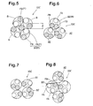
- Fig.5 shows an example of a carcass cord 10C made up of nine metallic filaments F which are grouped into four two-filament bunches B1 and including one waved filament FA and one unwaved filament FB and one remaining unwaved filament FB which are twisted together at the final twist pitch Pc.
- Figs.6, 7 and 8 show other examples made up of nine, ten and twelve metallic filaments F, respectively.
- each bunch B is a two-filament bunch made up of two filaments F or a three-filament bunch made up of three filaments F.
- the wave pitch Pw is set in a range of from 5.0 to 35.0 times, preferably 10.0 to 25.0 times the diameter (d), and the wave height (h) is set in a range of from 0.5 to 4.0 times the diameter (d).
- the wave pitch Pw is less than 5.0 times the diameter (d), the strength of the waved filament liable to decrease. If the wave pitch Pw is more than 35 times the diameter (d), the rubber penetration deteriorates.
- the wave height (h) is less than 0.5 times the diameter (d), the rubber penetration can not be improved. If the wave height (h) is more than 4.0 times the diameter (d), the strength of the waved filament is liable to decrease.
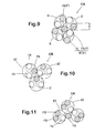
- Fig.9 shows an example of belt cord 10B composed of nine metallic filaments F which are grouped into four two-filament bunches B 1 of one waved filament FA and one unwaved filament FB and the remaining one unwaved filament FB which are twisted at the final twist pitch Pc.
- Figs. 10 and 11 show other examples composed of nine and ten metallic filaments F, respectively.
- each bunch B is a two-filament bunch or three-filament bunch.
- the wave pitch Pw is set in a range of from 5.0 to 35.0 times preferably 10.0 to 25.0 times the diameter (d), and the wave height (h) is set in a range of from 0.2 to 3.0 times preferably 0.5 to 2.0 times the diameter (d).
- cord structures can be applied to not only heavy duty tyres but also light truck tyres.
- the diameter (d) is less than 0.25 mm, it becomes difficult to provide a strength necessitated by the belt. If the diameter (d) is more than 0.45 mm, it is difficult to prevent the belt rigidity from excessively increasing.
- the wave pitch Pw is less than 5.0 times the diameter (d), the strength of the waved filament liable to decrease. If the wave pitch Pw is more than 35 times the diameter (d), the rubber penetration deteriorates.
- the wave height (h) is less than 0.2 times the diameter (d), the rubber penetration can not be improved. If the wave height (h) is more than 3.0 times the diameter (d), the strength of the waved filament is liable to decrease.
- the filament F out of the bunches B (case (ii)) is an unwaved filament FB.
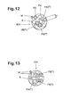
- Figs.12 and 13 show examples of the bead reinforcing cord 10A composed of nine and twelve filaments F, respectively.
- the "two filaments” may be two specific filaments, namely, "two filaments” are the same along the length of the cord. In this case, it can be said that the cord is formed by final-twisting the first-twisted "two filaments" and the remaining filaments.
- the "two filaments" are changed along the longitudinal direction in a predetermined order so as not to concentrate the interchange on specific filaments.
- the cord is composed of filaments (a), (b), (c), (d), (e), (f) and (g), (a and b) are interchanged in a position, (c and d) are interchanged in a subsequent position, (e and f) are interchanged in a further subsequent position, (g and a), (b and c), (d and e) -- continued.
- any two filaments are partially twisted separately from the final twist for the cord.
- each filament is simply gathered as a single bunch, and the bunch is rotated around its axis. This rotation corresponding to the above-mentioned final-twist.
- each filament is subjected to a rotation around its axis which is in the same direction and the same degree as the rotation of the bunch.
- the unity of the filaments F is less in comparison with the carcass cord 10C and belt cord 10B. Therefore, a wrapping wire is wound around the filaments F.
- the winding direction is reverse to the final-twist direction.
- the winding pitch is set in a range of from 3.0 to 7.0 mm.
- the diameter of the wrapping wire is set in a range of from 0.13 to 0.17 mm.
- the waved filament FA is, before being twisted, two-dimensionally waved at a wave pitch Pw and a wave height (h) so as to be made up of straight segments 13. And all the waved filaments FA have the same wave height (h) and wave pitch Pw.
- the wave pitch Pw is set in a range of from 10.0 to 35.0 times the diameter (d).
- the wave height (h) is set in a range of from 0.5 to 4.0 times the diameter (d).
- twist pitch is less than 10 mm, as the initial elongation of the cord increases and it becomes difficult to use in the bead reinforcing layer. If the twist pitch is more than 30 mm, the cord becomes difficult to handle, and the form stability of the reinforcing layer decreases.
- the wave pitch Pw is less than 10.0 times the diameter (d)
- the strength of the waved filament liable to decrease. If the wave pitch Pw is more than 35 times the diameter (d), the rubber penetration deteriorates.
- the wave height (h) is less than 0.5 times the diameter (d), the rubber penetration can not be improved. If the wave height (h) is more than 4.0 times the diameter (d), the strength of the waved filament is liable to decrease.
- hard drawn steel wires whose carbon content is 0.65 to 0.88 wt% are preferably used. If the carbon content is less than 0.65 wt%, the strength of the filament tends to be insufficient. If the carbon content is more than 0.88 wt%, the filament decreases in the bending strength.
- the metallic filaments F and wrapping wire W are preferably provided on the surface with a coating for improving the adhesion to the surrounding elastomer.
- a coating for improving the adhesion to the surrounding elastomer.
- various resins, metal which acts during vulcanisation and the like can be used.
- Test tyres of size 11R22.5 for trucks and buses, having the same structure except for the carcass cords were made and tested as follows.
- the carcass was composed of a single ply of cords arranged radially at 90 degrees with respect to the tyre equator and a cord count of 40/5cm.
- the belt was composed of four plies of parallel steel cords having a 3+8+13X0.23 conventional structure laid at +65, +20, -20, -20 degrees and a cord count of 20/5cm.
- Test tyres of two sizes, 11R22.5 for trucks and buses and 205/60R17.5 for light trucks having the same structure except for the belt cords were made and tested as follows.
- the carcass was composed of a single ply of steel cords having a 3+9X0.23 conventional structure arranged at 90 degrees and a cord count of 35/5cm.
- the belt was composed of four plies of cords laid at +65, +20, -20 and -20 and a cord count of 20/5 cm.
- the carcass was composed of two plies of polyester fibre cords having a 1670dtex/2 structure arranged at 88 degrees and a cord count of 50/5cm.
- the belt was composed of two plies of cords laid at +18 and -18 degrees and a cord count of 35/5 cm.
- Test tyres of size 11R22.5 for trucks and buses having the same structure except for the bead reinforcing cords were made and tested as follows.
- the cord was taken out of the tyre together with the surrounding topping rubber, and the topping rubber was carefully removed from the surface of the cord. Then, two adjacent filaments were taken out therefrom along 10 cm long using a knife, and the length of the part surrounded by the two removed filaments and the remaining filaments into which the rubber had completely penetrated was measured to obtain the percentage of this length to the total length of 10 cm as the rubber penetration %. Such a determination was made on ten positions per tyre and the average thereof was adopted.
- the tyre was disassembled after running about 200,000 km, and the steel cords were checked for corrosion. The results are indicated by an index based on Ref.1 being 100. The smaller the index, the smaller the corrosion.
- the bending rigidity of the test cord was measured with a V-5 stiffness tester model 150-D of Taber Industries, U.S.A., as the force in gram centimetre required to bend the cord 15 degrees.
- a cord length of 1,000 mm was coiled into a loop of 200 mm diameter.
- the shape retention rate E of each cord was divided by that of Ex. and converted into the reciprocal number and further multiplied by 100. The larger the value, the better the shape retention.
- the cord strength is shown as a diminution in % of the strength of the test cord from that of a standard cord, wherein the standard cord for each test cord is a compact cord that is the same as the test cord in respect of the material, the number of the filaments, the filament diameter, and the final twist pitch, except that all the filaments are unwaved and the first twist pitch is the same as the final twist pitch.
- the smaller the value the higher the strength.
- Fig. 14 which shows the strength diminution and rubber penetration as a function of the value of d ⁇ h PW .
- the present invention can be suitably applied to not only heavy duty tyres but also light truck tyres, passenger car tyres and the like.
- TABLE 1 Tyre Ref.1 Ref.2 Ref.3 Ref.4 Ex.1 Ex.2 Ex.3 Ex.4 Cord structure 1X9X0.20 1X9X0.20 1X9X0.20 1X9X0.20 1X9X0.20 1X9X0.20 1X9X0.20 1X12X0.15 Carbon content (%) 082 0.82 0.82 0.82 0.82 0.82 0.82 0.82 Twist pitch Pc (mm) 17 17 17 17 17 17 17 17 17 15 Bunch 1 Twist pitch Pf 0 0 0 10XPc 10XPc 10XPc 7XPc No.
Description
- The present invention relates to a pneumatic tyre reinforced by metallic cords, more particularly to an improved metallic cord in which rubber penetration is improved without being increased in the cord diameter.
- In pneumatic tyres, especially radial tyres for trucks, buses, light trucks and the like, steel cords are widely used as reinforcing cords for the carcass, belt, bead reinforcing layers and the like.
- In recent years, in order to improve rubber penetration into such a steel cord, an invention was made, which is to use a waved filament in making the steel cord.
- Generally, in the process of making a steel cord, as well known in the tyre cord art, in order to prevent twisted filaments from loosening, the steel filaments are twisted together in one direction while giving each filament a rotation around its axis which rotation is reverse to this twist direction and the degree of the rotation is the same as the twist. In the finished cord, accordingly, each filament is not subjected to rotation around its axis.
- In such a conventional twisting method, if a waved filament is used, it is necessary to wave steel filaments greatly in order to improve rubber penetration.
- When steel filaments are waved greatly, it is inevitable that the diameter of the finished cord increases and the initial elongation of the finished cord under light loads increases. As a result, the thickness and weight of the cord-reinforced layers in a tyre are increased and further the reinforcing effect tends to decrease.
- EP-A-0 551 124 discloses a pneumatic tyre with a belt comprising a waveform or helical core steel filament and a plurality of sheath steel filaments disposed around the core steel filament.
- EP-A-0 976 583 discloses a pneumatic tyre having the features of the preamble of
claim 1. - It is an object of the present invention to provide a pneumatic tyre with a cord-reinforced layer as a belt, the metallic cords of which are improved in rubber penetration without increasing the cord diameter.
- This object is achieved with a pneumatic tyre having the features of
claim 1. Subclaims are directed to preferable embodiments. - Therefore, until the cord is rubberised, the two-dimensionally waved filaments become unstable, and gaps which effectively work on rubber penetration can be formed between the filaments without increasing the thickness of the finished cord.
- Embodiments of the present invention will now be described in detail in conjunction with the accompanying drawings, in which:
- Fig.1 is a cross sectional view of a tyre according to the present invention;
- Fig.2 is a schematic perspective view of a twisted bunch of a waved filament and unwaved filament;
- Fig.3 is a diagram showing the twisting of a metallic cord;
- Fig.4 is a schematic view of an example of the waved filament for explaining the wave pitch and height;
- Fig.5 is a schematic cross sectional view of an example of the carcass cord showing an example of the filament arrangement;
- Figs.6, 7 and 8 each show another example of the filament arrangement of the carcass cord;
- Fig.9 is a schematic cross sectional view of an example of the belt cord showing an example of the filament arrangement;
- Figs.10 and 11 each show another example of the filament arrangement of the belt cord;
- Figs.12 and 13 each show a schematic cross sectional view of an example of the belt cord showing an example of the filament arrangement; and
- Fig. 14 is a graph showing the cord strength and rubber penetration as a function of a

- In the drawings, a pneumatic
radial tyre 1 according to the present invention comprises atread portion 2, a pair ofsidewall portions 3 and a pair ofbead portions 4 so as to form a toroidal shape. The tyre is provided with acarcass 6 extending between thebead portions 4, and abelt 7 disposed radially outside thecarcass 6 in thetread portion 2. - The
carcass 6 comprises at least one ply of cords arranged radially at an angle of from 70 to 90 degrees with respect to the tyre equator and extending between thebead portions 4 through thetread portion 2 andsidewall portions 3 and turned up around abead core 5 in eachbead portion 4 from the inside to the outside of the tyre so as to form a pair ofturnup portions 6b and amain portion 6a therebetween. - Between the
main portion 6a andturnup portion 6b in each of the bead portions, there is disposed arubber bead apex 8 extending radially outwardly from thebead core 5 and tapering towards its radially outer end. - The
belt 7 comprises at least two crossed plies of parallel cords laid at an angle of from about 5 to about 65 degrees with respect to the tyre equator. In the case of heavy duty tyres, thebelt 7 is usually composed of three or four plies. In the case of light truck tyres, thebelt 7 is usually composed of two or three plies. In the case of passenger tyres, thebelt 7 is usually composed of two plies. - Fig.1 shows a heavy duty radial tyre for trucks and buses as an embodiment of the present invention.
- In this embodiment, each of the
bead portion 4 is further provided with a bead reinforcing layer G. The bead reinforcing layer G in this example is disposed axially outside the carcassply turnup portion 6b and is made of rubberisedmetallic cords 10A (see Figures 12,13) laid crosswise to the adjacent carcass ply cords. - The
carcass 6 in this embodiment is composed of asingle ply 6A ofmetallic cords 10C arranged radially at substantially 90 degrees. - The
belt 7 in this embodiment comprises a radiallyinnermost ply 7A of rubberised parallel cords laid at an angle of from 35 to 65 degrees, and radially outer second, third andfourth plies plies 7A to 7D, at least twomiddle plies metallic cords 10. In this example, all the four plies are made ofmetallic cords 10B (see Figures 9-11). - The
metallic cord 10C for thecarcass 6 is composed of seven to twelve metallic filaments F whose diameter (d) is in a range of from 0.15 to 0.30 mm, wherein the metallic filaments F are grouped into (i) bunches B of two or three or four filaments or (ii) one filament F and bunches B of two or three or four filaments, and they are twisted together at a final twist pitch Pc of from 10 to 25 mm. The filaments F of each bunch B are twisted together into the bunch at a twist pitch Pf of from 3 to 20 times the final twist pitch Pc. Further, the bunches B each include at least one waved filament FA and at least one unwaved filament FB as shown in Fig.2. - Hereinafter, each bunch and one filament F out of the bunches (in case (ii)) are generically called an "element".
- Fig.3 is a diagram showing the twisting of the cord. A single bunch of "elements" is rotated around its axis. This corresponding to the final twist (pitch=Pc). By this rotation, each element is essentially subjected to a rotation around the axis of the element which is in the same direction and the same degree (Pc=Pf) as the above-mentioned rotation. In the
metallic cord 10C, however, the degree of the rotation of each element especially bunch is decreased so that the twist pitch Pf becomes 3 to 20 times the twist pitch Pc. Thus, the direction of the first twist for the bunches B is the same as the direction of the final twist for the cord. As a result, in the finished cord, the filaments, especially waved filaments are each subjected to a rotation around its axis which is in the same direction as the final twist but the degree of rotation is less than the final twist. If the twist pitch Pf is less than 3 times or more than 20 times the final twist pitch Pc, the rubber penetration deteriorates. - Incidentally, the direction of the rotation of the waved filament around its axis in the finished cord may be reversed as far as it is concerned with the improvement in the rubber penetration.
- The
metallic cord 10B for thebelt 7 is composed of six to ten metallic filaments F whose diameter (d) is larger than thecarcass cord 10C and in a range of from 0.25 to 0.45 mm, wherein similarly to the carcass cord, the metallic filaments F are grouped into (i) bunches B of two or three or four filaments or (ii) one filament F and bunches B of two or three or four filaments, and they are twisted together at a final twist pitch Pc which is in a range of from 10 to 40 mm but usually limited to a range of not more than that of the carcass cord. Further, the bunches B each include at least one waved filament FA and at least one unwaved filament FB. The filaments F of each bunch B are twisted together into the bunch at a twist pitch Pf of from 3 to 20 times the final twist pitch Pc. - The twisting in the
belt cord 10B is made in the same way as thecarcass cord 10C. Thus, the direction of the first twist for the bunches B is the same as the direction of the final twist for the cord. The rotation of the waved filaments in the finished cord is in the same direction as the final twist but the degree of rotation is less than the final twist. - The
metallic cord 10A for the bead reinforcing layer G is composed of seven to twelve metallic filaments F whose diameter (d) is in a range of from 0.17 to 0.25 mm. - The metallic filaments F include at least two waved filaments FA and at least three unwaved filaments FB. The three or more unwaved filaments are necessary for decreasing the initial elongation of the cord under light loads.
- The twist structure thereof is rather different from the carcass cord and belt cord as explained later.
- In the drawings, the cross section of the waved filament FA is dotted, and the cross section of the unwaved filament FB is hatched, for convenience sake, in order to distinguish from each other.
- The waved filament FA is two-dimensionally waved at a wave pitch PW and a wave height (h) before being twisted.
- Fig.4 shows an example of the waved filament FA, wherein the waveform is a triangular waveform made up of
straight segments 13 of substantially the same length forming an obtuse angle therebetween. Also, a sawtooth waveform made up of alternate long straight segments and short straight segments and the like can be used. Further, A curved waveform devoid of straight segment such as a sinusoidal waveform may be used. But, a waveform includingstraight segments 13 forming an obtuse angle therebetween is preferably used for the rubber penetration into the finished cord. - As shown in Fig.4, the above-mentioned wave height (h) is defined as the peak-to-peak height of the wave; and the wave pitch Pw is defined as one cycle of the wave.
- At least in the case of
belt card 10B and preferably also in the case ofcarcass cord 10C, when the bunch B includes two or more waved filaments FA, the waved filaments FA include at least two kinds of waved filaments FA which are different from each other in respect of the wave pitch Pw. Thereby, the rubber penetration into the cord can be improved although the wave height (h) is relatively low. It may be possible to change the wave heights (h) between the different kinds of waved filaments FA. But, it is preferable not to largely change the wave heights (h), namely, the different kinds of waved filaments FA have substantially the same wave heights (h) in order to avoid an excessive decrease of the cord strength. - In the case of bead reinforcing cord, however, it is preferable that all the waved filaments FA have the same wave pitch Pw and the same wave height (h). If the waved filaments have different wave pitches Pw and different wave heights (h), due to the twist structure mentioned later, tensile stress concentrates on the shortest filament and the filament is liable to break because the filaments are very fine.
- If the diameter (d) of the waved filament is less than 0.15 mm, the wave vanishes during twisting the waved filament and the rubber penetration can not be improved. Thus, the diameter of the waved filament should not be less than 0.15 mm.
- Fig.5 shows an example of a
carcass cord 10C made up of nine metallic filaments F which are grouped into four two-filament bunches B1 and including one waved filament FA and one unwaved filament FB and one remaining unwaved filament FB which are twisted together at the final twist pitch Pc. - Figs.6, 7 and 8 show other examples made up of nine, ten and twelve metallic filaments F, respectively.
- In Fig.6, three three-filament bunches B2 including one waved filament FA and two unwaved filaments FB are final twisted.
- In Fig.7, two two-filament bunches B1 and two three-filament bunches B2 are final twisted.
- In Fig.8, two three-filament bunches B2 including one waved filament FA and two unwaved filaments FB and two three-filaments bunches B3 including two waved filaments FA and one unwaved filament FB are final twisted.
- As shown in Figs.6-8, it is preferable that each bunch B is a two-filament bunch made up of two filaments F or a three-filament bunch made up of three filaments F.
- It is important to the waved filament FA that the wave pitch Pw is set in a range of from 5.0 to 35.0 times, preferably 10.0 to 25.0 times the diameter (d), and the wave height (h) is set in a range of from 0.5 to 4.0 times the diameter (d).
- Further, it is preferable to limit the value

- In heavy duty tyres for trucks, buses and the like, as the carcass cords, steel cords having a 3+9 structure or 3+9+15 structure have been widely used. The above-mentioned
metallic cords 10C were designed as a substitute for such conventional cords. If the diameter (d) is less than 0.15 mm, it becomes difficult to provide the strength required by the carcass of a heavy duty tyre. If the diameter (d) is more than 0.30 mm, it becomes difficult to provide the flexibility necessitated for the carcass of a heavy duty tyre. - If the wave pitch Pw is less than 5.0 times the diameter (d), the strength of the waved filament liable to decrease. If the wave pitch Pw is more than 35 times the diameter (d), the rubber penetration deteriorates.
- If the wave height (h) is less than 0.5 times the diameter (d), the rubber penetration can not be improved. If the wave height (h) is more than 4.0 times the diameter (d), the strength of the waved filament is liable to decrease.
- Fig.9 shows an example of
belt cord 10B composed of nine metallic filaments F which are grouped into four two-filament bunches B 1 of one waved filament FA and one unwaved filament FB and the remaining one unwaved filament FB which are twisted at the final twist pitch Pc. - Figs. 10 and 11 show other examples composed of nine and ten metallic filaments F, respectively.
- In the inventive example of Fig. 10, three three-filament bunches B2 of two waved filament FA and one unwaved filament FB are twisted.
- In Fig. 11, three three-filament bunches B3 of one waved filament FA and two unwaved filament FB and the remaining one unwaved filament FB are twisted.
- As shown in Figs.9-11, it is preferable that each bunch B is a two-filament bunch or three-filament bunch.
- It is important to the waved filament FA that the wave pitch Pw is set in a range of from 5.0 to 35.0 times preferably 10.0 to 25.0 times the diameter (d), and the wave height (h) is set in a range of from 0.2 to 3.0 times preferably 0.5 to 2.0 times the diameter (d).
- It is preferable to set the value

- These cord structures can be applied to not only heavy duty tyres but also light truck tyres.
- Hitherto, in heavy duty tyres for trucks, buses and the like, steel cords having a 3+6 structure (two filament diameters) or 2+7 structure (one filament diameter) have been widely used as belt cords. As a substitute for such conventional cords for heavy duty tyres, it is preferable to set the diameter (d) in a range of from 0.30 to 0.45 mm.
- On the other hand, in light truck tyres, steel cords having a 2+6 or 3+6 or 2+7 structures have been widely used as the belt cords. As a substitute for such conventional cords for light truck tyres, it is preferable to set the diameter (d) in a range of from 0.25 to 0.35 mm.
- If the diameter (d) is less than 0.25 mm, it becomes difficult to provide a strength necessitated by the belt. If the diameter (d) is more than 0.45 mm, it is difficult to prevent the belt rigidity from excessively increasing.
- If the wave pitch Pw is less than 5.0 times the diameter (d), the strength of the waved filament liable to decrease. If the wave pitch Pw is more than 35 times the diameter (d), the rubber penetration deteriorates.
- If the wave height (h) is less than 0.2 times the diameter (d), the rubber penetration can not be improved. If the wave height (h) is more than 3.0 times the diameter (d), the strength of the waved filament is liable to decrease.
- In the case of the
belt cord 10B and the above-mentionedcarcass cord 10C, it is preferable that the filament F out of the bunches B (case (ii)) is an unwaved filament FB. - Figs.12 and 13 show examples of the
bead reinforcing cord 10A composed of nine and twelve filaments F, respectively. - In Fig. 12, five waved filaments FA and four unwaved filaments FB as a bunch are twisted into the cord while interchanging the positions of two filaments.
- In Fig.13, six waved filaments FA and six unwaved filaments FB as a bunch are twisted into the cord while interchanging the positions of two filaments.
- Here, the meaning of "interchanging the positions of two filaments" is as follows.
- When a plurality of filaments, as a single bunch, are twisted, the relative positions of the filaments are substantially not changed along the longitudinal direction, and closed spaces are liable to be formed among the filaments.
- Such closed spaces can be broken by upsetting the positional balance of the filaments. In order to effectively upset the positional balance, the positions of two filaments are intentionally interchanged.
- The "two filaments" may be two specific filaments, namely, "two filaments" are the same along the length of the cord. In this case, it can be said that the cord is formed by final-twisting the first-twisted "two filaments" and the remaining filaments.
- It is however, preferable that the "two filaments" are changed along the longitudinal direction in a predetermined order so as not to concentrate the interchange on specific filaments. For example, provided that the cord is composed of filaments (a), (b), (c), (d), (e), (f) and (g), (a and b) are interchanged in a position, (c and d) are interchanged in a subsequent position, (e and f) are interchanged in a further subsequent position, (g and a), (b and c), (d and e) -- continued. In this case, it may be said that any two filaments are partially twisted separately from the final twist for the cord.
- Further, the meaning that "the filaments as a bunch are twisted into the cord" is as follows.
- All the filaments are simply gathered as a single bunch, and the bunch is rotated around its axis. This rotation corresponding to the above-mentioned final-twist. Thus, in the finished cord, each filament is subjected to a rotation around its axis which is in the same direction and the same degree as the rotation of the bunch.
- In such a twisted structure, the unity of the filaments F is less in comparison with the
carcass cord 10C andbelt cord 10B. Therefore, a wrapping wire is wound around the filaments F. The winding direction is reverse to the final-twist direction. The winding pitch is set in a range of from 3.0 to 7.0 mm. The diameter of the wrapping wire is set in a range of from 0.13 to 0.17 mm. - In the bead reinforcing cord, the waved filament FA is, before being twisted, two-dimensionally waved at a wave pitch Pw and a wave height (h) so as to be made up of
straight segments 13. And all the waved filaments FA have the same wave height (h) and wave pitch Pw. The wave pitch Pw is set in a range of from 10.0 to 35.0 times the diameter (d). The wave height (h) is set in a range of from 0.5 to 4.0 times the diameter (d). The value
- Hitherto, in heavy duty tyres for trucks, buses and the like, steel cords having a 3+9 or 3+9+15 structure have been widely used in the bead reinforcing layer. The above-mentioned
metallic cord 10A was designed as a substitute for such conventional cords. If the diameter (d) is less than 0.17 mm, it is difficult to provide a rigidity necessitated by the bead reinforcing layer, and tyre durability decreases. If the diameter (d) is more than 0.25 mm, the bead reinforcing layer loses flexibility and there is a possibility of separation failure if the bead portion undergoes excessively large deformation repeatedly. - If the twist pitch is less than 10 mm, as the initial elongation of the cord increases and it becomes difficult to use in the bead reinforcing layer. If the twist pitch is more than 30 mm, the cord becomes difficult to handle, and the form stability of the reinforcing layer decreases.
- If the wave pitch Pw is less than 10.0 times the diameter (d), the strength of the waved filament liable to decrease. If the wave pitch Pw is more than 35 times the diameter (d), the rubber penetration deteriorates.
- If the wave height (h) is less than 0.5 times the diameter (d), the rubber penetration can not be improved. If the wave height (h) is more than 4.0 times the diameter (d), the strength of the waved filament is liable to decrease.
- As to the material of the filaments F and wrapping wire W of the above-mentioned
cords - Further, the metallic filaments F and wrapping wire W are preferably provided on the surface with a coating for improving the adhesion to the surrounding elastomer. For the coating, various resins, metal which acts during vulcanisation and the like can be used.
- In the above-mentioned examples of the carcass cord, belt cord and bead reinforcing cord, all the metallic filaments F in each cord have the same diameter (d).
- Various experimental steel cords were made, and test tyres were made using the cords. Then, the following comparison tests were conducted. The test results are shown in Tables 1, 2 and 3.
- Test tyres of size 11R22.5 for trucks and buses, having the same structure except for the carcass cords were made and tested as follows. The carcass was composed of a single ply of cords arranged radially at 90 degrees with respect to the tyre equator and a cord count of 40/5cm. The belt was composed of four plies of parallel steel cords having a 3+8+13X0.23 conventional structure laid at +65, +20, -20, -20 degrees and a cord count of 20/5cm.
- The test results are shown in Table 1.
- Test tyres of two sizes, 11R22.5 for trucks and buses and 205/60R17.5 for light trucks having the same structure except for the belt cords were made and tested as follows.
- In the case of the 11R22.5 heavy duty tyre, the carcass was composed of a single ply of steel cords having a 3+9X0.23 conventional structure arranged at 90 degrees and a cord count of 35/5cm. The belt was composed of four plies of cords laid at +65, +20, -20 and -20 and a cord count of 20/5 cm.
- In the case of the 205/60R17.5 light truck tyre, the carcass was composed of two plies of polyester fibre cords having a 1670dtex/2 structure arranged at 88 degrees and a cord count of 50/5cm. The belt was composed of two plies of cords laid at +18 and -18 degrees and a cord count of 35/5 cm.
- The test results are shown in Table 2.
- Test tyres of size 11R22.5 for trucks and buses having the same structure except for the bead reinforcing cords were made and tested as follows.
- The test results are shown in Table 3. In Table 3, item "Filament rotation", "S" means that each filament is subjected to a rotation in the same direction as the twist direction by the twisting. "N" means that each filament is not subjected to a rotation by the twisting because the filament is rotated in the counter direction during twisting.
- Test methods and procedures are as follows.
- The cord was taken out of the tyre together with the surrounding topping rubber, and the topping rubber was carefully removed from the surface of the cord. Then, two adjacent filaments were taken out therefrom along 10 cm long using a knife, and the length of the part surrounded by the two removed filaments and the remaining filaments into which the rubber had completely penetrated was measured to obtain the percentage of this length to the total length of 10 cm as the rubber penetration %. Such a determination was made on ten positions per tyre and the average thereof was adopted.
- The tyre was disassembled after running about 200,000 km, and the steel cords were checked for corrosion. The results are indicated by an index based on Ref.1 being 100. The smaller the index, the smaller the corrosion.
- Further, the steel cords were taken out and the cord strength was measured. The results are indicated as percentage to the original strength.
- The bending rigidity of the test cord was measured with a V-5 stiffness tester model 150-D of Taber Industries, U.S.A., as the force in gram centimetre required to bend the
cord 15 degrees. - A cord length of 1,000 mm was coiled into a loop of 200 mm diameter. The loop was collapsed gradually in fifteen seconds as follows: the loop was put on a horizontal plane; and one of two oppositely opposed points was fixed, and the other point is pressed towards the fixed point so that the two points contact each other. The collapsed state was maintained for ten seconds. Then, the pressing force was decreased gradually in fifteen seconds to allow the loop to return to its original shape. And the distance L between the two points was measured to obtain the shape retention rate E =(L/200)X100. The shape retention rate E of each cord was divided by that of Ex. and converted into the reciprocal number and further multiplied by 100. The larger the value, the better the shape retention.
- From the tyre, a specimen of the bead reinforcing layer was cut out, and the force required to pull a
cord 15 mm out of the specimen was measured. - Here, the cord strength is shown as a diminution in % of the strength of the test cord from that of a standard cord, wherein the standard cord for each test cord is a compact cord that is the same as the test cord in respect of the material, the number of the filaments, the filament diameter, and the final twist pitch, except that all the filaments are unwaved and the first twist pitch is the same as the final twist pitch. Thus, the smaller the value, the higher the strength.
- From the test results, it was confirmed that although the cord diameter is decreased, rubber penetration, strength, initial elongation and the like can be improved.
- Further, as shown in Fig. 14 which shows the strength diminution and rubber penetration as a function of the value of


- The present invention can be suitably applied to not only heavy duty tyres but also light truck tyres, passenger car tyres and the like.
TABLE 1 Tyre Ref.1 Ref.2 Ref.3 Ref.4 Ex.1 Ex.2 Ex.3 Ex.4 Cord structure 1X9X0.20 1X9X0.20 1X9X0.20 1X9X0.20 1X9X0.20 1X9X0.20 1X9X0.20 1X12X0.15 Carbon content (%) 082 0.82 0.82 0.82 0.82 0.82 0.82 0.82 Twist pitch Pc (mm) 17 17 17 17 17 17 17 15 Bunch 1 Twist pitch Pf 0 0 0 0 10XPc 10XPc 10XPc 7XPc No. of filaments Waved 0 3(A:A:A) 3(A:A:A) 2(A:A) 2(A.B) 1(A) 2(A:A) 2(A:B) Unwaved 9 0 0 1 1 2 1 2 Bunch 2 Twist pitch Pf 0 0 0 0 10XPc 10XPc 10XPc 7XPc No. of filaments Waved 3(A:A:A) 3(A:A:A) 2(A:A) 2(A:B) 1(A) 2(A:A) 2(A:B) Unwaved 0 0 1 1 2 1 2 Bunch 3 Twist pitch Pf 0 0 0 0 10XPc 10XPc 10XPc 7XPc No. of filaments Waved 3(A:A:A) 3(A:A:A) 2(A:A) 2(A:B) 1(A) 2(A:A) 2(A:B) Unwaved 0 0 1 1 2 1 2 Wave A A A A:B A A A:B Pitch Pw(mm) 10 5 10 5.0:3.0 5 4 2.0:4.0 Height h (mm) 0.5 1 1 0.45 0.5 0.5 0.4 Cord characteristics Cord diameter (mm) 071 085 083 0.82 0.75 0.73 0.75 0.78 Strength (N/sq.mm) 3052 2980 2990 3000 3020 3030 3025 3010 Strength diminution (%) 0.2 2.2 2.3 2 1 1.2 1.2 2 Elongation (%) @ 50N 0 107 0.125 0.128 0.108 0.108 0.107 0.108 0.109 Bending rigidity (gf. cm) 23 20 20 21 21 22 21 20 Rubber penetration (%) 0 78 77 82 98 95 96 95 Corrosion (index) 100 55 53 45 11 20 18 25 Reserved strength (index) 88 92 93 95 92 95 93 91 TABLE 2 Tyre Ref.1 Ref.2 Ref.3 Ref.4 Ref.5 Ex.1 Ex.2 Ex.3 Ex.4 Ex.5 Tyre size 11 R22.5 11 R22.5 11 R22.5 11 R22.5 205160R17.5 11 R22.5 11 R22.5 11 R22.5 205160R17.5 205160R17.5 Cord structure 1 X9X0.38 1 X9X0.38 1X9X0.38 1 X9X0.38 1 X9X0.30 1 X9X0.38 1 X9X0.38 1 X9X0 38 1 X9X0.30 1 X7X0.25 Carbon content (%) 0.82 0.82 0.82 0.82 0.82 0.82 0.82 0.82 0.82 0.82 Twist pitch Pc(mm) 18 18 18 7 18 18 18 18 18 18 Bunch 1 Twist pitch Pf 0 0 0 0 0 10XPc 10XPc 10XPc 10XPc 10XPc No. of filaments Waved 0 3(A;A;A) 3(A,B,C) 2(A;B) 3(A;A;A) 2(A;B) 2(A;A) 1(A) 2(A;B) 2(A;A) Unwaved 9 0 0 1 0 1 1 2 1 1 Bunch 2 Twist pitch Pf 0 0 0 0 0 10XPc 10XPc 10XPc 10XPc 10XPc No. of filaments Waved 3(A;A;A) 3(A;B;C) 2(A;B) 3(A;A;A) 2(A;B) 2(A;A) 1(A) 2(A;B) 2(A;A) Unwaved 0 0 1 0 1 1 2 1 1 Bunch 3 Twist pitch Pf 0 0 0 0 0 10XPc 10XPc 10XPc 10XPc 10XPc No. of filaments Waved 3(A;A;A) 3(A,B;C) 2(A;B) 3(A;A;A) 2(A;B) 2(A;A) 1(A) 2(A;B) 0 Unwaved 0 0 1 0 1 1 2 1 1 Wave A A;B;C A;B A A;B A A A;B A Pitch Pw(mm) 5 3.0;5.0;6.3 1.0;15 5 5.0,6.3 5 5 5.0;6.3 5 Height h (mm) 0.25 0.25,0.25;0.34 0.25 0.25 0.25;0.34 0.25 0.25 0.25 0.25 Cord characteristics Cord diameter (mm) 14 1.5 156 1.48 1.52 1.48 1.5 1.45 1.15 0.78 Strength (N/sq.mm) 3013 2980 2978 3000 2980 3021 3025 3030 3035 3009 Strength diminution (%) 0 2.9 3 2.5 2.9 2.5 2.5 2.2 2.6 2.7 Elongation (%) @ 50N 0.052 0.069 0.065 0.012 0089 0.012 0.012 0.002 0.015 0.013 bending rigidity (gf. cm) 260 220 215 232 91 232 231 235 96 28 Rubber penetration (%) 0 91 93 92 91 97 95 95 96 93 Corrosion (index) 100 86 89 90 86 8 10 15 9 13 Reserved strength (index) 86 96 96 95 95 95 95 95 93 93 TABLE 3 Tyre Ref.1 Ref.2 Ref.3 Ref 4 Ref 5 Ref.6 Ex.1 Ex.2 Ex.3 Ex.4 Cord structure 1X7X0.23+ 1X7X023+ 1X7X0.23+ 1X9X0.20+ 1X9X0.20+ 1X9X0.20+ 1X7X0.23+ 1X7X0 23+ 1X9X0.20+ 1X9X0.20+ 1X0.15 1X0.15 1X0.15 1X015 1X0.15 1X0.15 1X0.15 1X0.15 1X0.15 1X0.15 Carbon content (%) 0.82 0.82 0.82 0.82 0.82 0.82 0.82 0.82 0.82 0.82 Twist pitch (mm) 15 15 15 18 18 18 15 15 18 18 Filament rotation N N S N N S S S S S No. of filaments Waved 0 3 7 0 3 9 3 4 3 5 Unwaved 7 4 0 9 6 0 4 3 6 4 Wave 2-D 2-D 2-D 2-D 2-D 2-D 2-D 2-D Height h (mm) 0.1 0.3 1.5 0.45 0.3 0.45 0.45 0.5 Pitch Pw (mm) 2 3.3 10 5 33 4.5 5 0.45 dXh/Pw 0.012 0021 0.03 0.018 0.021 0.023 0.018 0.022 Wrapping wire Dia. (mm) 0.15 0.15 0.15 0.15 0.15 0.15 0.15 0.15 0.15 0.15 Winding pitch (mm) 5 5 5 5 5 5 5 5 5 5 Cord characteristics Cord diameter (mm) 0.7 082 08 11 1.23 1.19 0.78 0.8 1.21 1.28 Strength (N/sq.mm) 3010 2980 2930 3035 3010 2980 2950 2920 3010 2980 Strength diminution (%) 0 1.9 3.1 0 2.5 3.2 2.1 2.8 2 2.7 Elongation (%) @ 50N 0.118 0 12 0.148 0.119 0.121 0152 0.12 0.122 0.121 0.123 Bending rigidity (gf cm) 29 27 24 33 31 29 28 27 31 30 Rubber penetration (%) 0 91 95 0 92 94 97 98 96 95 Corrosion (index) 100 20 18 100 23 20 11 15 12 14 Reserved strength (%) 89 95 97 85 94 95 96 97 95 97 Shape retention (index) 95 99 101 95 100 101 100 101 102 103 Pull-out resistance (N/15mm) 135 181 192 128 173 177 191 195 181 185 (broken) (broken) (broken) (broken) (broken) (broken) (broken) (broken)
Claims (7)
- A pneumatic tyre comprising- a belt (7) formed by a cord-reinforced layer made of metallic belt cords (10B) and being disposed radially outside a carcass (6) in a tread portion (2)- each said metallic belt cord (10B) made up of six to ten metallic filaments (F) whose diameter (d) is in a range of from 0.25 to 0.45 mm,- said six to ten metallic filaments being grouped into a plurality of elements (B1,B2,B3), said plurality of elements being (i) bunches of two or three or four filaments (F), or (ii) one filament (F) and bunches of two or three or four filaments (F),- each said bunch (B) including at least one waved filament (FA) and at least one unwaved filament (FB),- the waved filament (FA) being two-dimensionally waved at a wave pitch (PW) and wave height (h) before twisted,- the wave pitch (PW) being in a range of from 5.0 to 30.0 times the diameter (d) of the filament,- the wave height (h) being in a range of from 0.2 to 3.0 times the diameter (d) of the filament, and- said plurality of elements being twisted together into the cord at a twist pitch (Pc) of from 10 to 40 mm so that the two-dimensionally waved filaments (FA) are each subjected to a certain rotation around its axischaracterised in that at least one bunch (B) includes plural kinds of waved filaments (FA) having different wave pitches (PW).
- A pneumatic tyre according to claim 1, characterised in that the filaments (F) in each said bunch (B) are twisted at a twist pitch (Pf) of from 3 to 20 times the twist pitch (Pc).
- A pneumatic tyre according to claim 1 or 2, characterised in that each said bunch (B) is made up of two or three filaments (F).
- A pneumatic tyre according to any of claims 1 to 3, characterised in that the diameter (d) is in a range of from 0.25 to 0.35 mm.
- A pneumatic tyre according to any of claims 1 to 3, characterised in that the diameter (d) is in a range of from 0.30 to 0.45 mm.
- A pneumatic tyre according to claim 1, characterised in that said carcass (6) extends between bead portions (4) through a tread portion (2) and sidewall portions (3) and comprises at least one ply of carcass cords (10c) extending between the bead portions (4), each said carcass cord (10c) being made up of seven to twelve metallic filaments (F) whose diameter (d) is in a range of from 0.15 to 0.30 mm, said seven to twelve metallic filaments (F) being grouped into a plurality of elements (B1), said plurality of elements being (i) bunches (B) of two or three or four filaments, or (ii) one filament (F) and bunches (B) of two or three or four filaments, said plurality of elements (F, B) being twisted at a twist pitch(Pc) of from 10 to 25 mm, each bunch including at least one waved filament (FA) and at least one unwaved filament (FB), the waved filament (FA) being two-dimensionally waved at a wave pitch (PW) and wave height (h) before being twisted, wherein the wave pitch (PW) is in a range of from 5.0 to 30.0 times the diameter (d) of the filament, and the wave height (h) is in a range of from 0.5 to 4.0 times the diameter (d) of the filament.
- A pneumatic tyre according to claim 1, characterised by a bead reinforcing layer (G) disposed in a bead portion (4), said bead reinforcing layer (G) being made of bead reinforcing cords (10A), each said bead reinforcing cord (10A) being made up of seven to twelve metallic filaments (F) whose diameter (d) is in a range of from 0.17 to 0.25 mm and a wrapping wire wound around the filaments (F) and having a diameter in a range of from 0.13 to 0.17 mm, said metallic filaments (F) including at least two waved filaments (FA) and at least three unwaved filaments (FB), the waved filament (FA) being two-dimensionally waved before twisting so as to be made up of straight segments in a zigzag formation, all the waved filaments (FA) having the same wave pitch (PW) and the same wave height (h), the wave pitch (PW) being in a range of from 10.0 to 35.0 times the diameter (d) of the filament, and the wave height (h) being in a range of from 0.5 to 4.0 times the diameter (d) of the filament, and the value

Applications Claiming Priority (6)
| Application Number | Priority Date | Filing Date | Title |
|---|---|---|---|
| JP2000039897 | 2000-02-17 | ||
| JP2000039899 | 2000-02-17 | ||
| JP2000039899 | 2000-02-17 | ||
| JP2000039897 | 2000-02-17 | ||
| JP2000057499 | 2000-03-02 | ||
| JP2000057499 | 2000-03-02 |
Publications (4)
| Publication Number | Publication Date |
|---|---|
| EP1126074A2 EP1126074A2 (en) | 2001-08-22 |
| EP1126074A8 EP1126074A8 (en) | 2001-11-14 |
| EP1126074A3 EP1126074A3 (en) | 2003-04-09 |
| EP1126074B1 true EP1126074B1 (en) | 2007-04-11 |
Family
ID=27342401
Family Applications (1)
| Application Number | Title | Priority Date | Filing Date |
|---|---|---|---|
| EP01301322A Expired - Lifetime EP1126074B1 (en) | 2000-02-17 | 2001-02-15 | Pneumatic tyre |
Country Status (3)
| Country | Link |
|---|---|
| US (3) | US6612354B2 (en) |
| EP (1) | EP1126074B1 (en) |
| DE (1) | DE60127741T2 (en) |
Families Citing this family (16)
| Publication number | Priority date | Publication date | Assignee | Title |
|---|---|---|---|---|
| US4982879A (en) * | 1989-12-19 | 1991-01-08 | Apf Industries | Bottle contents dispensing and contents preservation apparatus |
| JP3947137B2 (en) * | 2003-06-12 | 2007-07-18 | 住友ゴム工業株式会社 | Radial tires for motorcycles |
| US20070175561A1 (en) * | 2003-07-25 | 2007-08-02 | Pirelli Pneumatic S.P.A. | Pneumatic tyre having a reinforced bead structure |
| FR2873721A1 (en) * | 2004-08-02 | 2006-02-03 | Michelin Soc Tech | LAYERED CABLE FOR PNEUMATIC TOP REINFORCEMENT |
| EP1780054B1 (en) * | 2004-08-03 | 2012-01-18 | Bridgestone Corporation | Tire and method of manufacturing the same |
| JP4608270B2 (en) * | 2004-08-30 | 2011-01-12 | 住友ゴム工業株式会社 | Pneumatic tire |
| CN102066652B (en) * | 2008-04-21 | 2012-07-25 | 倍耐力轮胎股份公司 | Metallic cord comprising preformed and non-preformed wires |
| JP5180901B2 (en) * | 2008-07-10 | 2013-04-10 | 住友ゴム工業株式会社 | Pneumatic tire design method |
| FR2954219A1 (en) * | 2009-11-17 | 2011-06-24 | Michelin Soc Tech | PNEUMATIC COMPRISING CARCASS FRAME CABLES WITH DIFFERENT PERMEABILITIES |
| KR101106367B1 (en) * | 2009-12-22 | 2012-01-18 | 한국타이어 주식회사 | Steel Cord for Reinforcement of a Tire with Increased Rubber Penetration and Air Injection Radial Tire Comprising The Same |
| FR2977828B1 (en) * | 2011-07-13 | 2013-08-16 | Michelin Soc Tech | PNEUMATIC FOLDING MACHINE, FOLDING METHOD AND USE |
| FR3008349B1 (en) * | 2013-07-12 | 2015-08-07 | Michelin & Cie | PNEUMATIC COMPRISING AN ASSUPLICATED CARCASE FRAME |
| JP6138663B2 (en) * | 2013-10-29 | 2017-05-31 | 株式会社ブリヂストン | tire |
| JP6828390B2 (en) * | 2016-11-16 | 2021-02-10 | 住友ゴム工業株式会社 | Pneumatic tires |
| US20220371367A1 (en) * | 2019-12-17 | 2022-11-24 | Pirelli Tyre S.P.A. | Metallic reinforcing cord for tyres for vehicle wheels |
| WO2022082135A1 (en) * | 2020-10-13 | 2022-04-21 | Bridgestone Americas Tire Operations, Llc | Non-pneumatic tire having reinforced support structure and method of making same |
Family Cites Families (11)
| Publication number | Priority date | Publication date | Assignee | Title |
|---|---|---|---|---|
| LU79218A1 (en) * | 1978-03-13 | 1979-10-29 | Bekaert Sa Nv | REINFORCING METAL CORDAGE AND ITS MANUFACTURING METHOD |
| JP3072929B2 (en) * | 1991-11-21 | 2000-08-07 | 住友ゴム工業株式会社 | Pneumatic tire |
| JP3093390B2 (en) * | 1991-12-05 | 2000-10-03 | 株式会社ブリヂストン | Steel cord for reinforcing rubber articles and method for producing the same |
| EP0551124B1 (en) * | 1992-01-09 | 1998-05-20 | Bridgestone Corporation | Steel cord |
| US5722809A (en) * | 1993-06-30 | 1998-03-03 | Urbank; Vincent A. | Trailer-dolly combination for small or personal watercraft |
| US5661966A (en) * | 1996-06-27 | 1997-09-02 | Tokyo Rope Manufacturing Co. Ltd. | Steel cord for reinforcement of off-road tire, method of manufacturing the same, and off-road tire |
| DE69621769T2 (en) * | 1996-02-23 | 2003-02-06 | Bridgestone Corp | tire |
| JPH09228272A (en) * | 1996-02-28 | 1997-09-02 | Bridgestone Corp | Steel cord for reinforcing rubber article and pneumatic radial tire using the steel cord |
| JP2000045789A (en) | 1998-07-24 | 2000-02-15 | Toyota Motor Corp | Noise insulating structure |
| EP0976583B1 (en) * | 1998-07-29 | 2005-12-21 | Sumitomo Rubber Industries Ltd. | Metallic cord and pneumatic tyre |
| JP3349443B2 (en) * | 1998-07-29 | 2002-11-25 | 住友ゴム工業株式会社 | Metal cord and pneumatic tire using the same |
-
2001
- 2001-02-15 DE DE60127741T patent/DE60127741T2/en not_active Expired - Fee Related
- 2001-02-15 EP EP01301322A patent/EP1126074B1/en not_active Expired - Lifetime
- 2001-02-16 US US09/783,988 patent/US6612354B2/en not_active Expired - Fee Related
-
2003
- 2003-07-16 US US10/619,628 patent/US7066229B2/en not_active Expired - Fee Related
-
2006
- 2006-02-09 US US11/349,933 patent/US7316254B2/en not_active Expired - Fee Related
Also Published As
| Publication number | Publication date |
|---|---|
| EP1126074A3 (en) | 2003-04-09 |
| US6612354B2 (en) | 2003-09-02 |
| US20060124219A1 (en) | 2006-06-15 |
| US7066229B2 (en) | 2006-06-27 |
| US20010037847A1 (en) | 2001-11-08 |
| EP1126074A8 (en) | 2001-11-14 |
| US20040060632A1 (en) | 2004-04-01 |
| US7316254B2 (en) | 2008-01-08 |
| DE60127741D1 (en) | 2007-05-24 |
| DE60127741T2 (en) | 2007-12-27 |
| EP1126074A2 (en) | 2001-08-22 |
Similar Documents
| Publication | Publication Date | Title |
|---|---|---|
| US7316254B2 (en) | Pneumatic tire | |
| EP0560564A1 (en) | Tyre cord and tyre | |
| EP1712376B1 (en) | Pneumatic tyre | |
| JP3455352B2 (en) | Steel cord for rubber reinforcement and radial tire using the same | |
| EP1344864B1 (en) | Steel cord, method of making the same and pneumatic tire including the same | |
| EP0976583B1 (en) | Metallic cord and pneumatic tyre | |
| US7493748B2 (en) | Pneumatic tire with metal cord and method of manufacturing metal cord | |
| JP3709551B2 (en) | Steel cord for reinforcing rubber articles and pneumatic tires | |
| JPH07242102A (en) | Pneumatic tire for heavy load | |
| EP1125768B1 (en) | Pneumatic Tyre | |
| JPH06192979A (en) | Pneumatic tire | |
| JP3506279B2 (en) | Steel cord and pneumatic tire for reinforcing rubber articles | |
| JP3837249B2 (en) | Pneumatic radial tire for passenger cars | |
| JPH10121388A (en) | Steel cord for reinforcing rubber article and pneumatic tire using the same | |
| JP3636407B2 (en) | Steel cord for reinforcing rubber articles and pneumatic tires | |
| JP3837250B2 (en) | Pneumatic radial tire for passenger cars | |
| JP4802943B2 (en) | Steel cord for rubber reinforcement and pneumatic radial tire using the same | |
| JPH05124403A (en) | Pneumatic radial tire | |
| JP4138296B2 (en) | Pneumatic tire | |
| JPH05339889A (en) | Steel cord | |
| JPH0874186A (en) | Cord for tire | |
| JP3402784B2 (en) | Cord for tire | |
| JPH10131068A (en) | Steel cord for reinforcing rubber article and pneumatic radial tire | |
| JPH10131065A (en) | Steel cord for reinforcing rubber article and radial tire for heavy load using the same | |
| JP2002004184A (en) | Metal wire and pneumatic tire produced using the wire |
Legal Events
| Date | Code | Title | Description |
|---|---|---|---|
| PUAI | Public reference made under article 153(3) epc to a published international application that has entered the european phase |
Free format text: ORIGINAL CODE: 0009012 |
|
| AK | Designated contracting states |
Kind code of ref document: A2 Designated state(s): AT BE CH CY DE DK ES FI FR GB GR IE IT LI LU MC NL PT SE TR |
|
| AX | Request for extension of the european patent |
Free format text: AL;LT;LV;MK;RO;SI |
|
| RAP1 | Party data changed (applicant data changed or rights of an application transferred) |
Owner name: SUMITOMO RUBBER INDUSTRIES LIMITED Owner name: SUMITOMO ELECTRIC INDUSTRIES, LTD |
|
| RIN1 | Information on inventor provided before grant (corrected) |
Inventor name: SAKAI, YASUO, C/O SUMITOMO ELECTRIC INDUSTRIES LT Inventor name: TODA, OSAMU, C/O SUMITOMO RUBBER INDUSTRIES LTD Inventor name: YAMAZAKI, KAZUMI, C/O SUMITOMO RUBBER IND LTDLTD Inventor name: MIYAZAKI, SHINICHI, C/O SUMITOMO RUBBER IND. LTD |
|
| RIN1 | Information on inventor provided before grant (corrected) |
Inventor name: YAMAZAKI, KAZUMI, C/O SUMITOMO RUBBER IND. LTD Inventor name: MIYAZAKI, SHINICHI, C/O SUMITOMO RUBBER IND. LTD Inventor name: SAKAI, YASUO, C/O SUMITOMO ELECTRIC INDUSTRIES LT Inventor name: TODA, OSAMU, C/O SUMITOMO RUBBER INDUSTRIES LTD |
|
| PUAL | Search report despatched |
Free format text: ORIGINAL CODE: 0009013 |
|
| AK | Designated contracting states |
Kind code of ref document: A3 Designated state(s): AT BE CH CY DE DK ES FI FR GB GR IE IT LI LU MC NL PT SE TR |
|
| AX | Request for extension of the european patent |
Extension state: AL LT LV MK RO SI |
|
| 17P | Request for examination filed |
Effective date: 20031001 |
|
| AKX | Designation fees paid |
Designated state(s): DE FR GB |
|
| GRAP | Despatch of communication of intention to grant a patent |
Free format text: ORIGINAL CODE: EPIDOSNIGR1 |
|
| GRAS | Grant fee paid |
Free format text: ORIGINAL CODE: EPIDOSNIGR3 |
|
| GRAA | (expected) grant |
Free format text: ORIGINAL CODE: 0009210 |
|
| AK | Designated contracting states |
Kind code of ref document: B1 Designated state(s): DE FR GB |
|
| REG | Reference to a national code |
Ref country code: GB Ref legal event code: FG4D |
|
| REF | Corresponds to: |
Ref document number: 60127741 Country of ref document: DE Date of ref document: 20070524 Kind code of ref document: P |
|
| ET | Fr: translation filed | ||
| PLBE | No opposition filed within time limit |
Free format text: ORIGINAL CODE: 0009261 |
|
| STAA | Information on the status of an ep patent application or granted ep patent |
Free format text: STATUS: NO OPPOSITION FILED WITHIN TIME LIMIT |
|
| 26N | No opposition filed |
Effective date: 20080114 |
|
| PGFP | Annual fee paid to national office [announced via postgrant information from national office to epo] |
Ref country code: DE Payment date: 20090213 Year of fee payment: 9 |
|
| PGFP | Annual fee paid to national office [announced via postgrant information from national office to epo] |
Ref country code: GB Payment date: 20090211 Year of fee payment: 9 |
|
| PGFP | Annual fee paid to national office [announced via postgrant information from national office to epo] |
Ref country code: FR Payment date: 20090213 Year of fee payment: 9 |
|
| GBPC | Gb: european patent ceased through non-payment of renewal fee |
Effective date: 20100215 |
|
| REG | Reference to a national code |
Ref country code: FR Ref legal event code: ST Effective date: 20101029 |
|
| PG25 | Lapsed in a contracting state [announced via postgrant information from national office to epo] |
Ref country code: FR Free format text: LAPSE BECAUSE OF NON-PAYMENT OF DUE FEES Effective date: 20100301 |
|
| PG25 | Lapsed in a contracting state [announced via postgrant information from national office to epo] |
Ref country code: DE Free format text: LAPSE BECAUSE OF NON-PAYMENT OF DUE FEES Effective date: 20100901 |
|
| PG25 | Lapsed in a contracting state [announced via postgrant information from national office to epo] |
Ref country code: GB Free format text: LAPSE BECAUSE OF NON-PAYMENT OF DUE FEES Effective date: 20100215 |