EP1124043A1 - Luftansaugkanalsystem für eine Brennkraftmaschine - Google Patents
Luftansaugkanalsystem für eine Brennkraftmaschine Download PDFInfo
- Publication number
- EP1124043A1 EP1124043A1 EP01100415A EP01100415A EP1124043A1 EP 1124043 A1 EP1124043 A1 EP 1124043A1 EP 01100415 A EP01100415 A EP 01100415A EP 01100415 A EP01100415 A EP 01100415A EP 1124043 A1 EP1124043 A1 EP 1124043A1
- Authority
- EP
- European Patent Office
- Prior art keywords
- housing part
- air intake
- intake duct
- duct system
- swirl
- Prior art date
- Legal status (The legal status is an assumption and is not a legal conclusion. Google has not performed a legal analysis and makes no representation as to the accuracy of the status listed.)
- Granted
Links
- 238000002485 combustion reaction Methods 0.000 title claims description 6
- 230000007246 mechanism Effects 0.000 claims abstract description 6
- 239000002991 molded plastic Substances 0.000 claims description 2
- 230000006698 induction Effects 0.000 abstract 2
- 238000002347 injection Methods 0.000 description 2
- 239000007924 injection Substances 0.000 description 2
- 238000009434 installation Methods 0.000 description 2
- 238000007789 sealing Methods 0.000 description 2
- 230000008901 benefit Effects 0.000 description 1
- 230000008878 coupling Effects 0.000 description 1
- 238000010168 coupling process Methods 0.000 description 1
- 238000005859 coupling reaction Methods 0.000 description 1
- 239000000446 fuel Substances 0.000 description 1
- 238000001746 injection moulding Methods 0.000 description 1
- 239000004033 plastic Substances 0.000 description 1
- 230000009467 reduction Effects 0.000 description 1
- 239000000779 smoke Substances 0.000 description 1
Images
Classifications
-
- F—MECHANICAL ENGINEERING; LIGHTING; HEATING; WEAPONS; BLASTING
- F02—COMBUSTION ENGINES; HOT-GAS OR COMBUSTION-PRODUCT ENGINE PLANTS
- F02M—SUPPLYING COMBUSTION ENGINES IN GENERAL WITH COMBUSTIBLE MIXTURES OR CONSTITUENTS THEREOF
- F02M35/00—Combustion-air cleaners, air intakes, intake silencers, or induction systems specially adapted for, or arranged on, internal-combustion engines
- F02M35/10—Air intakes; Induction systems
- F02M35/10006—Air intakes; Induction systems characterised by the position of elements of the air intake system in direction of the air intake flow, i.e. between ambient air inlet and supply to the combustion chamber
- F02M35/10078—Connections of intake systems to the engine
- F02M35/10085—Connections of intake systems to the engine having a connecting piece, e.g. a flange, between the engine and the air intake being foreseen with a throttle valve, fuel injector, mixture ducts or the like
-
- F—MECHANICAL ENGINEERING; LIGHTING; HEATING; WEAPONS; BLASTING
- F02—COMBUSTION ENGINES; HOT-GAS OR COMBUSTION-PRODUCT ENGINE PLANTS
- F02B—INTERNAL-COMBUSTION PISTON ENGINES; COMBUSTION ENGINES IN GENERAL
- F02B31/00—Modifying induction systems for imparting a rotation to the charge in the cylinder
- F02B31/08—Modifying induction systems for imparting a rotation to the charge in the cylinder having multiple air inlets
- F02B31/085—Modifying induction systems for imparting a rotation to the charge in the cylinder having multiple air inlets having two inlet valves
-
- F—MECHANICAL ENGINEERING; LIGHTING; HEATING; WEAPONS; BLASTING
- F02—COMBUSTION ENGINES; HOT-GAS OR COMBUSTION-PRODUCT ENGINE PLANTS
- F02D—CONTROLLING COMBUSTION ENGINES
- F02D9/00—Controlling engines by throttling air or fuel-and-air induction conduits or exhaust conduits
- F02D9/08—Throttle valves specially adapted therefor; Arrangements of such valves in conduits
- F02D9/10—Throttle valves specially adapted therefor; Arrangements of such valves in conduits having pivotally-mounted flaps
- F02D9/109—Throttle valves specially adapted therefor; Arrangements of such valves in conduits having pivotally-mounted flaps having two or more flaps
-
- F—MECHANICAL ENGINEERING; LIGHTING; HEATING; WEAPONS; BLASTING
- F02—COMBUSTION ENGINES; HOT-GAS OR COMBUSTION-PRODUCT ENGINE PLANTS
- F02M—SUPPLYING COMBUSTION ENGINES IN GENERAL WITH COMBUSTIBLE MIXTURES OR CONSTITUENTS THEREOF
- F02M35/00—Combustion-air cleaners, air intakes, intake silencers, or induction systems specially adapted for, or arranged on, internal-combustion engines
- F02M35/10—Air intakes; Induction systems
- F02M35/10242—Devices or means connected to or integrated into air intakes; Air intakes combined with other engine or vehicle parts
- F02M35/10255—Arrangements of valves; Multi-way valves
-
- F—MECHANICAL ENGINEERING; LIGHTING; HEATING; WEAPONS; BLASTING
- F02—COMBUSTION ENGINES; HOT-GAS OR COMBUSTION-PRODUCT ENGINE PLANTS
- F02M—SUPPLYING COMBUSTION ENGINES IN GENERAL WITH COMBUSTIBLE MIXTURES OR CONSTITUENTS THEREOF
- F02M35/00—Combustion-air cleaners, air intakes, intake silencers, or induction systems specially adapted for, or arranged on, internal-combustion engines
- F02M35/10—Air intakes; Induction systems
- F02M35/104—Intake manifolds
- F02M35/108—Intake manifolds with primary and secondary intake passages
-
- F—MECHANICAL ENGINEERING; LIGHTING; HEATING; WEAPONS; BLASTING
- F02—COMBUSTION ENGINES; HOT-GAS OR COMBUSTION-PRODUCT ENGINE PLANTS
- F02M—SUPPLYING COMBUSTION ENGINES IN GENERAL WITH COMBUSTIBLE MIXTURES OR CONSTITUENTS THEREOF
- F02M35/00—Combustion-air cleaners, air intakes, intake silencers, or induction systems specially adapted for, or arranged on, internal-combustion engines
- F02M35/10—Air intakes; Induction systems
- F02M35/104—Intake manifolds
- F02M35/112—Intake manifolds for engines with cylinders all in one line
-
- F—MECHANICAL ENGINEERING; LIGHTING; HEATING; WEAPONS; BLASTING
- F02—COMBUSTION ENGINES; HOT-GAS OR COMBUSTION-PRODUCT ENGINE PLANTS
- F02B—INTERNAL-COMBUSTION PISTON ENGINES; COMBUSTION ENGINES IN GENERAL
- F02B2275/00—Other engines, components or details, not provided for in other groups of this subclass
- F02B2275/48—Tumble motion in gas movement in cylinder
-
- F—MECHANICAL ENGINEERING; LIGHTING; HEATING; WEAPONS; BLASTING
- F02—COMBUSTION ENGINES; HOT-GAS OR COMBUSTION-PRODUCT ENGINE PLANTS
- F02D—CONTROLLING COMBUSTION ENGINES
- F02D9/00—Controlling engines by throttling air or fuel-and-air induction conduits or exhaust conduits
- F02D9/08—Throttle valves specially adapted therefor; Arrangements of such valves in conduits
- F02D9/10—Throttle valves specially adapted therefor; Arrangements of such valves in conduits having pivotally-mounted flaps
- F02D9/107—Manufacturing or mounting details
-
- Y—GENERAL TAGGING OF NEW TECHNOLOGICAL DEVELOPMENTS; GENERAL TAGGING OF CROSS-SECTIONAL TECHNOLOGIES SPANNING OVER SEVERAL SECTIONS OF THE IPC; TECHNICAL SUBJECTS COVERED BY FORMER USPC CROSS-REFERENCE ART COLLECTIONS [XRACs] AND DIGESTS
- Y02—TECHNOLOGIES OR APPLICATIONS FOR MITIGATION OR ADAPTATION AGAINST CLIMATE CHANGE
- Y02T—CLIMATE CHANGE MITIGATION TECHNOLOGIES RELATED TO TRANSPORTATION
- Y02T10/00—Road transport of goods or passengers
- Y02T10/10—Internal combustion engine [ICE] based vehicles
- Y02T10/12—Improving ICE efficiencies
Definitions
- the invention relates to an air intake duct system for an internal combustion engine with a Intake pipe, which has two individual channels leading to each cylinder, which differ from one branch off the common inlet flow path, one of the two Individual channels has a swirl flap which is mounted in a carrier element.
- Air intake duct systems of this type are used for gasoline and diesel internal combustion engines which work with direct injection.
- Direct injection has the potential to significantly reduce fuel consumption and is therefore an important component for the necessary reduction in traffic-related CO 2 emissions.
- the arrangement of the swirl flaps in the intake manifold requires a relatively large design effort. Service work is therefore associated with great assembly and disassembly effort.
- the object of the invention is to find measures that avoid the disadvantages mentioned above.
- the carrier elements on a housing part are arranged, wherein a drive and a drive mechanism for in the housing part Adjustment of the swirl flaps are stored and the intake manifold transversely to the individual channels has extending slot-shaped recesses, such that when the housing part attached to the suction pipe, the carrier elements in the corresponding slot-shaped Engage recesses.
- the drive is an electric motor, which drives the swirl flaps via a toothed rack and gear wheels mounted in the housing part.
- the housing part can for example be clipped onto the suction pipe or screwed to it. It is particularly advantageous if a contact surface of the support element directed towards the housing part is designed asymmetrically in relation to the axis of rotation of the swirl flaps in the longitudinal direction of the housing part. This makes it possible to implement versions for different cylinder spacings with one housing part and one drive mechanism. It is also possible that the carrier elements and the housing part are made from one piece. In addition, it is advantageous if the housing part, the swirl flaps, the carrier elements and the gears are injection-molded plastic parts.
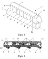
- FIG. 1 shows the air intake duct system 1 according to the invention.
- An intake pipe 2 has an inlet flow path 3, of which two to each cylinder is not branch individual engine channels 4, 5, shown. Thereby owns each individual channel 4 has a swirl flap 6 (see FIG. 2) for optimizing the inlet flow in relation to the operating range or the speed.
- the swirl flaps in carrier elements 7 are on one Housing part 8 arranged.
- the housing part is 8 completed by a welded-on cover element 9.
- a Plug element 10 shown for the electrical connection of the drive 11.
- Die Carrier elements 7 extend into slot-shaped recesses 12, which are in the individual channels 4 are attached.
- Fig. 2 shows the opened housing part 8 with those arranged on the underside Carrier elements 7 and the swirl flaps stored therein 6.
- a first gear 14 is again with a gear rod 15 in engagement, which in turn drives the gears 16.
- end position switches 17 are provided for the closed and open positions of the swirl flaps.
- the carrier elements 7 by clip elements 18 with the Housing part 8 clipped.
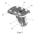
- Fig. 3 shows the carrier element 7 in a perspective individual view.
- the clip elements 18 with which the carrier element 7 on the housing part 8 can be seen is attached.
- a coupling element 19 is shown on the one hand the swirl flap 6 and on the other hand with the gears 14, 16 is engaged.
- the circumferential sealing ring 20 seals the carrier element 7 from the housing part 8.
- a contact surface 21 of the carrier element 7 directed towards the housing part 8 can be seen in FIG Relative to the axis of rotation 8 be carried out asymmetrically. That way it is possible the swirl flaps 6 different cylinder distances of the internal combustion engine thereby adapt that the carrier elements 7 either with the axis of rotation inwards or used in the housing part 8 directed outwards.
- the carrier element 7 and the housing part 8 of course also could be made in one piece.
- the clip elements 18 and the circumferential Sealing ring 20 is omitted in this case.
Landscapes
- Engineering & Computer Science (AREA)
- Chemical & Material Sciences (AREA)
- Combustion & Propulsion (AREA)
- Mechanical Engineering (AREA)
- General Engineering & Computer Science (AREA)
- Characterised By The Charging Evacuation (AREA)
- Cylinder Crankcases Of Internal Combustion Engines (AREA)
Abstract
Description
Auch ist es möglich, dass die Trägerelemente und das Gehäuseteil aus einem Stück gefertigt sind. Darüber hinaus ist es vorteilhaft, wenn dass Gehäuseteil, die Drallklappen, die Trägerelemente und die Zahnräder Kunststoffspritzteile sind.
- Fig. 1
- das erfindungsgemäße Luftansaugkanalsystem mit geöffnetem Gehäuseteil in einer perspektivischen Ansicht,
- Fig.2
- eine perspektivische Ansicht des geöffneten Gehäuseteils mit angeklipsten Trägerelementen und
- Fig.3
- eine perspektivische Ansicht des Trägerelementes mit eingesetzter Drallklappe.
Claims (6)
- Luftansaugkanalsystem für eine Brennkraftmaschine mit einem Saugrohr, das zwei zu jedem Zylinder der Brennkraftmaschine führende Einzelkanäle aufweist, die sich von einem gemeinsamen Einlaßströmungsweg abzweigen, wobei jeweils einer der beiden Einzelkanäle eine Drallklappe aufweist, die in einem Trägerelement gelagert ist, dadurch gekennzeichnet, dass die Trägerelemente (7) an einem Gehäuseteil (8) angeordnet sind, wobei in dem Gehäuseteil (8) ein Antrieb (11) und ein Antriebsmechanismus (13, 14, 15, 16) zur Verstellung der Drallklappen (6) gelagert sind und das Saugrohr (2) quer zu den Einzelkanälen (4, 5) verlaufende schlitzförmige Aussparungen (12) aufweist, derart, dass wenn das Gehäuseteil (8) auf dem Saugrohr (2) befestigt ist, die Trägerelemente (7) in die entsprechenden schlitzförmigen Aussparungen eingreifen.
- Luftansaugkanalsystem nach Anspruch 1, dadurch gekennzeichnet, dass der Antrieb (11) ein Elektromotor ist, der über eine Zahnstange (15) und in dem Gehäuseteil (8) gelagerten Zahnräder (14, 16) die Drallklappen (6) antreibt.
- Luftansaugkanalsystem nach Anspruch 1 oder 2, dadurch gekennzeichnet, dass das Gehäuseteil (8) mit dem Saugrohr (2) verklipst oder verschraubt ist.
- Luftansaugkanalsystem nach einem der vorhergehenden Ansprüche, dadurch gekennzeichnet, dass eine zum Gehäuseteil (8) gerichtete Anlagefläche (21) des Trägerelementes (7) in Bezug auf die Drehachse (22) der Drallklappe (6) in Längsrichtung des Gehäuseteils (8) asymmetrisch ausgeführt ist.
- Luftansaugkanalsystem nach einem der vorhergehenden Ansprüche, dadurch gekennzeichnet, dass die Trägerelemente (7) und das Gehäuseteil (8) aus einem Stück gefertigt sind.
- Luftansaugkanalsystem nach einem der vorhergehenden Ansprüche, dadurch gekennzeichnet, dass das Gehäuseteil (8), die Drallklappen (6), die Trägerelemente (7) und die Zahnräder (14, 16) Kunststoffspritzteile sind.
Applications Claiming Priority (2)
| Application Number | Priority Date | Filing Date | Title |
|---|---|---|---|
| DE10005431 | 2000-02-08 | ||
| DE10005431A DE10005431A1 (de) | 2000-02-08 | 2000-02-08 | Luftansaugkanalsystem für eine Brennkraftmaschine |
Publications (2)
| Publication Number | Publication Date |
|---|---|
| EP1124043A1 true EP1124043A1 (de) | 2001-08-16 |
| EP1124043B1 EP1124043B1 (de) | 2002-07-03 |
Family
ID=7630158
Family Applications (1)
| Application Number | Title | Priority Date | Filing Date |
|---|---|---|---|
| EP01100415A Expired - Lifetime EP1124043B1 (de) | 2000-02-08 | 2001-01-08 | Luftansaugkanalsystem für eine Brennkraftmaschine |
Country Status (2)
| Country | Link |
|---|---|
| EP (1) | EP1124043B1 (de) |
| DE (2) | DE10005431A1 (de) |
Families Citing this family (1)
| Publication number | Priority date | Publication date | Assignee | Title |
|---|---|---|---|---|
| DE102013101938B4 (de) | 2013-02-27 | 2020-02-13 | Pierburg Gmbh | Antriebsanordnung für ein Aggregat eines Verbrennungsmotors und Abgasrückführventil |
Citations (6)
| Publication number | Priority date | Publication date | Assignee | Title |
|---|---|---|---|---|
| JPS59192825A (ja) * | 1983-04-15 | 1984-11-01 | Toyota Motor Corp | インテークエアコントロールバルブ装置 |
| EP0480607A1 (de) * | 1990-10-12 | 1992-04-15 | Ford Motor Company Limited | Ladeansaugsystem einer Brennkraftmaschine |
| JPH08232668A (ja) * | 1995-02-27 | 1996-09-10 | Toyota Motor Corp | 内燃機関の吸気制御装置 |
| WO1996031692A1 (en) * | 1995-04-06 | 1996-10-10 | E.I. Du Pont De Nemours And Company | Resin air intake system provided with intake control valve |
| US5696318A (en) * | 1995-02-10 | 1997-12-09 | Filterwerk Mann & Hummel Gmbh | Air intake for an internal combustion engine |
| EP0861977A2 (de) * | 1997-02-26 | 1998-09-02 | Knecht Filterwerke Gmbh | Drosselklappen-Einrichtung für eine Saugrohranlage eines Verbrennungsmotors |
-
2000
- 2000-02-08 DE DE10005431A patent/DE10005431A1/de not_active Withdrawn
-
2001
- 2001-01-08 EP EP01100415A patent/EP1124043B1/de not_active Expired - Lifetime
- 2001-01-08 DE DE50100008T patent/DE50100008D1/de not_active Expired - Lifetime
Patent Citations (6)
| Publication number | Priority date | Publication date | Assignee | Title |
|---|---|---|---|---|
| JPS59192825A (ja) * | 1983-04-15 | 1984-11-01 | Toyota Motor Corp | インテークエアコントロールバルブ装置 |
| EP0480607A1 (de) * | 1990-10-12 | 1992-04-15 | Ford Motor Company Limited | Ladeansaugsystem einer Brennkraftmaschine |
| US5696318A (en) * | 1995-02-10 | 1997-12-09 | Filterwerk Mann & Hummel Gmbh | Air intake for an internal combustion engine |
| JPH08232668A (ja) * | 1995-02-27 | 1996-09-10 | Toyota Motor Corp | 内燃機関の吸気制御装置 |
| WO1996031692A1 (en) * | 1995-04-06 | 1996-10-10 | E.I. Du Pont De Nemours And Company | Resin air intake system provided with intake control valve |
| EP0861977A2 (de) * | 1997-02-26 | 1998-09-02 | Knecht Filterwerke Gmbh | Drosselklappen-Einrichtung für eine Saugrohranlage eines Verbrennungsmotors |
Non-Patent Citations (2)
| Title |
|---|
| PATENT ABSTRACTS OF JAPAN vol. 009, no. 057 (M - 363) 13 March 1985 (1985-03-13) * |
| PATENT ABSTRACTS OF JAPAN vol. 1997, no. 01 31 January 1997 (1997-01-31) * |
Also Published As
| Publication number | Publication date |
|---|---|
| DE10005431A1 (de) | 2001-08-09 |
| EP1124043B1 (de) | 2002-07-03 |
| DE50100008D1 (de) | 2002-08-08 |
Similar Documents
| Publication | Publication Date | Title |
|---|---|---|
| EP0717815B1 (de) | Drosseleinrichtung | |
| EP0726388B1 (de) | Ansaugsystem | |
| EP0725210B1 (de) | Saugmodul | |
| DE69609319T2 (de) | Kunststoff luftansaugsystem mit einlassteuerventil | |
| DE3432047A1 (de) | Zweitaktmaschine | |
| DE19614474B4 (de) | Luftansaugkanalsystem für Brennkraftmaschinen | |
| EP0970301B1 (de) | Schaltwal einer saugrohranlage für eine mehrzylinder-brennkraftmaschine | |
| DE19621221A1 (de) | Aggregat und Schnappvorrichtung für ein Aggregat | |
| EP1156200B1 (de) | Klappenstelleinheit | |
| EP0480393A1 (de) | Brennkraftmaschine mit einem zylindrischen Schieber | |
| DE19919533A1 (de) | Einlassleitungsanordnung für eine Brennkraftmaschine | |
| EP1085197B1 (de) | Luftansaugkanalsystem für Brennkraftmaschinen | |
| EP1124043B1 (de) | Luftansaugkanalsystem für eine Brennkraftmaschine | |
| EP1136689B1 (de) | Fördereinrichtung zum Fördern von Kraftstoff | |
| EP1241344A2 (de) | Luftansaugkanalsystem für eine Brennkraftmaschine | |
| EP1223331B1 (de) | Abgasrückführeinrichtung für eine Brennkraftmaschine | |
| EP1422413A2 (de) | Ansaugsystem | |
| DE69910269T2 (de) | Brennkraftmaschine mit einer kompakten Ansaugeinrichtung | |
| EP1388652B1 (de) | Ansaugkanalsystem | |
| DE10106364B4 (de) | Vergaseranordnung mit einem Choke-Element | |
| DE102004002641B4 (de) | Modulare Ansaugvorrichtung | |
| DE19651642A1 (de) | Lufteinlaßkanalsystem für Brennkraftmaschinen | |
| EP1020635B1 (de) | Brennluftansaugrohrabschnitt für Dieselbrennkraftmaschinen | |
| DE19728078C2 (de) | Vorrichtung zum Ansaugen von Luft | |
| AT3136U1 (de) | Einlasssystem mit einer einlassrohrverzweigung für eine brennkraftmaschine mit mehreren zylindern |
Legal Events
| Date | Code | Title | Description |
|---|---|---|---|
| PUAI | Public reference made under article 153(3) epc to a published international application that has entered the european phase |
Free format text: ORIGINAL CODE: 0009012 |
|
| 17P | Request for examination filed |
Effective date: 20010108 |
|
| AK | Designated contracting states |
Kind code of ref document: A1 Designated state(s): DE FR GB IT SE |
|
| AX | Request for extension of the european patent |
Free format text: AL;LT;LV;MK;RO;SI |
|
| GRAG | Despatch of communication of intention to grant |
Free format text: ORIGINAL CODE: EPIDOS AGRA |
|
| GRAG | Despatch of communication of intention to grant |
Free format text: ORIGINAL CODE: EPIDOS AGRA |
|
| GRAH | Despatch of communication of intention to grant a patent |
Free format text: ORIGINAL CODE: EPIDOS IGRA |
|
| 17Q | First examination report despatched |
Effective date: 20011204 |
|
| GRAH | Despatch of communication of intention to grant a patent |
Free format text: ORIGINAL CODE: EPIDOS IGRA |
|
| AKX | Designation fees paid |
Free format text: DE FR GB IT SE |
|
| GRAA | (expected) grant |
Free format text: ORIGINAL CODE: 0009210 |
|
| AK | Designated contracting states |
Kind code of ref document: B1 Designated state(s): DE FR GB IT SE |
|
| RAP2 | Party data changed (patent owner data changed or rights of a patent transferred) |
Owner name: PIERBURG GMBH |
|
| REF | Corresponds to: |
Ref document number: 50100008 Country of ref document: DE Date of ref document: 20020808 |
|
| GBT | Gb: translation of ep patent filed (gb section 77(6)(a)/1977) |
Effective date: 20020918 |
|
| ET | Fr: translation filed | ||
| PLBE | No opposition filed within time limit |
Free format text: ORIGINAL CODE: 0009261 |
|
| STAA | Information on the status of an ep patent application or granted ep patent |
Free format text: STATUS: NO OPPOSITION FILED WITHIN TIME LIMIT |
|
| 26N | No opposition filed |
Effective date: 20030404 |
|
| PGFP | Annual fee paid to national office [announced via postgrant information from national office to epo] |
Ref country code: SE Payment date: 20060112 Year of fee payment: 6 |
|
| PG25 | Lapsed in a contracting state [announced via postgrant information from national office to epo] |
Ref country code: SE Free format text: LAPSE BECAUSE OF NON-PAYMENT OF DUE FEES Effective date: 20070109 |
|
| EUG | Se: european patent has lapsed | ||
| GBPC | Gb: european patent ceased through non-payment of renewal fee |
Effective date: 20070108 |
|
| PG25 | Lapsed in a contracting state [announced via postgrant information from national office to epo] |
Ref country code: GB Free format text: LAPSE BECAUSE OF NON-PAYMENT OF DUE FEES Effective date: 20070108 |
|
| PGFP | Annual fee paid to national office [announced via postgrant information from national office to epo] |
Ref country code: GB Payment date: 20060120 Year of fee payment: 6 |
|
| PGFP | Annual fee paid to national office [announced via postgrant information from national office to epo] |
Ref country code: FR Payment date: 20100209 Year of fee payment: 10 Ref country code: IT Payment date: 20100123 Year of fee payment: 10 |
|
| REG | Reference to a national code |
Ref country code: FR Ref legal event code: ST Effective date: 20110930 |
|
| PG25 | Lapsed in a contracting state [announced via postgrant information from national office to epo] |
Ref country code: FR Free format text: LAPSE BECAUSE OF NON-PAYMENT OF DUE FEES Effective date: 20110131 |
|
| PG25 | Lapsed in a contracting state [announced via postgrant information from national office to epo] |
Ref country code: IT Free format text: LAPSE BECAUSE OF NON-PAYMENT OF DUE FEES Effective date: 20110108 |
|
| PGFP | Annual fee paid to national office [announced via postgrant information from national office to epo] |
Ref country code: DE Payment date: 20120321 Year of fee payment: 12 |
|
| PG25 | Lapsed in a contracting state [announced via postgrant information from national office to epo] |
Ref country code: DE Free format text: LAPSE BECAUSE OF NON-PAYMENT OF DUE FEES Effective date: 20130801 |
|
| REG | Reference to a national code |
Ref country code: DE Ref legal event code: R119 Ref document number: 50100008 Country of ref document: DE Effective date: 20130801 |