EP1123893A1 - Crane - Google Patents
Crane Download PDFInfo
- Publication number
- EP1123893A1 EP1123893A1 EP01200449A EP01200449A EP1123893A1 EP 1123893 A1 EP1123893 A1 EP 1123893A1 EP 01200449 A EP01200449 A EP 01200449A EP 01200449 A EP01200449 A EP 01200449A EP 1123893 A1 EP1123893 A1 EP 1123893A1
- Authority
- EP
- European Patent Office
- Prior art keywords
- jib
- cable
- crane
- guide
- hoisting cable
- Prior art date
- Legal status (The legal status is an assumption and is not a legal conclusion. Google has not performed a legal analysis and makes no representation as to the accuracy of the status listed.)
- Granted
Links
- XAGFODPZIPBFFR-UHFFFAOYSA-N aluminium Chemical compound [Al] XAGFODPZIPBFFR-UHFFFAOYSA-N 0.000 claims description 3
- 229910052782 aluminium Inorganic materials 0.000 claims description 3
- 239000004411 aluminium Substances 0.000 claims description 3
- 229910000831 Steel Inorganic materials 0.000 claims description 2
- 239000010959 steel Substances 0.000 claims description 2
- 229920002994 synthetic fiber Polymers 0.000 claims description 2
- 239000000463 material Substances 0.000 description 3
- 238000010276 construction Methods 0.000 description 2
- 230000000694 effects Effects 0.000 description 1
- 230000005484 gravity Effects 0.000 description 1
- 238000009434 installation Methods 0.000 description 1
- 238000004519 manufacturing process Methods 0.000 description 1
- 238000004804 winding Methods 0.000 description 1
Images


Classifications
-
- B—PERFORMING OPERATIONS; TRANSPORTING
- B66—HOISTING; LIFTING; HAULING
- B66C—CRANES; LOAD-ENGAGING ELEMENTS OR DEVICES FOR CRANES, CAPSTANS, WINCHES, OR TACKLES
- B66C23/00—Cranes comprising essentially a beam, boom, or triangular structure acting as a cantilever and mounted for translatory of swinging movements in vertical or horizontal planes or a combination of such movements, e.g. jib-cranes, derricks, tower cranes
- B66C23/62—Constructional features or details
- B66C23/64—Jibs
- B66C23/70—Jibs constructed of sections adapted to be assembled to form jibs or various lengths
- B66C23/701—Jibs constructed of sections adapted to be assembled to form jibs or various lengths telescopic
-
- B—PERFORMING OPERATIONS; TRANSPORTING
- B60—VEHICLES IN GENERAL
- B60P—VEHICLES ADAPTED FOR LOAD TRANSPORTATION OR TO TRANSPORT, TO CARRY, OR TO COMPRISE SPECIAL LOADS OR OBJECTS
- B60P1/00—Vehicles predominantly for transporting loads and modified to facilitate loading, consolidating the load, or unloading
- B60P1/54—Vehicles predominantly for transporting loads and modified to facilitate loading, consolidating the load, or unloading using cranes for self-loading or self-unloading
-
- B—PERFORMING OPERATIONS; TRANSPORTING
- B66—HOISTING; LIFTING; HAULING
- B66C—CRANES; LOAD-ENGAGING ELEMENTS OR DEVICES FOR CRANES, CAPSTANS, WINCHES, OR TACKLES
- B66C11/00—Trolleys or crabs, e.g. operating above runways
- B66C11/16—Rope, cable, or chain drives for trolleys; Combinations of such drives with hoisting gear
Definitions
- the present invention relates to a crane, comprising a hoisting cable, an outer jib and at least one inner jib, which can travel laterally in the outer jib between a first, essentially retracted position and a second, at least partly extended position, where the inner jib can be extracted from the outer jib via a first end of the outer jib and where at the crane a reel is provided for receiving the hoisting cable.
- Such a crane is known from U.S. Patent 4,187,048.
- a crane is described, which can travel from a retracted position to an extended position by means of an extending inner jib.
- a cable reel with a cable At the most extended end of the inner jib is connected a cable reel with a cable, by means of which a load can be lifted, respectively lowered.
- this crane its mounting in a vehicle is mentioned.
- the cable reel including the hoisting mechanism is carried out as a whole, a relatively large vertical volume of the vehicle is used up by the crane.
- the purpose of the present invention is especially to provide a crane which takes up less space than the known crane.
- the purpose is also to provide a crane which is simple to operate and with which loads can be placed in a vehicle or the like in a simple way. Besides application in vehicles, it must also be possible for the crane to be used in, for example, boats.
- the reel is connected at or near a second end of the outer jib
- the inner jib comprises at its end which can extend outwards a guide for guiding the hoisting cable
- the hoisting cable is guided via the guide over a cable pulley which is connected to a traveller which can travel in the longitudinal direction of the inner jib, and in that the traveller is connected via a second cable or the like with the outer jib, which cable is guided via a second guide connected to the end which is directed inwards of the inner jib, in such a way that when the inner jib travels in the outer jib from the first, respectively the second position, to the second, respectively the first position, the vertical position of the end of the hoisting cable remains constant and simultaneously the traveller in the inner jib travels from the one end to the other end.
- the crane according to the invention has the advantage that it takes up only very little vertical space. This is achieved in particular in that the reel with which the hoisting cable can be raised and lowered, does not necessarily have to be attached to the jib any more. Instead of a position at or near an end of the outer jib, it is also possible to attach the reel in a position further away from the jib; in the case of a vehicle for example near a side exit of the vehicle. In the event of an electrically operated reel, the operating panel for the reel can be mounted near an exit of the vehicle or possibly even separately on the outside of the vehicle, and the reel can be located in an arbitrary suitable place inside the vehicle.
- the crane according to the invention can be made of any suitable material.
- the jibs for example can be made of aluminium or of fibre-reinforced synthetic material, which has the major advantage that the weight thereof can be kept relatively low. It is also possible to make for example the outer jib of a suitable type of steel, and the inner jib of aluminium.
- the surfaces for the lateral movement of the jib may be made of a suitable, wear-proof material.
- the inner jib can move through the outer jib in a sliding way. It is also possible to let the inner jib travel over a suitable surface of the outer jib by means of roller wheels, or vice versa, in which case the roller wheels are located in the outer jib.
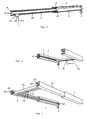
- Figure 1 shows a longitudinal section of a crane according to the present invention in a first position.
- Figure 2 shows a longitudinal section of a crane according to the present invention in a second position.
- Figure 3 shows a longitudinal section of a crane according to the present invention in accordance with a second embodiment in a first position.
- Figure 4 shows a longitudinal section of a device according to the present invention in accordance with a second embodiment in a second position.
- Figure 5 shows a perspective view of a crane according to the present invention in accordance with the first embodiment.
- Figure 6 shows a perspective view of a crane according to the present invention in accordance with a third embodiment in a first position.
- Figure 7 shows a perspective view of a crane according to the present invention in accordance with a third embodiment in a second position.
- the crane 1 comprises an outer jib 3 and an inner jib 4, as shown in figures 1 and 2.
- the inner jib 4 is mounted in a laterally moving way in the outer jib 3.
- a hoisting cable 2 is provided which in the embodiment shown in figures 1 and 2 is equipped with a fastening means 2A.
- the hoisting cable is connected with a reel 7, which in the embodiment shown is mounted near an end 6 of the outer jib 3.
- Fig. 5 shows a perspective view where the reel 7 is mounted outside the end of the outer jib 3.
- the inner jib is shown in fig.
- fig. 2 shows the situation in which the inner jib is in the most extended position.
- the hoisting cable is guided from the reel 7 over a guide 9, which is fastened at the end 8 of the inner jib 4.
- the hoisting cable 2 is then guided back to a traveller 11, and is guided via a cable pulley 10, after which the hoisting cable hangs down vertically.
- the traveller 11 is connected via a second cable 12 or the like with the outer jib 3.
- this second cable 12 or the like is guided via a guide 14, which guide 14 is fastened to the other end of the inner jib 4.
- this second cable 12 or the like is guided back via this second guide 14 and is fastened to the foremost end of the outer jib 3.
- this second cable 12 has a fixed position and is connected at its other end with the end 5 of the outer jib 3, and the hoisting cable 2 is secured to the reel 7, the end of the hoisting cable 2 and the load hanging from the fastening means 2A will remain in a fixed vertical position when the inner jib 4 travels in the lateral direction through the outer jib 3.
- the traveller 11 When the inner jib 4 is moved from a most retracted position in the outer jib 3 to a most extended position in the outer jib 3, the traveller 11 will be moved from a most right-hand position (see Fig. 1) to a most left-hand position (see Fig. 2), as this traveller 11 is connected via the cable 12 with the outer jib 3.
- the traveller 11 will therefore cover a distance, when the inner jib 4 is extended, which amounts to twice the extended length of the inner jib. In this way a load can be moved over a great distance without a large construction being required.
- the construction can be realised in such a way that the inner jib 4 and thus the traveller 11 can be moved manually in the horizontal direction.
- an auxiliary system for example a hydraulic system, to let the inner jib retract and/or extend.
- the traveller 11 can travel over the length of the inner jib 4, for example by means of roller wheels. These roller wheels may be guided over guidance paths which have been mounted on the inner jib 4. These guidance devices are not shown in figures 1 and 2.
- the cable 12 may also consist of a chain.
- the guide 14 may consists for example of a gearwheel. It is also possible, however, that the cable 12 consists of something else than a chain, for example a belt-shaped or ribbon-shaped connecting means.
- Figures 3 and 4 show a second embodiment of the present invention.
- the crane 1 consists of an outer jib 3 and two inner jibs 4 and 15.
- Fig. 3 shows the crane in a first, most retracted position, in which the fastening means and the load hanging therefrom are located near the end 5 of the outer jib 3.
- Fig. 4 shows the crane 1 in a second, most extended position, in which the load is located near the end 8 of the inner jib 4. In this position the inner jib 15 is extended almost entirely from the outer jib 3 and the inner jib 4 is extended almost entirely from the inner jib 15.
- the load has travelled in the movement from the first to the second position a distance which equals the sum of the extended lengths of the two inner jibs 4 and 15.
- the hoisting cable 2 is guided from the reel 7 over a guide 19 which is connected with the end 18 of the inner jib 15, is then guided further over a guide 17 which is connected with the inner end 13 of the inner jib 4 and finally over a guide 9 which is located near the outer end 8 of the inner jib 4.
- the inner end 13 of the inner jib 4 is connected by means of a cable 12 or the like via guide 14 in the inner end 16 of the inner jib 15 with the outer end 5 of the outer jib 3.
- Such a system of guides and cables as shown assures that the load will always continue to hang in the same vertical position when the inner jibs are extended from or retracted into the outer jib.
- the cable 12 or the like in a closed system, as described above with reference to figures 1 and 2.
- the cable 12 is extended from the inner end 13 of the inner jib 4 and is guided over a guide 25 (shown in figures 3 and 4 by means of a dotted line), which is mounted in the outer end 18 of the inner jib 15, and is then connected with the outer end 5 of the outer jib 3, for example near the other end of the cable 12.
- FIGS 6 and 7 show a third embodiment of the invention, where a first position and a second position, respectively, are shown. It can be seen clearly in these figures that the reel 7 is fastened in a position under the outer jib. To that end an extra guide 20 has been provided near the end 6 of the outer jib 3.
- the crane comprises two sets, placed in parallel, consisting each of an outer jib and an inner jib, whereas a cross-beam 21 has been provided (perpendicular in the embodiment shown, but that is not necessary) between these two sets. This crossbeam 21 fulfils the role of the traveller 11 as shown in figures 1 to 4 inclusive.
- the crossbeam 21 will move from a hindmost position to a frontmost position.
- the crossbeam 21 can be guided for example by means of roller wheels (not shown) over the guidance surfaces 22, 23 on the inside of the inner jib 4. These roller wheels (not shown) can be guided over the guidance surfaces 22 as well as over the guidance surfaces 23.
- the cable pulley 24, which is mounted in the crossbeam 21 has been mounted in a fixed position. It is also possible however, according to an alternative embodiment, to mount it in a mobile way over the length of the crossbeam 21. In that case it is possible to position a load to be moved in a two-dimensional direction.
- the crane according to the present invention can be used in many places, for example in vehicles, boats and the like. It is also possible to realise the crane as a mobile installation, which can be set up for example (for the purpose for removals or for moving large and heavy objects) in dwellings, for example by including the crane in a separate frame.
- the frame may in that case be fastened to a floor or be clamped between a floor and a ceiling, the crane being located near a window opening.
- the crane according to this invention with opened windows, to hoist and move into the dwelling loads that are located outside the building on the ground floor.
- the great advantage of the crane according to the invention in such an application is that the crane can be set up on any floor and in any room where there is a window.
Landscapes
- Engineering & Computer Science (AREA)
- Mechanical Engineering (AREA)
- Transportation (AREA)
- Jib Cranes (AREA)
- Iron Core Of Rotating Electric Machines (AREA)
Abstract
Description
- The present invention relates to a crane, comprising a hoisting cable, an outer jib and at least one inner jib, which can travel laterally in the outer jib between a first, essentially retracted position and a second, at least partly extended position, where the inner jib can be extracted from the outer jib via a first end of the outer jib and where at the crane a reel is provided for receiving the hoisting cable.
- Such a crane is known from U.S. Patent 4,187,048. In this patent a crane is described, which can travel from a retracted position to an extended position by means of an extending inner jib. At the most extended end of the inner jib is connected a cable reel with a cable, by means of which a load can be lifted, respectively lowered. As possible application of this crane, its mounting in a vehicle is mentioned. As the cable reel including the hoisting mechanism is carried out as a whole, a relatively large vertical volume of the vehicle is used up by the crane.
- The known crane as described in said U.S. Patent Specification takes up a lot a space as one whole. As a small volume of the crane is important, especially when used in a vehicle, this known crane has never been applied on a large scale.
- It is the purpose of the present invention to provide an improved crane. The purpose is especially to provide a crane which takes up less space than the known crane. The purpose is also to provide a crane which is simple to operate and with which loads can be placed in a vehicle or the like in a simple way. Besides application in vehicles, it must also be possible for the crane to be used in, for example, boats.
- The advantages described above are obtained by means of a crane as described in the preamble, and which is characterised in that the reel is connected at or near a second end of the outer jib, in that the inner jib comprises at its end which can extend outwards a guide for guiding the hoisting cable, in that the hoisting cable is guided via the guide over a cable pulley which is connected to a traveller which can travel in the longitudinal direction of the inner jib, and in that the traveller is connected via a second cable or the like with the outer jib, which cable is guided via a second guide connected to the end which is directed inwards of the inner jib, in such a way that when the inner jib travels in the outer jib from the first, respectively the second position, to the second, respectively the first position, the vertical position of the end of the hoisting cable remains constant and simultaneously the traveller in the inner jib travels from the one end to the other end.
- The crane according to the invention has the advantage that it takes up only very little vertical space. This is achieved in particular in that the reel with which the hoisting cable can be raised and lowered, does not necessarily have to be attached to the jib any more. Instead of a position at or near an end of the outer jib, it is also possible to attach the reel in a position further away from the jib; in the case of a vehicle for example near a side exit of the vehicle. In the event of an electrically operated reel, the operating panel for the reel can be mounted near an exit of the vehicle or possibly even separately on the outside of the vehicle, and the reel can be located in an arbitrary suitable place inside the vehicle.
- The crane according to the invention can be made of any suitable material. The jibs for example can be made of aluminium or of fibre-reinforced synthetic material, which has the major advantage that the weight thereof can be kept relatively low. It is also possible to make for example the outer jib of a suitable type of steel, and the inner jib of aluminium. The surfaces for the lateral movement of the jib may be made of a suitable, wear-proof material.
- The inner jib can move through the outer jib in a sliding way. It is also possible to let the inner jib travel over a suitable surface of the outer jib by means of roller wheels, or vice versa, in which case the roller wheels are located in the outer jib.
- The invention will now be explained in greater detail with reference to the enclosed drawings.
- Figure 1 shows a longitudinal section of a crane according to the present invention in a first position.
- Figure 2 shows a longitudinal section of a crane according to the present invention in a second position.
- Figure 3 shows a longitudinal section of a crane according to the present invention in accordance with a second embodiment in a first position.
- Figure 4 shows a longitudinal section of a device according to the present invention in accordance with a second embodiment in a second position.
- Figure 5 shows a perspective view of a crane according to the present invention in accordance with the first embodiment.
- Figure 6 shows a perspective view of a crane according to the present invention in accordance with a third embodiment in a first position.
- Figure 7 shows a perspective view of a crane according to the present invention in accordance with a third embodiment in a second position.
- The
crane 1 according to the present invention comprises anouter jib 3 and aninner jib 4, as shown in figures 1 and 2. Theinner jib 4 is mounted in a laterally moving way in theouter jib 3. In order to be able to lift a load, i.e. move it in the vertical direction, a hoistingcable 2 is provided which in the embodiment shown in figures 1 and 2 is equipped with afastening means 2A. At its other end the hoisting cable is connected with areel 7, which in the embodiment shown is mounted near anend 6 of theouter jib 3. Fig. 5 shows a perspective view where thereel 7 is mounted outside the end of theouter jib 3. The inner jib is shown in fig. 1 in the most retracted position, whereas fig. 2 shows the situation in which the inner jib is in the most extended position. As the figures clearly show, the hoisting cable is guided from thereel 7 over aguide 9, which is fastened at theend 8 of theinner jib 4. The hoistingcable 2 is then guided back to atraveller 11, and is guided via acable pulley 10, after which the hoisting cable hangs down vertically. It can also be derived clearly from the figures that thetraveller 11 is connected via asecond cable 12 or the like with theouter jib 3. To that end thissecond cable 12 or the like is guided via aguide 14, whichguide 14 is fastened to the other end of theinner jib 4. To that end thissecond cable 12 or the like is guided back via thissecond guide 14 and is fastened to the foremost end of theouter jib 3. - It appears clearly from figures 1 and 2, that when the
inner jib 4 travels out of theouter jib 3, the entire assembly ofinner jib 4,guide 9, andguide 14, is extended via theend 5 out of theouter jib 3. The hindmost end (in the figures the most right-hand part) of theinner jib 4 will remain behind in theouter jib 3, to provide the stability required. As the traveller is connected with the hoistingcable 2 as well as with thesecond cable 12 or the like, and thissecond cable 12 has a fixed position and is connected at its other end with theend 5 of theouter jib 3, and the hoistingcable 2 is secured to thereel 7, the end of the hoistingcable 2 and the load hanging from thefastening means 2A will remain in a fixed vertical position when theinner jib 4 travels in the lateral direction through theouter jib 3. In this way it is possible to mount the reel, or any other winding means for the hoistingcable 2, not at or near the inner jib, but in a quite different position, so that the moment on the end of the inner jib 4 (or another position from where the hoistingcable 2 hangs down) is reduced, whereas, in addition, the advantage is obtained that the vertical height near the hoisting position, which is, at a fully extended inner jib, the end of thecrane 1, is reduced strongly. In the embodiment shown thereel 7 is located at the end of theouter jib 3, but obviously it is also possible to place the reel outside the outer jib. - When the
inner jib 4 is moved from a most retracted position in theouter jib 3 to a most extended position in theouter jib 3, thetraveller 11 will be moved from a most right-hand position (see Fig. 1) to a most left-hand position (see Fig. 2), as thistraveller 11 is connected via thecable 12 with theouter jib 3. Thetraveller 11 will therefore cover a distance, when theinner jib 4 is extended, which amounts to twice the extended length of the inner jib. In this way a load can be moved over a great distance without a large construction being required. Besides, the construction can be realised in such a way that theinner jib 4 and thus thetraveller 11 can be moved manually in the horizontal direction. In the event of heavier loads use can be made, if necessary, of an auxiliary system, for example a hydraulic system, to let the inner jib retract and/or extend. - The
traveller 11 can travel over the length of theinner jib 4, for example by means of roller wheels. These roller wheels may be guided over guidance paths which have been mounted on theinner jib 4. These guidance devices are not shown in figures 1 and 2. - The
cable 12 may also consist of a chain. In that case theguide 14 may consists for example of a gearwheel. It is also possible, however, that thecable 12 consists of something else than a chain, for example a belt-shaped or ribbon-shaped connecting means. - If no vertical force is exercised on the hoisting
cable 2 by a load, it is possible that because of the weight of the cable 12 (for example a chain 12), this chain will descend slightly, as a result of the effect of gravity on thechain 12, so that thetraveller 11, including thecable pulley 10, will be pulled towards the right. This may be possible until the fastening means 2a which is fastened to the end of the hoistingcable 2 lies against thecable pulley 10 and/or thetraveller 11. To avoid this, it is possible to fasten thecable 12 or the like to thetraveller 11 and extend it from there and guide it further to a third guide 25 (shown in the figure with a dotted line) which is connected at or near theend 8 of theinner jib 4, to guide it around this end and then back to theend 5 of theouter jib 3, for example near the point where the other end of thecable 12 or the like is fastened to the outer jib. In that case a closed system of thecable 12 is obtained, so that it is impossible that it sags if no load is exercised downwards in the vertical direction on the hoistingcable 2. - Figures 3 and 4 show a second embodiment of the present invention. In this embodiment the
crane 1 consists of anouter jib 3 and twoinner jibs end 5 of theouter jib 3. Fig. 4 shows thecrane 1 in a second, most extended position, in which the load is located near theend 8 of theinner jib 4. In this position theinner jib 15 is extended almost entirely from theouter jib 3 and theinner jib 4 is extended almost entirely from theinner jib 15. The load has travelled in the movement from the first to the second position a distance which equals the sum of the extended lengths of the twoinner jibs cable 2 is guided from thereel 7 over aguide 19 which is connected with theend 18 of theinner jib 15, is then guided further over aguide 17 which is connected with theinner end 13 of theinner jib 4 and finally over aguide 9 which is located near theouter end 8 of theinner jib 4. Theinner end 13 of theinner jib 4 is connected by means of acable 12 or the like viaguide 14 in theinner end 16 of theinner jib 15 with theouter end 5 of theouter jib 3. Such a system of guides and cables as shown assures that the load will always continue to hang in the same vertical position when the inner jibs are extended from or retracted into the outer jib. - According to the embodiment as shown in figures 3 and 4 it is possible to include the
cable 12 or the like in a closed system, as described above with reference to figures 1 and 2. In that case thecable 12 is extended from theinner end 13 of theinner jib 4 and is guided over a guide 25 (shown in figures 3 and 4 by means of a dotted line), which is mounted in theouter end 18 of theinner jib 15, and is then connected with theouter end 5 of theouter jib 3, for example near the other end of thecable 12. - Other embodiments for guiding the hoisting
cable 2 and thecable 12, in order to achieve the intended goal of keeping constant the vertical position of the end of the hoistingcable 2, will be obvious to a man skilled in the art after reading this description. Also embodiments in which a traveller (as shown in figures 1 and 2) moves automatically from the one end to the other end of the inner jib at the extension and retraction of the inner jibs, will be obvious to the expert. - Figures 6 and 7 show a third embodiment of the invention, where a first position and a second position, respectively, are shown. It can be seen clearly in these figures that the
reel 7 is fastened in a position under the outer jib. To that end anextra guide 20 has been provided near theend 6 of theouter jib 3. In the embodiment of the invention shown in figures 6 and 7 the crane comprises two sets, placed in parallel, consisting each of an outer jib and an inner jib, whereas across-beam 21 has been provided (perpendicular in the embodiment shown, but that is not necessary) between these two sets. Thiscrossbeam 21 fulfils the role of thetraveller 11 as shown in figures 1 to 4 inclusive. At the movement of theinner jibs 4 out of theouter jib 3 from a most retracted position (as shown in figure 6) to a most extended position (as shown in figure 7), thecrossbeam 21 will move from a hindmost position to a frontmost position. Thecrossbeam 21 can be guided for example by means of roller wheels (not shown) over the guidance surfaces 22, 23 on the inside of theinner jib 4. These roller wheels (not shown) can be guided over the guidance surfaces 22 as well as over the guidance surfaces 23. In the embodiment shown, thecable pulley 24, which is mounted in thecrossbeam 21, has been mounted in a fixed position. It is also possible however, according to an alternative embodiment, to mount it in a mobile way over the length of thecrossbeam 21. In that case it is possible to position a load to be moved in a two-dimensional direction. - It is also possible to manufacture the embodiment as shown in figures 6 and 7 with two parallel sets of three jib sections, such as these have been described with reference to figures 3 and 4. In such an embodiment the
crossbeam 21 is connected in a rigid way with the twooutermost ends 8 of theinner jibs 4. - It will be obvious that various adjustments of the embodiments described above and shown in the drawings are possible without leaving the scope of the invention. Thus it is possible to apply the invention in a vertical crane, instead of a horizontal crane as shown in the figures. Vertical, extending cranes are generally known, but in all cases make use of hydraulics to extend the individual jibs. The use of a cable system according to the present invention results in a significant reduction of weight, so that such cranes can be built much lighter. It is also possible, therefore, to use smaller diameters of the individual jibs, at the same strength, by adjusting the material thickness to the strength desired.
- The crane according to the present invention can be used in many places, for example in vehicles, boats and the like. It is also possible to realise the crane as a mobile installation, which can be set up for example (for the purpose for removals or for moving large and heavy objects) in dwellings, for example by including the crane in a separate frame. The frame may in that case be fastened to a floor or be clamped between a floor and a ceiling, the crane being located near a window opening. In this way it is possible in a very simple way with the crane according to this invention, with opened windows, to hoist and move into the dwelling loads that are located outside the building on the ground floor. The great advantage of the crane according to the invention in such an application is that the crane can be set up on any floor and in any room where there is a window.
Claims (10)
- Crane (1), comprising a hoisting cable (2), an outer jib (3) and at least one inner jib (4), which can travel laterally in the outer jib between a first, essentially retracted position and a second, at least partly extended position, where the inner jib (4) can be extracted from the outer jib (3) via a first end (5) of the outer jib (3) and where at the crane a reel (7) is provided for receiving the hoisting cable (2), characterised in that the reel (7) is connected at or near a second end (6) of the outer jib (3), in that the inner jib (4) comprises at its end (8) which can extend outwards a guide (9) for guiding the hoisting cable, in that the hoisting cable (2) is guided via the guide (9) over a cable pulley (10) which is connected with a traveller (11) which can travel over the longitudinal direction of the inner jib (4), and in that the traveller (11) is connected via a second cable (12) or the like with the outer jib (3), which cable (12) is guided via a second guide (14) connected to the end (13) which is directed inwards of the inner jib (4), in such a way that when the inner jib (4) travels in the outer jib from the first, respectively the second, position to the second, respectively the first, position, the vertical position of the end of the hoisting cable (2) remains constant and simultaneously the traveller (11) in the inner jib (4) travels from the one end (13, respectively 8) to the other end (8, respectively 13).
- Crane according to claim 1, characterised in that the connection (12) comprises a chain and in that the guide (14) is a gearwheel.
- Crane according to claims 1 or 2, characterised in that the hoisting cable (2) is equipped at its end with a fastening means (2A).
- Crane according to any of the previous claims, characterised in that it is equipped with fastening means for fastening it to a vehicle or a boat.
- Crane according to any of the previous claims, which is equipped with three jibs retracting into one another (3, 4, 15), an outer jib (3) being as shown in claim 1, a second inner jib (15) being placed in a laterally sliding way in the outer jib and a first inner jib (4) being placed in a corresponding laterally sliding way in the second inner jib (15), a hoisting cable (2) being guided from a reel (7) over a guide (19) which is connected with the outermost end (18) of the inner jib (15), then over a guide (17) which is connected with the innermost end (13) of the inner jib (4) and finally over a guide (9) which is located near the outermost end (8) of the inner jib (4) and the innermost end (13) of the inner jib (4) being connected by means of a cable (12) or the like via a guide (14) in the innermost end (16) of the inner jib (15) with the outermost end (5) of the outer jib (3), in such a way that when the first inner jib (4) travels from a first, respectively second, position to a second, respectively first, position, the second inner jib (15) travels from a first, respectively second, position, to a second, respectively first, position and the vertical position of the hoisting cable (2) remains constant.
- Crane according to any of the previous claims, characterised in that one or several of the jibs are made of steel, aluminium or fibre-reinforced synthetic material, or a combination thereof.
- Crane according to any of the previous claims, which is equipped with two parallel sets consisting each of an outer jib and an inner jib according to claims 1-4, the traveller (11) consisting of one crossbeam (21), which is located between the two parallel inner jibs, this crossbeam (21) being equipped with a cable pulley (24) over which the hoisting cable (2) is guided with its end, and which can travel laterally in the inner jibs.
- Crane according to any of the previous claims, which is equipped with two parallel sets consisting each of one outer jib and at least two inner jibs according to claim 5, the traveller (11) consisting of a crossbeam, which is located between the two parallel inner jibs (4), this crossbeam (21) being equipped with a cable pulley (24) over which the hoisting cable (2) is guided with its end.
- Application of a crane according to any of the previous claims in a vertical hoisting crane.
- Application of a crane according to any of the claims 1-8 in a building.
Applications Claiming Priority (2)
| Application Number | Priority Date | Filing Date | Title |
|---|---|---|---|
| NL1014332A NL1014332C2 (en) | 2000-02-09 | 2000-02-09 | Hoisting device. |
| NL1014332 | 2000-02-09 |
Publications (2)
| Publication Number | Publication Date |
|---|---|
| EP1123893A1 true EP1123893A1 (en) | 2001-08-16 |
| EP1123893B1 EP1123893B1 (en) | 2004-09-29 |
Family
ID=19770778
Family Applications (1)
| Application Number | Title | Priority Date | Filing Date |
|---|---|---|---|
| EP01200449A Expired - Lifetime EP1123893B1 (en) | 2000-02-09 | 2001-02-09 | Crane |
Country Status (4)
| Country | Link |
|---|---|
| EP (1) | EP1123893B1 (en) |
| AT (1) | ATE277861T1 (en) |
| DE (1) | DE60105861T2 (en) |
| NL (1) | NL1014332C2 (en) |
Cited By (3)
| Publication number | Priority date | Publication date | Assignee | Title |
|---|---|---|---|---|
| EP1783090A1 (en) * | 2005-11-03 | 2007-05-09 | Michael Wolf | Lifting device |
| CN111731984A (en) * | 2020-05-26 | 2020-10-02 | 南京荣强仓储有限公司 | Lifting equipment for warehousing loading and unloading |
| CN117819411A (en) * | 2024-03-05 | 2024-04-05 | 沈阳露天采矿设备制造有限公司 | Cantilever type lifting telescopic beam device |
Citations (6)
| Publication number | Priority date | Publication date | Assignee | Title |
|---|---|---|---|---|
| DE193294C (en) * | ||||
| FR453260A (en) * | 1912-03-29 | 1913-06-04 | Societe De Construction Et De Location D Appareils | Load handling device |
| DE1175843B (en) * | 1960-11-19 | 1964-08-13 | Demag Ag | Loading bridge with cable drive for sliding carrier trolley |
| US3889818A (en) * | 1973-09-21 | 1975-06-17 | Carl G Wennerstrom | Extensible crane |
| EP0425389A2 (en) * | 1989-10-26 | 1991-05-02 | Hexatechnique S.A. | Handling apparatus and vehicle equipped with such an apparatus |
| US5743702A (en) * | 1996-05-03 | 1998-04-28 | Gunderson; Michael J. | Method and apparatus for a vehicle mounted hoisting system |
-
2000
- 2000-02-09 NL NL1014332A patent/NL1014332C2/en not_active IP Right Cessation
-
2001
- 2001-02-09 AT AT01200449T patent/ATE277861T1/en not_active IP Right Cessation
- 2001-02-09 EP EP01200449A patent/EP1123893B1/en not_active Expired - Lifetime
- 2001-02-09 DE DE60105861T patent/DE60105861T2/en not_active Expired - Lifetime
Patent Citations (6)
| Publication number | Priority date | Publication date | Assignee | Title |
|---|---|---|---|---|
| DE193294C (en) * | ||||
| FR453260A (en) * | 1912-03-29 | 1913-06-04 | Societe De Construction Et De Location D Appareils | Load handling device |
| DE1175843B (en) * | 1960-11-19 | 1964-08-13 | Demag Ag | Loading bridge with cable drive for sliding carrier trolley |
| US3889818A (en) * | 1973-09-21 | 1975-06-17 | Carl G Wennerstrom | Extensible crane |
| EP0425389A2 (en) * | 1989-10-26 | 1991-05-02 | Hexatechnique S.A. | Handling apparatus and vehicle equipped with such an apparatus |
| US5743702A (en) * | 1996-05-03 | 1998-04-28 | Gunderson; Michael J. | Method and apparatus for a vehicle mounted hoisting system |
Cited By (4)
| Publication number | Priority date | Publication date | Assignee | Title |
|---|---|---|---|---|
| EP1783090A1 (en) * | 2005-11-03 | 2007-05-09 | Michael Wolf | Lifting device |
| CN111731984A (en) * | 2020-05-26 | 2020-10-02 | 南京荣强仓储有限公司 | Lifting equipment for warehousing loading and unloading |
| CN117819411A (en) * | 2024-03-05 | 2024-04-05 | 沈阳露天采矿设备制造有限公司 | Cantilever type lifting telescopic beam device |
| CN117819411B (en) * | 2024-03-05 | 2024-05-14 | 沈阳露天采矿设备制造有限公司 | Cantilever type lifting telescopic beam device |
Also Published As
| Publication number | Publication date |
|---|---|
| ATE277861T1 (en) | 2004-10-15 |
| DE60105861D1 (en) | 2004-11-04 |
| EP1123893B1 (en) | 2004-09-29 |
| DE60105861T2 (en) | 2006-03-09 |
| NL1014332C2 (en) | 2001-08-13 |
Similar Documents
| Publication | Publication Date | Title |
|---|---|---|
| CN110023229B (en) | Elevator installation and method for building an elevator installation | |
| US11548762B2 (en) | Elevator car, elevator and method | |
| US5282663A (en) | Retracting system for flexible side walls for cargo vehicles | |
| RU2697969C2 (en) | Rescue elevator system | |
| US6041558A (en) | Collapsible tower system for antenna or the like | |
| CN102834342A (en) | Bridge crane | |
| DE102016108382B4 (en) | Rail profile for overhead crane lifts and slewing cranes with integrable energy chain | |
| EP2711324B1 (en) | An elevator arrangement and a method | |
| US5147051A (en) | Hoisting device for individuals | |
| EP1123893B1 (en) | Crane | |
| US4529062A (en) | Elevator system | |
| CN112645181A (en) | Well lift is used in construction | |
| CN210882124U (en) | Suspended train with escape device and suspended train system | |
| CN107337162A (en) | Height with horizontal displaceable reel cage can tap into workbench | |
| CN214569934U (en) | Well lift is used in construction | |
| US7341157B2 (en) | Enclosed-reeving, live-line boom | |
| CN111547604A (en) | Elevator device | |
| CN214359604U (en) | Elevator machine | |
| JPH085197Y2 (en) | Shuttle boom type jib crane | |
| AU2701399A (en) | Hydraulic elevator | |
| CN111377351A (en) | Crane for directly hoisting object into house | |
| KR102958388B1 (en) | Aerial Work Vehicle Boom Drive System | |
| JPH084415A (en) | Door device | |
| JP2875603B2 (en) | Lifting equipment for construction | |
| CN112645180A (en) | Construction hoistway double-car elevator and using method thereof |
Legal Events
| Date | Code | Title | Description |
|---|---|---|---|
| PUAI | Public reference made under article 153(3) epc to a published international application that has entered the european phase |
Free format text: ORIGINAL CODE: 0009012 |
|
| AK | Designated contracting states |
Kind code of ref document: A1 Designated state(s): AT BE CH CY DE DK ES FI FR GB GR IE IT LI LU MC NL PT SE TR |
|
| AX | Request for extension of the european patent |
Free format text: AL;LT;LV;MK;RO;SI |
|
| 17P | Request for examination filed |
Effective date: 20020109 |
|
| AKX | Designation fees paid |
Free format text: AT BE CH CY DE DK ES FI FR GB GR IE IT LI LU MC NL PT SE TR |
|
| 17Q | First examination report despatched |
Effective date: 20030423 |
|
| GRAP | Despatch of communication of intention to grant a patent |
Free format text: ORIGINAL CODE: EPIDOSNIGR1 |
|
| GRAS | Grant fee paid |
Free format text: ORIGINAL CODE: EPIDOSNIGR3 |
|
| GRAA | (expected) grant |
Free format text: ORIGINAL CODE: 0009210 |
|
| AK | Designated contracting states |
Kind code of ref document: B1 Designated state(s): AT BE CH CY DE DK ES FI FR GB GR IE IT LI LU MC NL PT SE TR |
|
| PG25 | Lapsed in a contracting state [announced via postgrant information from national office to epo] |
Ref country code: IT Free format text: LAPSE BECAUSE OF FAILURE TO SUBMIT A TRANSLATION OF THE DESCRIPTION OR TO PAY THE FEE WITHIN THE PRESCRIBED TIME-LIMIT;WARNING: LAPSES OF ITALIAN PATENTS WITH EFFECTIVE DATE BEFORE 2007 MAY HAVE OCCURRED AT ANY TIME BEFORE 2007. THE CORRECT EFFECTIVE DATE MAY BE DIFFERENT FROM THE ONE RECORDED. Effective date: 20040929 Ref country code: TR Free format text: LAPSE BECAUSE OF FAILURE TO SUBMIT A TRANSLATION OF THE DESCRIPTION OR TO PAY THE FEE WITHIN THE PRESCRIBED TIME-LIMIT Effective date: 20040929 Ref country code: LI Free format text: LAPSE BECAUSE OF FAILURE TO SUBMIT A TRANSLATION OF THE DESCRIPTION OR TO PAY THE FEE WITHIN THE PRESCRIBED TIME-LIMIT Effective date: 20040929 Ref country code: NL Free format text: LAPSE BECAUSE OF FAILURE TO SUBMIT A TRANSLATION OF THE DESCRIPTION OR TO PAY THE FEE WITHIN THE PRESCRIBED TIME-LIMIT Effective date: 20040929 Ref country code: AT Free format text: LAPSE BECAUSE OF FAILURE TO SUBMIT A TRANSLATION OF THE DESCRIPTION OR TO PAY THE FEE WITHIN THE PRESCRIBED TIME-LIMIT Effective date: 20040929 Ref country code: BE Free format text: LAPSE BECAUSE OF FAILURE TO SUBMIT A TRANSLATION OF THE DESCRIPTION OR TO PAY THE FEE WITHIN THE PRESCRIBED TIME-LIMIT Effective date: 20040929 Ref country code: ES Free format text: LAPSE BECAUSE OF FAILURE TO SUBMIT A TRANSLATION OF THE DESCRIPTION OR TO PAY THE FEE WITHIN THE PRESCRIBED TIME-LIMIT Effective date: 20040929 Ref country code: CH Free format text: LAPSE BECAUSE OF FAILURE TO SUBMIT A TRANSLATION OF THE DESCRIPTION OR TO PAY THE FEE WITHIN THE PRESCRIBED TIME-LIMIT Effective date: 20040929 Ref country code: FI Free format text: LAPSE BECAUSE OF FAILURE TO SUBMIT A TRANSLATION OF THE DESCRIPTION OR TO PAY THE FEE WITHIN THE PRESCRIBED TIME-LIMIT Effective date: 20040929 |
|
| REG | Reference to a national code |
Ref country code: GB Ref legal event code: FG4D |
|
| REG | Reference to a national code |
Ref country code: CH Ref legal event code: EP |
|
| REG | Reference to a national code |
Ref country code: IE Ref legal event code: FG4D |
|
| REF | Corresponds to: |
Ref document number: 60105861 Country of ref document: DE Date of ref document: 20041104 Kind code of ref document: P |
|
| PG25 | Lapsed in a contracting state [announced via postgrant information from national office to epo] |
Ref country code: DK Free format text: LAPSE BECAUSE OF FAILURE TO SUBMIT A TRANSLATION OF THE DESCRIPTION OR TO PAY THE FEE WITHIN THE PRESCRIBED TIME-LIMIT Effective date: 20041229 Ref country code: GR Free format text: LAPSE BECAUSE OF FAILURE TO SUBMIT A TRANSLATION OF THE DESCRIPTION OR TO PAY THE FEE WITHIN THE PRESCRIBED TIME-LIMIT Effective date: 20041229 Ref country code: SE Free format text: LAPSE BECAUSE OF FAILURE TO SUBMIT A TRANSLATION OF THE DESCRIPTION OR TO PAY THE FEE WITHIN THE PRESCRIBED TIME-LIMIT Effective date: 20041229 |
|
| PG25 | Lapsed in a contracting state [announced via postgrant information from national office to epo] |
Ref country code: LU Free format text: LAPSE BECAUSE OF NON-PAYMENT OF DUE FEES Effective date: 20050209 Ref country code: CY Free format text: LAPSE BECAUSE OF FAILURE TO SUBMIT A TRANSLATION OF THE DESCRIPTION OR TO PAY THE FEE WITHIN THE PRESCRIBED TIME-LIMIT Effective date: 20050209 Ref country code: IE Free format text: LAPSE BECAUSE OF NON-PAYMENT OF DUE FEES Effective date: 20050209 |
|
| PG25 | Lapsed in a contracting state [announced via postgrant information from national office to epo] |
Ref country code: MC Free format text: LAPSE BECAUSE OF NON-PAYMENT OF DUE FEES Effective date: 20050228 |
|
| NLV1 | Nl: lapsed or annulled due to failure to fulfill the requirements of art. 29p and 29m of the patents act | ||
| REG | Reference to a national code |
Ref country code: CH Ref legal event code: PL |
|
| PLBE | No opposition filed within time limit |
Free format text: ORIGINAL CODE: 0009261 |
|
| STAA | Information on the status of an ep patent application or granted ep patent |
Free format text: STATUS: NO OPPOSITION FILED WITHIN TIME LIMIT |
|
| 26N | No opposition filed |
Effective date: 20050630 |
|
| ET | Fr: translation filed | ||
| ET1 | Fr: translation filed ** revision of the translation of the patent or the claims | ||
| REG | Reference to a national code |
Ref country code: IE Ref legal event code: MM4A |
|
| PG25 | Lapsed in a contracting state [announced via postgrant information from national office to epo] |
Ref country code: PT Free format text: LAPSE BECAUSE OF NON-PAYMENT OF DUE FEES Effective date: 20050228 |
|
| REG | Reference to a national code |
Ref country code: FR Ref legal event code: PLFP Year of fee payment: 16 |
|
| REG | Reference to a national code |
Ref country code: FR Ref legal event code: PLFP Year of fee payment: 17 |
|
| REG | Reference to a national code |
Ref country code: FR Ref legal event code: PLFP Year of fee payment: 18 |
|
| PGFP | Annual fee paid to national office [announced via postgrant information from national office to epo] |
Ref country code: GB Payment date: 20190227 Year of fee payment: 19 Ref country code: DE Payment date: 20190227 Year of fee payment: 19 |
|
| PGFP | Annual fee paid to national office [announced via postgrant information from national office to epo] |
Ref country code: FR Payment date: 20190225 Year of fee payment: 19 |
|
| REG | Reference to a national code |
Ref country code: DE Ref legal event code: R119 Ref document number: 60105861 Country of ref document: DE |
|
| GBPC | Gb: european patent ceased through non-payment of renewal fee |
Effective date: 20200209 |
|
| PG25 | Lapsed in a contracting state [announced via postgrant information from national office to epo] |
Ref country code: FR Free format text: LAPSE BECAUSE OF NON-PAYMENT OF DUE FEES Effective date: 20200229 Ref country code: DE Free format text: LAPSE BECAUSE OF NON-PAYMENT OF DUE FEES Effective date: 20200901 Ref country code: GB Free format text: LAPSE BECAUSE OF NON-PAYMENT OF DUE FEES Effective date: 20200209 |