EP1123344B1 - A heating cable - Google Patents
A heating cable Download PDFInfo
- Publication number
- EP1123344B1 EP1123344B1 EP99935657A EP99935657A EP1123344B1 EP 1123344 B1 EP1123344 B1 EP 1123344B1 EP 99935657 A EP99935657 A EP 99935657A EP 99935657 A EP99935657 A EP 99935657A EP 1123344 B1 EP1123344 B1 EP 1123344B1
- Authority
- EP
- European Patent Office
- Prior art keywords
- cable
- jacket
- nitride
- heat transfer
- heating
- Prior art date
- Legal status (The legal status is an assumption and is not a legal conclusion. Google has not performed a legal analysis and makes no representation as to the accuracy of the status listed.)
- Expired - Lifetime
Links
Images


Classifications
-
- C—CHEMISTRY; METALLURGY
- C08—ORGANIC MACROMOLECULAR COMPOUNDS; THEIR PREPARATION OR CHEMICAL WORKING-UP; COMPOSITIONS BASED THEREON
- C08K—Use of inorganic or non-macromolecular organic substances as compounding ingredients
- C08K3/00—Use of inorganic substances as compounding ingredients
- C08K3/18—Oxygen-containing compounds, e.g. metal carbonyls
- C08K3/20—Oxides; Hydroxides
- C08K3/22—Oxides; Hydroxides of metals
-
- C—CHEMISTRY; METALLURGY
- C08—ORGANIC MACROMOLECULAR COMPOUNDS; THEIR PREPARATION OR CHEMICAL WORKING-UP; COMPOSITIONS BASED THEREON
- C08K—Use of inorganic or non-macromolecular organic substances as compounding ingredients
- C08K3/00—Use of inorganic substances as compounding ingredients
- C08K3/28—Nitrogen-containing compounds
Definitions
- the present invention relates to a heating cable comprising a generally to heat transfer material that is thermally conductive, but electrically non-conductive.
- thermally conductive materials in heat tracing applications
- thermally conductive materials were being commercially used in industrial heat tracing applications.
- Early heat transfer materials for heat tracing used carbon based fillers, such as graphite, loaded into a receiving base material such as sodium silicate, epoxy, etc. These materials were applied in paste form to the exterior of a tube through which steam was passed. The passage of steam through the tube caused the water in the sodium silicate to evaporate. This resulted in the heat transfer material hardening and thus permanently and physically bonding the steam tube to the process pipe to which it was mounted. This physical bonding enhanced the heat transfer between the steam tube and the process pipe and thus resulted in much higher maintenance temperatures on the process pipe than would be experienced by traditional steam tracing methods using no heat transfer material for a given steam/fluid temperature.
- the heat transfer material disclosed in the '458 patent was also extensively used with electric heat tracers by extruding the heat transfer material onto the electric cable at the factory and then shipping the electric heat tracer to the field on a reel. In the field, the electric cable with the extruded heat transfer cement was installed on a pipe and again covered with a channel.
- heat transfer material that has been extruded onto a steam/fluid tracer tube and installed under a channel typically cannot be subsequently removed and reinstalled without damaging the heat transfer material.
- Most prior art heat transfer materials for steam/fluid tracing bond or adhere to some extent to the heated surface when in service, which again prevents reuse. Where heat transfer material has been used between two tubes, which have high expansion forces, the expansion forces have caused the material to crack.
- the document US-A-3 331 946 discloses a heating cable attached to a pipe comprising two heating conductors surrounded by a heat transfer material.
- This heating cable comprises a thermally conductive jacket that is not extruded around the electrical conductors.
- a heating cable comprising a first electrical conductor, a second electrical conductor, and a thermally conductive jacket extruded around said electrical conductors:
- a method of heating a substrate comprising the steps of:
- a thermally conductive, but electrically non-conductive, heat transfer material is provided according to the present invention.
- a jacket or insulation layer is provided for heating cables for rail heating applications, electric heating and power cables, jacketed steam/fluid tracer tubes, and removable/reusable thermal bridge strips for heat tracing tubes.
- the thermally conductive, but electrically non-conductive, articles so made are mechanically sturdy, but flexible. Cable, tubes, bridge strips and similar articles can be shipped on a reel to the final destination.
- a thermally conductive material for heat transfer devices is provided that retains flexibility after use, which has dielectric properties. Articles made with the present heat transfer material do not pose an electrical shock; do not become hard and brittle after use; and do not become bonded to the surface. Yet, the material meets thermal conductivity requirements.
- the thermally conductive, electrically non-conductive composition comprises a polymeric material, such as silicone rubber, and a nitride and/or oxide compound as a filler material.
- Suitable nitride and/or oxide compounds include, but are not limited to, aluminum nitride, boron nitride, silicon nitride, aluminum oxide and beryllium oxide. Compounds that are chemically or physically similar to the specified nitride and oxide compounds may be suitable as well.
- additional plasticizer additives are included to increase the flexibility of the jacket material.
- the jacket material of the present invention has a thermal conductivity that approaches the thermal conductivities of prior art heat transfer materials, is not electrically conductive, and remains flexible at temperature exposures up to and exceeding 450° F (232°C) and does not harden or adhere to the substrate.
- a heating cable has a thermally conductive, electrically non-conductive jacket.
- Such a cable can be installed on a third rail that is usually electrically alive with 480 volts to 800 volts DC or AC potential.
- the heating cable with a jacket according to the present invention can be installed on a live third rail without a danger of electrical shock to the installer.
- the thermally conductive, electrically non-conductive jacket will not form a galvanic corrosion (cell) on the carbon steel third rail.
- the jacket can be extruded onto the cable during manufacture.
- a heating cable according to the present invention with a thermally conductive, electrically non-conductive jacket, can be used in electric heat tracing applications, where reduced element and conductor operating temperatures are advantageous.
- thermally conductive, electrically non-conductive jacket for heating cable for rail heating applications. It is further desirable to have a thermally conductive jacket for a heat transfer element that retains flexibility after use.
- Many types of heating and power cable products require dielectric jackets. It would be advantageous for these heating cables to be jacketed with a highly thermally conductive material in order to reduce the inner conductor/element operating temperature. As these jackets are dielectric jackets, they should remain essentially electrically nonconductive. A heat transfer material according to the present invention or jacket, sheath, strip, insulator or covering made of it addresses these desires.
- a thermally conductive, but electrically non-conductive, heat transfer material is useful as a jacket or insulation layer for a heating device.
- a jacket according to the present invention can be extruded onto a heating cable, which is a heating device that is particularly suitable for rail heating applications in addition to numerous other applications.
- the thermally conductive, but electrically non-conductive, cable so made is mechanically sturdy but flexible so that it can be shipped on a reel to the final destination.
- a thermally conductive, electrically non-conductive, heat transfer material of a heating cable according to the present invention is comprised of a polymeric material, such as a silicone rubber, and a filler material that adds thermal conductivity without adding electrical conductivity.
- the polymeric material is typically silicone rubber, but may be, for example, silicone gels, polyethylene, polypropylene, an elastomer, natural or synthetic rubber, or epoxy.
- the filler material include aluminum nitride (A1N), boron nitride (BN), silicon nitride (Si 3 N 4 ), aluminum oxide (Al 2 O 3 ), and beryllium oxide (BeO), but compounds or materials exhibiting similar chemical or physical properties may also be suitable.
- the filler is preferably provided in the range of approximately 30% to 60% by volume and more preferably in the range of 40% to 50% by volume.
- the plasticizer additives are preferably, but not necessarily, silicone based modifiers such as Silastic HA-2 provided by Dow Coming (STI) Kendalhall, Indiana, U.S.A.
- the plasticizer loading is preferably in the range of approximately 0% to about 15% of filler weight and more preferably in the range of about 5% to about 10% of the filler weight.
- One heat transfer material according to this invention is a compounded mixture of silicone rubber and aluminum nitride (A1N) as the filler.
- the percent filler loading of aluminum nitride is preferably in the range of approximately 30% to 60% by volume and more preferably in the range of 40% to 50% by volume.
- the plasticizer loading is preferably in the range of approximately 0% to 15% of filler weight and more preferably in the range of 5% to 10% of the filler weight.
- Other property enhancers such as fire retardants and ultra violet inhibitors, may also be used without substantially changing the material's heat transfer performance.
- Adhesive materials such as silicones and other similar materials can be used to bond, stick or adhere this compound to a substrate if desired.
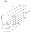
- a heating cable 10 is illustrated in cross section.
- Cable 10 has first and second electrical conductors 12 and 14, respectively, which are surrounded by an electrically insulating material 12a and 14a, respectively.
- a sheath 18 covers electrical conductors 12 and 14, and a jacket 20 covers sheath 18.
- Jacket 20 is illustrative of the heat transfer material of the present invention.
- Jacket 20 is a dielectric material, which is electrically non-conducting.
- conductors 12 and 14 may have a high voltage potential, yet jacket 20 allows heater cable 10 to be safely touched without electrical shock.
- Conductors 12 and 14 generate heat using electrical resistivity, and jacket 20 conducts that heat to a surface that is to be heated.
- jacket 20 serves as both the heat transfer material and the jacket, since jacket 20 is electrically non-conductive, but thermally conductive.
- the thermally conductive, electrically non-conductive jacket of the present invention approaches the conductivities of the prior art heat transfer materials. Additionally, the thermally conductive, electrically non-conductive jacket is flexible at temperature exposures up to and exceeding 450° F (232°C) and does not harden or adhere to the substrate.
- thermally conductive, electrically non-conductive jacket replaces the prior art heat transfer cement material and the silicone rubber jacket of the prior art rail heaters that was required in certain instances due to the electrically conductive prior art heat transfer materials using carbon fillers.
- Jacket material according to the present invention also replaces the prior art heat transfer cement material used without the silicone rubber jacket.
- the material of the present invention is an ideal solution for dissipating heat from a high wattage (10 to 70 W/ft (33 to 230 W/m)) rail heater. This material has a non-electrically conductive surface with a highly thermal conductive capability. Due to the retained flexibility of the jacket material, this material allows rail heaters to be reusable.
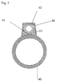
- a typical rail 30 is heated by a heater cable 32, which is made according to the present invention.
- Heater cable 10 of Fig. 1 would be suitable for use as heater cable 32 in Fig. 2.
- Clip 34 secures heater cable 32 to rail 30.
- Heater cable 32 has wires or conductors 32a and 32b and a jacket 32c, according to the present invention.
- heater cable 32 can have an expansion loop that extends away from the rail. Such expansion loops would be electrical-shock hazards, except heater cable 32 is covered with non-electrically conductive, but thermally conductive, heat transfer material 32c. Thus, a human or an animal can brush against the expansion loop without electrical shock.
- Heater cable 32 is covered with a thermally conductive material so that heat generated by its electrical conductors is readily transferred to rail 30.
- An electrical power source (not shown) is connected to heater cable 32 for providing electrical current for generating heat from heater cable 32.
- Heater cable 32 does not become hard or brittle, but instead remains flexible during service, even at temperatures as high as 450°F (232°C). Thus, a rail may be replaced, and heater cable 32 may be reused.
- the jacket material of the present invention is uniquely suitable for a wide range of applications.
- this new material can, in many instances, replace prior art materials (of the '458 patent) because the jacket material of the present invention has a high conductivity level and is removable and reusable.
- the present material does not tend to adhere to the heated surface as did the prior art material.
- a heat transfer material has been discovered that is electrically non-conductive, while also having advantageous properties including retained flexibility and tendency to not adhere to the heated surface during service.
- the present heat transfer material will enable self-regulating and power limiting heaters to reduce core temperatures and thus increase power output for a given resistivity level. Such heaters will allow constant wattage wire elements to be surrounded by the heat transfer material of the present invention, which serves as electrical insulation with a thermal conductance that allows an increase in the maximum current levels at which these heaters can safely operate.
- the heat transfer material of heating cables according to this invention has a substantially reduced electrical conductivity over prior art materials, with an electrical resistivity of 10 11 Ohms-cm or higher service.
- the heat transfer material is removable, reusable and stable to temperature levels in excess of 450° F (232°C). Even after extended operation, the heat transfer material does not cling to or adhere to the underlying heated substrate.
- Heating cables of this invention may be used as self-regulating, power limiting, and constant wattage electric heat tracing cables.
- Self-regulating cables have demonstrated increased power output by 7% or more with reduced operating core temperatures.
- the heat transfer material may be operated over the range of -60° F to 450° F (-51° C to 232° C) to form thermal bridges between heaters and the heated substrate.
- the heat transfer material has greatly improved burn resistance over prior art carbon loaded conductive materials.
- a TEK 3C40 BN cable sample (from Thermon Manufacturing Co. of San Marcos, Texas, U.S.A.) with a conductive silicone jacket according to the present invention was tested on an 85 lb (38.6Kg). composite rail.
- the purpose of this study was to investigate the heat transfer characteristic of the thermally conductive silicone jacketed cable and compare results with a regular (thermally non-conductive) silicone jacketed cable.
- the cable has an electrically conductive braid of copper wires and a jacket covering the wires, such as shown in Fig. 1.
- Fig. 3 shows that the jacket of the present invention is more thermally conductive than a silicone rubber that does not have fillers according to the present invention.
- thermally conductive silicone jacketed cable was tested on an 85 lb. (38.6Kg) composite rail.
- the heat transfer characters of thermally conductive silicone jacketed cable was compared to that of a regular silicone, SureFlow (SFOJ), jacketed cable.
- the temperature difference or delta T between the sheath and the jacket is lower for DT 40-600 BN thermally conductive silicone than for RDT 40-600 BNSFOJ when measured on the rail.
- the thermally conductive jacketed (RDT 40-600) cable runs much cooler (when it is away from the rail) than the cable sample jacketed with the SureFlow (SFOJ). TABLE 1. W/ft Vs.
- Volume resistivity for an insulating material is used to predict the dielectric breakdown of the materials. Volume resistivity was determined for conductive silicone of the present invention, silicone rubber, and graphite loaded heat transfer cement.
- Volume resistivity was measured on test samples per ASTM standard D257. A Model 1864 megOhm meter manufactured by General Radio was used for volume resistivity measurements on test samples. Terminal 1 was tied to the - unknown terminal, terminal 2 to the guard, and terminal 3 to the + unknown terminal. Volume resistance was measured at 500 volts for thermally conductive silicone and silicone rubber samples. Volume resistance for graphite loaded heat transfer cement was measured at 60 volts because volume resistance could not be measured at 500 volts as heat transfer cement was too conductive for this measurement at voltage above 70 volts.
- Volume resistivity was calculated from measured volume resistance in Ohms, the effective area of the measuring electrode in cm 2 , and average thickness of the specimen in cm. Table 3 summarizes the test results.
- the volume resistivity for the thermally conductive silicone is of the order of 10 12 Ohms-cm.
- the volume resistivity for the thermally conductive silicone is nearly equal to that measured for silicone rubber.
- the volume resistivity for thermally conductive silicone is 10 5 times greater than for graphite loaded heat transfer cement.
- the thermally conductive heat transfer material of the present invention exhibits essentially the same volume resistivity as regular, untreated silicone rubber, and it exhibits significantly greater volume resistivity than prior art heat transfer material, which is filled or loaded with graphite.
- the claimed material is electrically non-conductive, having an electrical resistivity of 10 11 Ohms-cm or higher.
- Sample No. Sample Description Sample Thickness (Cm) Electrode Area (Cm 2 ) Volume Resistivity (Ohm - Cm) 1 Thermally Conductive Silicone 0.30 50.26 10 12 4.33 x 10 12 2 Silicone Rubber 0.29 50.26 4.9 x 10 12 3 Graphite Loaded Heat Transfer Cement 0.21 50.26 2.8 x 10 7
- Jacket material on high power output cable may see a very high temperature when energized at high ambient temperature environment. Therefore, jacket material should be chosen such that it will not crack during high temperature exposure applications.
- This test compared RDT 40-600 BN conductive silicone jacket cable samples RDT 406-600 BNSFOJ cable samples, which are made from regular silicone rubber, which are made according to the present invention. Both cables are available from Therman Manufacturing Co. Two one foot (0.3m) long RDT 40-600 BN conductive silicone jacketed cable samples were exposed to 450°F (232°C) in an oven for a period of 14 days. Two control samples of RDT 40-600 BNSFOJ (SureFlow with regular silicone jacket) were tested side-by-side at 450°F (232°C) for 14 days. At the end of 14 days the oven temperature was brought to room temperature. Samples were removed from the oven and examined visually.
- thermally conductive silicone jacketed self-regulating cable samples were examined.
- Two foot (0.61m) long self-regulating (VSX 20-2) bare cable was tested in an environmental chamber at 50°F (10°C) ambient.
- Type J thermocouples were attached on the cable sample to measure sheath temperature.
- the cable was energized at 240 volts and a stable current was recorded after twenty minutes. Voltage and amperage were recorded with a Beckman 4410 meter and with an amp clamp. Thereafter, the same cable sample was jacketed with a thermally conductive silicone of the present invention, and power output and temperature measurements were performed in the environmental chamber at an ambient of temperature of 50°F (10°C).
- thermally conductive silicone was removed from the sample and a thermally non-conductive (regular) silicone was jacketed over the cable. Power output and sheath temperature were again measures at 50°F (10°C) in the chamber. Test results are summarized in Table 4. TABLE 4.
- the cable runs cooler by at least 8 °F (-13.3°C)with a thermally conductive silicone jacket as compared to the bare cable sample.
- Power output increased by 12% between the thermally conductive silicone jacketed cable versus the regular, thermally non-conductive, silicone jacketed cable sample.
- Thermally conductive silicone jacketed cable sample runs 20 °F (11°C) cooler than regular silicone jacketed cable sample.
- a heating cable comprising a thermally conductive, but electrically non-conductive, heat transfer material.
- the heat transfer material comprises a polymeric material, such as silicone rubber, and a nitride or oxide compound.
- the nitride or oxide is preferably selected from a group or compounds including aluminum nitride, boron nitride, silicon nitride, aluminum oxide and beryllium oxide.
- the nitride or oxide ranges preferably, but not absolutely necessarily, between about 30% and about 60% by volume.
- a plasticizer is preferably added in an amount of less than or equal to about 15% of the weight of the nitride or oxide for adding flexibility.
- the heat transfer material can be used in various articles including a jacket, covering or insulation layer for heating cables.
- One application is for rail heating, while others include electric heating and power cables.
- Cables according to the present invention are mechanically sturdy, while remaining flexible after use. Cables made with the present heat transfer material do not pose an electrical shock as the material has dielectric properties. Such articles do not become hard and brittle after use and do not adhere to the heated surface.
- the material and cables made therefrom have these desirable properties, as well as meeting thermal conductivity requirements.
- a heat transfer material having an electrical resistivity of 10 11 Ohms-cm or higher is used.
- Self-regulating, power limiting, constant wattage, and series resistance electric heat tracing cables as well as power conductors/cables are provided.
- the electrical insulation material has increased power output for self-regulating cable by approximately 7% or higher with reduced operating conductor/element temperatures.
Landscapes
- Chemical & Material Sciences (AREA)
- Health & Medical Sciences (AREA)
- Chemical Kinetics & Catalysis (AREA)
- Medicinal Chemistry (AREA)
- Polymers & Plastics (AREA)
- Organic Chemistry (AREA)
- Resistance Heating (AREA)
- Pipe Accessories (AREA)
- Compositions Of Macromolecular Compounds (AREA)
- Insulated Conductors (AREA)
- Lining Or Joining Of Plastics Or The Like (AREA)
- Laminated Bodies (AREA)
Abstract
Description
- The present invention relates to a heating cable comprising a generally to heat transfer material that is thermally conductive, but electrically non-conductive.
- The use of thermally conductive materials in heat tracing applications is known in the art. As early as 1954, filled thermally conductive materials were being commercially used in industrial heat tracing applications. Early heat transfer materials for heat tracing used carbon based fillers, such as graphite, loaded into a receiving base material such as sodium silicate, epoxy, etc. These materials were applied in paste form to the exterior of a tube through which steam was passed. The passage of steam through the tube caused the water in the sodium silicate to evaporate. This resulted in the heat transfer material hardening and thus permanently and physically bonding the steam tube to the process pipe to which it was mounted. This physical bonding enhanced the heat transfer between the steam tube and the process pipe and thus resulted in much higher maintenance temperatures on the process pipe than would be experienced by traditional steam tracing methods using no heat transfer material for a given steam/fluid temperature.
- In 1974, Bilbro et al. obtained U.S. Patent No. 3,834,458 for a new heat transfer material which achieved similar results as prior heat transfer materials but allowed for a partially cured conductive material to be snapped in place over the tube and then covered with a containing channel. The advantage here was the heat transfer material became molten and flowed to fill air gaps after steam was passed through the tube. The installation of the heat transfer material was cleaner and faster. The conductivities of the cured heat transfer material of the '458 patent were only slightly less than the previous paste-like heat transfer materials. The heat transfer material disclosed in the '458 patent was also extensively used with electric heat tracers by extruding the heat transfer material onto the electric cable at the factory and then shipping the electric heat tracer to the field on a reel. In the field, the electric cable with the extruded heat transfer cement was installed on a pipe and again covered with a channel.
- In recent years, certain applications have been identified where it is not possible to keep the extruded heat transfer cement material, as disclosed in the '458 patent, always beneath a channel. One specific application is the rail heating application. Specifically, when used with rail heating, the electric cable heater has to leave the rail at expansion joints and then after a one (0.3m) or two foot (0.61m) loop return to heat the rail. The prior art heating cable included an extruded thermally conductive and electrically conductive heat transfer material. The heat transfer material contained carbon black, which provides the required thermal conductivity, however, it is also highly electrically conductive.
- Since the prior art heat transfer material was electrically conductive, it posed a hazard for electrical shock. Thus, in the past, a thin silicone rubber jacket has been placed around the extruded heat transfer cement material to retain its shape at the excursion points of the heater cable from the rail. Since the rails in many cases were electrically alive (480 to 800 volts DC or AC potential), the silicone jacket material provided electrical insulation--should anyone brush against these loop arounds. Materials other than silicone have also been used for this purpose, one of which is described in U.S. Patent No. 4,391,425, issued to Keep.
- Many other applications also require dielectric jackets, so electrical conductivity of prior art heat transfer materials is often a problem. Due to the composition of the prior art heat transfer material used, the heat transfer material would cure and harden when placed into service. Consequently, prior art heating cable was typically not reusable after it was removed from a heated surface because it became hard and brittle during service. In the rail heating application, when rail replacement was necessary, it also became necessary to replace the heating cable.
- Similarly, heat transfer material that has been extruded onto a steam/fluid tracer tube and installed under a channel typically cannot be subsequently removed and reinstalled without damaging the heat transfer material. Most prior art heat transfer materials for steam/fluid tracing bond or adhere to some extent to the heated surface when in service, which again prevents reuse. Where heat transfer material has been used between two tubes, which have high expansion forces, the expansion forces have caused the material to crack.
- The document US-A-3 331 946 discloses a heating cable attached to a pipe comprising two heating conductors surrounded by a heat transfer material. This heating cable comprises a thermally conductive jacket that is not extruded around the electrical conductors.
- According to a first aspect of the present invention there is provided a heating cable, comprising a first electrical conductor, a second electrical conductor, and a thermally conductive jacket extruded around said electrical conductors:
- wherein said jacket comprises a thermally conductive, electrically non-conductive material comprising: a polymeric material and a nitride or oxide filler.
- According to a second aspect of the present invention there is provided a method of heating a substrate comprising the steps of:
- extruding a heating transfer material comprising a polymeric material, and (2) a nitride or oxide filler material over two electrical conductors thereby forming a flexible heating cable;
- providing a source of electrical power to the heating cable;
- allowing the electrical power source to generate an electrical current in the heating cable and thereby generate heat; and
- allowing the heat transfer material to transfer heat from the conductors to the substrate.
- A thermally conductive, but electrically non-conductive, heat transfer material is provided according to the present invention. For example, a jacket or insulation layer is provided for heating cables for rail heating applications, electric heating and power cables, jacketed steam/fluid tracer tubes, and removable/reusable thermal bridge strips for heat tracing tubes. The thermally conductive, but electrically non-conductive, articles so made are mechanically sturdy, but flexible. Cable, tubes, bridge strips and similar articles can be shipped on a reel to the final destination. A thermally conductive material for heat transfer devices is provided that retains flexibility after use, which has dielectric properties. Articles made with the present heat transfer material do not pose an electrical shock; do not become hard and brittle after use; and do not become bonded to the surface. Yet, the material meets thermal conductivity requirements.
- The thermally conductive, electrically non-conductive composition comprises a polymeric material, such as silicone rubber, and a nitride and/or oxide compound as a filler material. Suitable nitride and/or oxide compounds include, but are not limited to, aluminum nitride, boron nitride, silicon nitride, aluminum oxide and beryllium oxide. Compounds that are chemically or physically similar to the specified nitride and oxide compounds may be suitable as well. Preferably, additional plasticizer additives are included to increase the flexibility of the jacket material. The jacket material of the present invention has a thermal conductivity that approaches the thermal conductivities of prior art heat transfer materials, is not electrically conductive, and remains flexible at temperature exposures up to and exceeding 450° F (232°C) and does not harden or adhere to the substrate.
- A heating cable has a thermally conductive, electrically non-conductive jacket. Such a cable can be installed on a third rail that is usually electrically alive with 480 volts to 800 volts DC or AC potential. The heating cable with a jacket according to the present invention can be installed on a live third rail without a danger of electrical shock to the installer. The thermally conductive, electrically non-conductive jacket will not form a galvanic corrosion (cell) on the carbon steel third rail. The jacket can be extruded onto the cable during manufacture.
- A heating cable according to the present invention, with a thermally conductive, electrically non-conductive jacket, can be used in electric heat tracing applications, where reduced element and conductor operating temperatures are advantageous.
- It is desirable to have an improved thermally conductive, electrically non-conductive jacket for heating cable for rail heating applications. It is further desirable to have a thermally conductive jacket for a heat transfer element that retains flexibility after use. Many types of heating and power cable products require dielectric jackets. It would be advantageous for these heating cables to be jacketed with a highly thermally conductive material in order to reduce the inner conductor/element operating temperature. As these jackets are dielectric jackets, they should remain essentially electrically nonconductive. A heat transfer material according to the present invention or jacket, sheath, strip, insulator or covering made of it addresses these desires.
- The objects, advantages, and features of the invention will become more apparent by reference to the drawings which are appended hereto and wherein like numerals indicate like parts and wherein an illustrated embodiment of the invention is shown, in which:
- Fig. 1 is a sectional view of a heating cable having a thermally conductive, electrically non-conductive jacket, according to the present invention thereon;
- Fig. 2 shows the jacket material of the present invention used with a heating cable and mounted on a rail;
- Fig. 3 is a chart illustrating the performance of a heat transfer material according to the present invention.
- A thermally conductive, but electrically non-conductive, heat transfer material is useful as a jacket or insulation layer for a heating device. A jacket according to the present invention can be extruded onto a heating cable, which is a heating device that is particularly suitable for rail heating applications in addition to numerous other applications. The thermally conductive, but electrically non-conductive, cable so made is mechanically sturdy but flexible so that it can be shipped on a reel to the final destination.
- A thermally conductive, electrically non-conductive, heat transfer material of a heating cable according to the present invention is comprised of a polymeric material, such as a silicone rubber, and a filler material that adds thermal conductivity without adding electrical conductivity. The polymeric material is typically silicone rubber, but may be, for example, silicone gels, polyethylene, polypropylene, an elastomer, natural or synthetic rubber, or epoxy. Examples of the filler material include aluminum nitride (A1N), boron nitride (BN), silicon nitride (Si3N4), aluminum oxide (Al2O3), and beryllium oxide (BeO), but compounds or materials exhibiting similar chemical or physical properties may also be suitable. The filler is preferably provided in the range of approximately 30% to 60% by volume and more preferably in the range of 40% to 50% by volume.
- In order that the jacket of the present invention be flexible, additional plasticizer additives are included. The plasticizer additives are preferably, but not necessarily, silicone based modifiers such as Silastic HA-2 provided by Dow Coming (STI) Kendalhall, Indiana, U.S.A. The plasticizer loading is preferably in the range of approximately 0% to about 15% of filler weight and more preferably in the range of about 5% to about 10% of the filler weight.
- One heat transfer material according to this invention is a compounded mixture of silicone rubber and aluminum nitride (A1N) as the filler. The percent filler loading of aluminum nitride is preferably in the range of approximately 30% to 60% by volume and more preferably in the range of 40% to 50% by volume.
- The plasticizer loading is preferably in the range of approximately 0% to 15% of filler weight and more preferably in the range of 5% to 10% of the filler weight. Other property enhancers, such as fire retardants and ultra violet inhibitors, may also be used without substantially changing the material's heat transfer performance. Adhesive materials such as silicones and other similar materials can be used to bond, stick or adhere this compound to a substrate if desired.
- With reference to Fig. 1, a
heating cable 10 according to the present invention is illustrated in cross section.Cable 10 has first and secondelectrical conductors material sheath 18 coverselectrical conductors jacket 20 coverssheath 18.Jacket 20 is illustrative of the heat transfer material of the present invention.Jacket 20 is a dielectric material, which is electrically non-conducting. Thus,conductors jacket 20 allowsheater cable 10 to be safely touched without electrical shock. -
Conductors jacket 20 conducts that heat to a surface that is to be heated. In a prior art cable, an electrically non-conductive jacket or sheath would necessarily cover the heat transfer material to prevent electric shock.Jacket 20 serves as both the heat transfer material and the jacket, sincejacket 20 is electrically non-conductive, but thermally conductive. - The thermally conductive, electrically non-conductive jacket of the present invention approaches the conductivities of the prior art heat transfer materials. Additionally, the thermally conductive, electrically non-conductive jacket is flexible at temperature exposures up to and exceeding 450° F (232°C) and does not harden or adhere to the substrate.
- It is to be understood that the thermally conductive, electrically non-conductive jacket replaces the prior art heat transfer cement material and the silicone rubber jacket of the prior art rail heaters that was required in certain instances due to the electrically conductive prior art heat transfer materials using carbon fillers. Jacket material according to the present invention also replaces the prior art heat transfer cement material used without the silicone rubber jacket. As stated previously, the material of the present invention is an ideal solution for dissipating heat from a high wattage (10 to 70 W/ft (33 to 230 W/m)) rail heater. This material has a non-electrically conductive surface with a highly thermal conductive capability. Due to the retained flexibility of the jacket material, this material allows rail heaters to be reusable.
- With reference to Fig. 2, a
typical rail 30 is heated by aheater cable 32, which is made according to the present invention.Heater cable 10 of Fig. 1 would be suitable for use asheater cable 32 in Fig. 2.Clip 34 securesheater cable 32 to rail 30.Heater cable 32 has wires orconductors jacket 32c, according to the present invention. Whererail 30 joins another rail (not shown),heater cable 32 can have an expansion loop that extends away from the rail. Such expansion loops would be electrical-shock hazards, exceptheater cable 32 is covered with non-electrically conductive, but thermally conductive,heat transfer material 32c. Thus, a human or an animal can brush against the expansion loop without electrical shock. -
Heater cable 32 is covered with a thermally conductive material so that heat generated by its electrical conductors is readily transferred torail 30. An electrical power source (not shown) is connected toheater cable 32 for providing electrical current for generating heat fromheater cable 32.Heater cable 32 does not become hard or brittle, but instead remains flexible during service, even at temperatures as high as 450°F (232°C). Thus, a rail may be replaced, andheater cable 32 may be reused. - The jacket material of the present invention is uniquely suitable for a wide range of applications. For example, this new material can, in many instances, replace prior art materials (of the '458 patent) because the jacket material of the present invention has a high conductivity level and is removable and reusable. The present material does not tend to adhere to the heated surface as did the prior art material. Thus, a heat transfer material has been discovered that is electrically non-conductive, while also having advantageous properties including retained flexibility and tendency to not adhere to the heated surface during service.
- It is anticipated that the new level of flexibility and relatively high conductivity of the jacket material of the present invention will be useful in the construction of electric heat tracing cables. The present heat transfer material will enable self-regulating and power limiting heaters to reduce core temperatures and thus increase power output for a given resistivity level. Such heaters will allow constant wattage wire elements to be surrounded by the heat transfer material of the present invention, which serves as electrical insulation with a thermal conductance that allows an increase in the maximum current levels at which these heaters can safely operate.
- The heat transfer material of heating cables according to this invention has a substantially reduced electrical conductivity over prior art materials, with an electrical resistivity of 1011 Ohms-cm or higher service. The heat transfer material is removable, reusable and stable to temperature levels in excess of 450° F (232°C). Even after extended operation, the heat transfer material does not cling to or adhere to the underlying heated substrate.
- Heating cables of this invention may be used as self-regulating, power limiting, and constant wattage electric heat tracing cables. Self-regulating cables have demonstrated increased power output by 7% or more with reduced operating core temperatures. The heat transfer material may be operated over the range of -60° F to 450° F (-51° C to 232° C) to form thermal bridges between heaters and the heated substrate. The heat transfer material has greatly improved burn resistance over prior art carbon loaded conductive materials.
- A TEK 3C40 BN cable sample (from Thermon Manufacturing Co. of San Marcos, Texas, U.S.A.) with a conductive silicone jacket according to the present invention was tested on an 85 lb (38.6Kg). composite rail. The purpose of this study was to investigate the heat transfer characteristic of the thermally conductive silicone jacketed cable and compare results with a regular (thermally non-conductive) silicone jacketed cable. The cable has an electrically conductive braid of copper wires and a jacket covering the wires, such as shown in Fig. 1.
- An 8.83 foot (2.69m) long TEK 3C40 BN cable sample with thermally conductive silicone jacket was tested on a 8.66 foot (2.64m) long 85 lb. (38.6Kg) composite rail. A control cable sample (regular silicone jacket) of identical length was also tested. Cable samples were tested at 5, 10, 15, and 20 watts per foot (16.5, 33, 49.5, 66 watts/m) at ambient temperature of approximately 5 °F (-15°C). The rail assembly was tested in a cold chamber.
- Very significant temperature reductions (over standard silicone formulations) have been achieved with the new conductive silicone formulation as shown in Fig. 3. The lower the temperature difference between the braid and the exterior of the jacket, the more thermally conductive is the jacket because the jacket efficiently transfers heat from the braid. Fig. 3 shows that the jacket of the present invention is more thermally conductive than a silicone rubber that does not have fillers according to the present invention.
- A RDT 40-600 BN cable sample from Thermon Manufacturing Co. with a thermally conductive silicone jacket was tested on an 85 lb. (38.6Kg) composite rail. The heat transfer characters of thermally conductive silicone jacketed cable was compared to that of a regular silicone, SureFlow (SFOJ), jacketed cable.
- An 8.83 foot (2.69m) long RDT 40-600 BN cable sample with conductive silicone jacket was tested on a 8.66 foot (2.64m) long 85 lb. (38.6Kg) composite rail. A control cable sample (regular BNSF jacket) of identical length was also tested. J-type thermocouples were located on the cable, jacket, and rail. Cable samples were tested at 5, 10, 20, 30 and 40 watts per foot (16.5, 33, 66, 99 and 132 watts/m) at an ambient temperature of approximately -6°F (-21°C). The rail assembly was tested in a cold chamber. The sheath and jacket temperatures were also measured for cable away from the rail. Test results are summaries in Tables 1 and 2. The temperature difference or delta T between the sheath and the jacket is lower for DT 40-600 BN thermally conductive silicone than for RDT 40-600 BNSFOJ when measured on the rail. The thermally conductive jacketed (RDT 40-600) cable runs much cooler (when it is away from the rail) than the cable sample jacketed with the SureFlow (SFOJ).
TABLE 1. W/ft Vs. DeltaT for RDT 40-600 BNSFOJ Cable on Rail W/Ft (W/m) Average Braid Temperature for Cable on The Rail in °F (°C) Average Jacket Temperature for Cable on the Rail in °F (°C) T=Tbraid-Tjacket) °F (°C) 9.90 (32.67) 35.23 (1.66) 31.80 (-0.55) 2.57 (2.21) 20.25 (66.83) 78.90 (28.56) 72.42 (22.22) 6.47 (6.34) 30.41 (100.35) 121.22 (49.44) 111.85 (43.89) 9.37 (5.55) 40.82 (134.7) 162.65 (72.22) 148.27 (64.44) 14.37 (7.78) TABLE 2. W/ft Vs. Delta T for RDT 40-600 Conductive Silicone Jacketed Cable on Rail W/Ft (W/m) Average Braid Temperature for Cable on The Rail in °F (°C) Average Jacket Temperature for Cable on the Rail in °F (°C) T=Tbraid-Tjacket) °F (°C) 10.03 (33.10) 29.62 (-1.66) 27.02 (-2.78) 2.60 (1.12) 20.13 (66.43) 68.32 (20) 63.72 (17.22) 4.60 (2.78) 29.75 (98.18) 110.42 (43.33) 103.97 (39.44) 6.45 (3.89) 40.23 (132.76) 154.20 (67.78) 145.75 (62.78) 8.45 (5) - Volume resistivity for an insulating material is used to predict the dielectric breakdown of the materials. Volume resistivity was determined for conductive silicone of the present invention, silicone rubber, and graphite loaded heat transfer cement.
- Volume resistivity was measured on test samples per ASTM standard D257. A Model 1864 megOhm meter manufactured by General Radio was used for volume resistivity measurements on test samples. Terminal 1 was tied to the - unknown terminal, terminal 2 to the guard, and terminal 3 to the + unknown terminal. Volume resistance was measured at 500 volts for thermally conductive silicone and silicone rubber samples. Volume resistance for graphite loaded heat transfer cement was measured at 60 volts because volume resistance could not be measured at 500 volts as heat transfer cement was too conductive for this measurement at voltage above 70 volts.
- Volume resistivity was calculated from measured volume resistance in Ohms, the effective area of the measuring electrode in cm2, and average thickness of the specimen in cm. Table 3 summarizes the test results.
- The volume resistivity for the thermally conductive silicone is of the order of 1012 Ohms-cm. The volume resistivity for the thermally conductive silicone is nearly equal to that measured for silicone rubber. The volume resistivity for thermally conductive silicone is 105 times greater than for graphite loaded heat transfer cement.
- The thermally conductive heat transfer material of the present invention exhibits essentially the same volume resistivity as regular, untreated silicone rubber, and it exhibits significantly greater volume resistivity than prior art heat transfer material, which is filled or loaded with graphite. Thus, the claimed material is electrically non-conductive, having an electrical resistivity of 10 11 Ohms-cm or higher.
TABLE 3. Sample No. Sample Description Sample Thickness (Cm) Electrode Area (Cm2) Volume Resistivity (Ohm - Cm) 1 Thermally Conductive Silicone 0.30 50.26 1012 4.33 x 10¹² 2 Silicone Rubber 0.29 50.26 4.9 x 10¹² 3 Graphite Loaded Heat Transfer Cement 0.21 50.26 2.8 x 10⁷ - Jacket material on high power output cable may see a very high temperature when energized at high ambient temperature environment. Therefore, jacket material should be chosen such that it will not crack during high temperature exposure applications. This test compared RDT 40-600 BN conductive silicone jacket cable samples RDT 406-600 BNSFOJ cable samples, which are made from regular silicone rubber, which are made according to the present invention. Both cables are available from Therman Manufacturing Co. Two one foot (0.3m) long RDT 40-600 BN conductive silicone jacketed cable samples were exposed to 450°F (232°C) in an oven for a period of 14 days. Two control samples of RDT 40-600 BNSFOJ (SureFlow with regular silicone jacket) were tested side-by-side at 450°F (232°C) for 14 days. At the end of 14 days the oven temperature was brought to room temperature. Samples were removed from the oven and examined visually.
- Visual inspection indicated no damage or cracking on the RDT 40-600 BN conductive silicone jacketed cable samples. However, the control samples (RDT 40-600 BNSFOJ) samples had radial cracks all along the samples. Thus, RDT 40-600 BN conductive silicone jacketed cable will not crack when exposed to 450°F (232°C), but RDT 40-600 BNSFOJ will crack when exposed to 450°F (232°C). RDT 40-600 BN conductive silicone jacketed cable will retain flexibility even after exposure to 450°F (232°C), but RDT 40-600 BNSFOJ will lose flexibility when exposed to high temperatures. This test indicates that an article covered with the heat transfer material of the present invention will retain its flexibility after an extended period in service at temperatures as high as 450°F (232°C).
- This power output and temperature characteristics of thermally conductive silicone jacketed self-regulating cable samples were examined. Two foot (0.61m) long self-regulating (VSX 20-2) bare cable was tested in an environmental chamber at 50°F (10°C) ambient. Type J thermocouples were attached on the cable sample to measure sheath temperature. The cable was energized at 240 volts and a stable current was recorded after twenty minutes. Voltage and amperage were recorded with a Beckman 4410 meter and with an amp clamp. Thereafter, the same cable sample was jacketed with a thermally conductive silicone of the present invention, and power output and temperature measurements were performed in the environmental chamber at an ambient of temperature of 50°F (10°C). Finally, thermally conductive silicone was removed from the sample and a thermally non-conductive (regular) silicone was jacketed over the cable. Power output and sheath temperature were again measures at 50°F (10°C) in the chamber. Test results are summarized in Table 4.
TABLE 4. Cable Type And (Length) DC Resistance at 72°F (22,2°C) (Ohms) Measured Voltage (Volts) Stable Amperage (Amps) Power Output (W/Ft) (W/m) Sheath Temperature °F (°C) VSX 20-2 Bare (2 foot (61cm)) 520 238 0.183 21.8 (71.94) 149.0 (65) VSX 20-2 with 80 mil silicone conductive jacket (2 foot(61cm)) 530 239 0.195 23.3 (76.89) 140.8 (60) VSX 20-2 with regular non-conductive 80 mil Silicone jacket (2 foot (61cm)) 528 238 0.175 20.8 (68.64) 162 (72.22) - Power output increased by 7% from bare to thermally conductive silicone jacketed cable. The cable runs cooler by at least 8 °F (-13.3°C)with a thermally conductive silicone jacket as compared to the bare cable sample. Power output increased by 12% between the thermally conductive silicone jacketed cable versus the regular, thermally non-conductive, silicone jacketed cable sample. Thermally conductive silicone jacketed cable sample runs 20 °F (11°C) cooler than regular silicone jacketed cable sample. Thus, the power output and temperature characteristics of a jacket according to the present invention is better than that of either a bare, un-jacketed heater or a theater having a conventional silicone jacket.
- In summary, a heating cable comprising a thermally conductive, but electrically non-conductive, heat transfer material is provided. The heat transfer material comprises a polymeric material, such as silicone rubber, and a nitride or oxide compound. The nitride or oxide is preferably selected from a group or compounds including aluminum nitride, boron nitride, silicon nitride, aluminum oxide and beryllium oxide. The nitride or oxide ranges preferably, but not absolutely necessarily, between about 30% and about 60% by volume. A plasticizer is preferably added in an amount of less than or equal to about 15% of the weight of the nitride or oxide for adding flexibility.
- The heat transfer material can be used in various articles including a jacket, covering or insulation layer for heating cables. One application is for rail heating, while others include electric heating and power cables. Cables according to the present invention are mechanically sturdy, while remaining flexible after use. Cables made with the present heat transfer material do not pose an electrical shock as the material has dielectric properties. Such articles do not become hard and brittle after use and do not adhere to the heated surface. The material and cables made therefrom have these desirable properties, as well as meeting thermal conductivity requirements.
- A heat transfer material having an electrical resistivity of 1011 Ohms-cm or higher is used. Self-regulating, power limiting, constant wattage, and series resistance electric heat tracing cables as well as power conductors/cables are provided. The electrical insulation material has increased power output for self-regulating cable by approximately 7% or higher with reduced operating conductor/element temperatures.
- The foregoing disclosure and description of the invention are illustrative and explanatory thereof, and various changes in the details of the illustrated apparatus and construction and method of operation may be made without departing from the invention.
Claims (12)
- A heating cable, comprising a first electrical conductor (12;32a), a second electrical conductor (14;32b), and a thermally conductive jacket (20;32c)
that comprises a thermally conductive, electrically non-conductive material comprising: a polymeric material and a nitride or oxide filler characterized in that said jacket (20;32c) is extruded around said electrical conductors (12,14,32a,32b). - The cable of claim 1, further comprising a first electrical insulator (12a) surrounding said first electrical conductor (12), a second electrical insulator (14a) surrounding said second electrical conductor (14), and a sheath (18) covering both said first and second insulated electrical conductors (12,14), wherein said jacket (20) covers said sheath (18).
- The cable of claim 1 or claim 2, further comprising at least one clip (34) for securing the heating cable (32) to a railroad rail (30).
- The cable of any preceding claim, wherein the nitride or oxide filler material is selected from the group consisting of aluminum nitride, boron nitride, silicon nitride, aluminum oxide and beryllium oxide.
- The cable of claim 4, where in the filler material comprises aluminum nitride.
- The cable of any preceding claim, wherein the nitride or oxide filler material ranges between about 30% and about 60% by volume of the jacket composition.
- The cable of claim 6, wherein the filler material ranges between about 40 percent and 50 percent by volume of the jacket composition.
- The cable of any preceding claim, wherein said jacket (20) further comprises a plasticizer up to and including about 15% of the weight of the nitride or oxide filler material.
- The cable of any preceding claim, wherein the polymeric material is silicone rubber.
- The cable of any preceding claim, wherein the polymeric material and the filler material are present in amounts resulting in the jacket (20) having an electrical resistivity of about 1011 Ohms- cm or higher.
- The cable of claim 3 or any claim dependent thereon, wherein said heating cable (32) is removable and reusable.
- A method of heating a substrate comprising the steps of:extruding a heating transfer material comprising (1) a polymeric material, and (2) a nitride or oxide filler material over two electrical conductors thereby forming a flexible heating cable;providing a source of electrical power to the heating cable;allowing the electrical power source to generate an electrical current in the heating cable and thereby generate heat; andallowing the heat transfer material to transfer heat from the conductors to the substrate.
Applications Claiming Priority (3)
| Application Number | Priority Date | Filing Date | Title |
|---|---|---|---|
| US9294398P | 1998-07-15 | 1998-07-15 | |
| US92943P | 1998-07-15 | ||
| PCT/US1999/016196 WO2000004085A1 (en) | 1998-07-15 | 1999-07-15 | Thermally-conductive, electrically non-conductive heat transfer material and articles made thereof |
Publications (3)
| Publication Number | Publication Date |
|---|---|
| EP1123344A1 EP1123344A1 (en) | 2001-08-16 |
| EP1123344A4 EP1123344A4 (en) | 2002-10-23 |
| EP1123344B1 true EP1123344B1 (en) | 2006-06-21 |
Family
ID=22235896
Family Applications (1)
| Application Number | Title | Priority Date | Filing Date |
|---|---|---|---|
| EP99935657A Expired - Lifetime EP1123344B1 (en) | 1998-07-15 | 1999-07-15 | A heating cable |
Country Status (5)
| Country | Link |
|---|---|
| US (3) | US6410893B1 (en) |
| EP (1) | EP1123344B1 (en) |
| AU (1) | AU5109099A (en) |
| CA (1) | CA2337218C (en) |
| WO (1) | WO2000004085A1 (en) |
Cited By (1)
| Publication number | Priority date | Publication date | Assignee | Title |
|---|---|---|---|---|
| US10863588B2 (en) | 2015-02-09 | 2020-12-08 | Nvent Services Gmbh | Heater cable having a tapered profile |
Families Citing this family (39)
| Publication number | Priority date | Publication date | Assignee | Title |
|---|---|---|---|---|
| EP1123344B1 (en) * | 1998-07-15 | 2006-06-21 | Thermon Manufacturing Company | A heating cable |
| US6734398B1 (en) * | 2003-01-29 | 2004-05-11 | Michael D. Cecchi | Bladder system for controlling the temperature of laboratory fume hoods and working surfaces |
| US20050072334A1 (en) * | 2003-10-07 | 2005-04-07 | Saint-Gobain Performance Plastics, Inc. | Thermal interface material |
| US7568526B2 (en) * | 2004-07-29 | 2009-08-04 | Tyco Thermal Controls Llc | Subterranean electro-thermal heating system and method |
| US7322415B2 (en) * | 2004-07-29 | 2008-01-29 | Tyco Thermal Controls Llc | Subterranean electro-thermal heating system and method |
| KR100593628B1 (en) * | 2005-04-26 | 2006-07-03 | (주)에이오앤 | Heater jacket for heat convection |
| US8164031B2 (en) * | 2006-11-01 | 2012-04-24 | Parker-Hannifin Corporation | Electric trace tube bundle with internal branch circuit |
| US20080166552A1 (en) * | 2006-11-06 | 2008-07-10 | Arlon, Inc. | Silicone based compositions for thermal interface materials |
| US20080153959A1 (en) * | 2006-12-20 | 2008-06-26 | General Electric Company | Thermally Conducting and Electrically Insulating Moldable Compositions and Methods of Manufacture Thereof |
| US8418649B2 (en) * | 2007-12-19 | 2013-04-16 | Lam Research Corporation | Composite showerhead electrode assembly for a plasma processing apparatus |
| SG187387A1 (en) | 2007-12-19 | 2013-02-28 | Lam Res Corp | Film adhesive for semiconductor vacuum processing apparatus |
| US8910684B2 (en) * | 2008-07-03 | 2014-12-16 | Bridgestone Corporation | Tire innerliner with improved resistance to air permeability |
| US8735487B2 (en) * | 2008-07-03 | 2014-05-27 | Bridgestone Corporation | Tire components with improved heat transfer |
| BRPI0922270A2 (en) | 2008-12-06 | 2015-12-29 | 3Ip Pllc | improved heat transfer between tracer and tube |
| US8925543B2 (en) * | 2009-01-13 | 2015-01-06 | Aerojet Rocketdyne Of De, Inc. | Catalyzed hot gas heating system for pipes |
| US8157186B2 (en) * | 2009-01-23 | 2012-04-17 | Fastrax Industries, Inc. | Strike attachment railroad anchor |
| US8157185B2 (en) * | 2009-01-23 | 2012-04-17 | Fastrax Industries, Inc. | Strike attachment railroad signal line connector |
| KR101092407B1 (en) * | 2009-04-16 | 2011-12-09 | 박태환 | Radiating plate for cordless hair iron and cordless hair iron |
| CN101629402B (en) * | 2009-08-07 | 2010-12-01 | 孙健 | Fast snow melting device of railroad switch |
| US9138950B2 (en) * | 2011-08-30 | 2015-09-22 | Bridgestone Americas Tire Operations, Llc | Tire molding apparatus |
| US8813514B2 (en) * | 2012-08-06 | 2014-08-26 | Robert Hon-Sing Wong | Geothermal rail cooling and heating system |
| FR3017416B1 (en) * | 2014-02-12 | 2018-12-07 | Safran Aircraft Engines | COOLING A MAIN CHANNEL IN A FUEL SYSTEM WITH MULTIPOINT INJECTION |
| US10791871B2 (en) | 2014-03-17 | 2020-10-06 | Jong Peter Park | Travel mug for microwave oven |
| WO2016003815A1 (en) | 2014-06-30 | 2016-01-07 | AOI (Advanced Oilfield Innovations, Inc.) | Kerros or layered non-conductive ringed sealing pancake gasket assembly |
| CN106797682B (en) * | 2014-07-08 | 2020-08-07 | 朴钟道 | Container for microwave oven |
| WO2016025373A1 (en) * | 2014-08-12 | 2016-02-18 | Perma-Pipe, Inc. | Insulated and heat traced pipe assembly end sealing process |
| CN104462796A (en) * | 2014-11-24 | 2015-03-25 | 广州供电局有限公司 | Method and system for obtaining thermal resistance of three-core cable packing layer |
| US10123460B2 (en) | 2015-11-13 | 2018-11-06 | Covidien LLP | System and method for thermal management of electronic devices |
| WO2017120230A1 (en) | 2016-01-04 | 2017-07-13 | Pentair Thermal Management Llc | Anti-icing walkway with integrated control and switching |
| US10470251B2 (en) | 2016-04-29 | 2019-11-05 | Nvent Services Gmbh | Voltage-leveling monolithic self-regulating heater cable |
| WO2018142214A1 (en) | 2017-02-01 | 2018-08-09 | Pentair Flow Services Ag | Low smoke zero halogen self-regulating heating cable |
| US10870749B2 (en) | 2017-07-05 | 2020-12-22 | The University Of Akron | Thermally conductive polymers and methods for making |
| WO2019060402A1 (en) | 2017-09-21 | 2019-03-28 | Avx Corporation | Electrically insulating thermal connector having a low thermal resistivity |
| KR102029737B1 (en) * | 2017-10-27 | 2019-10-08 | 삼표레일웨이 주식회사 | Clip for thawing equipment of snow on railroad |
| US10533288B2 (en) * | 2018-01-30 | 2020-01-14 | Alstom Transport Technologies | Railroad track wire connection and corresponding railroad installation |
| WO2019173591A1 (en) * | 2018-03-07 | 2019-09-12 | The Regents Of The University Of Michigan | Thermoelectric thread for a heating and/or cooling device |
| EP3907423B1 (en) * | 2020-05-06 | 2022-07-20 | WWV Wärmeverwertung GmbH & Co. KG | Use of a flexible structure for transferring heat |
| US20220113095A1 (en) * | 2020-10-08 | 2022-04-14 | Controls Southeast, Inc. | Adjustable heat transfer element |
| CN116715960A (en) * | 2023-06-07 | 2023-09-08 | 昆山力普电子橡胶有限公司 | Mobile storage network hard disk protective sleeve and preparation method thereof |
Citations (2)
| Publication number | Priority date | Publication date | Assignee | Title |
|---|---|---|---|---|
| US3331946A (en) * | 1964-10-08 | 1967-07-18 | Thermon Mfg Co | Electric pipe heater |
| US3834458A (en) * | 1973-06-15 | 1974-09-10 | Thermon Mfg Co | Pipe heat transfer assembly and method of making same |
Family Cites Families (57)
| Publication number | Priority date | Publication date | Assignee | Title |
|---|---|---|---|---|
| US3900654A (en) * | 1971-07-15 | 1975-08-19 | Du Pont | Composite polymeric electric heating element |
| US3798415A (en) * | 1972-08-25 | 1974-03-19 | Graham Corp M | Electrically heated cooking utensil |
| US3800123A (en) * | 1973-01-19 | 1974-03-26 | M & M Enterprises Inc | Cooking and holding oven |
| CH582363A5 (en) * | 1974-07-12 | 1976-11-30 | Eltra Kg Leicht & Trambauer | |
| NL7511173A (en) * | 1975-09-23 | 1977-03-25 | Philips Nv | SELF-REGULATING HEATING ELEMENT. |
| USRE31081E (en) * | 1978-03-20 | 1982-11-16 | Railroad switch heater | |
| US4391425A (en) * | 1978-03-20 | 1983-07-05 | Keep Jr Henry | Railroad switch heater |
| JPS5541646A (en) * | 1978-09-18 | 1980-03-24 | Shinetsu Polymer Co | Hollow tubular heater |
| US4247756A (en) * | 1979-06-29 | 1981-01-27 | Victor Cucinotta | Heated floor mat |
| US4388523A (en) * | 1981-06-10 | 1983-06-14 | Multistress, Inc. | Electrical heating cable connector |
| US4429845A (en) * | 1982-04-26 | 1984-02-07 | Emerson Electric Co. | Rail track heaters |
| GB8310747D0 (en) * | 1983-04-20 | 1983-05-25 | Cooperheat | Heat tracing tape and controller |
| US4520260A (en) * | 1983-11-02 | 1985-05-28 | Eaton Corporation | Semi-conductive heating cable |
| JPS60112281A (en) * | 1983-11-18 | 1985-06-18 | 松下電工株式会社 | Heater |
| US4650972A (en) | 1985-10-04 | 1987-03-17 | Emerson Electric Co. | Heating cable and method of making same |
| US4870251A (en) * | 1985-11-01 | 1989-09-26 | Dennison Manufacturing Company | External heating of transfer pads |
| US5143649A (en) * | 1985-12-06 | 1992-09-01 | Sunbeam Corporation | PTC compositions containing low molecular weight polymer molecules for reduced annealing |
| US6415104B1 (en) * | 1987-05-14 | 2002-07-02 | World Properties, Inc. | Heating elements comprising polybutadiene and polyisoprene based thermosetting compositions |
| US5286952A (en) * | 1987-06-11 | 1994-02-15 | Raychem Corporation | Methods and devices which make use of conductive polymers to join articles |
| US5004190A (en) * | 1987-11-06 | 1991-04-02 | Bylin Heating Systems, Inc. | Rail heating apparatus |
| US4922083A (en) * | 1988-04-22 | 1990-05-01 | Thermon Manufacturing Company | Flexible, elongated positive temperature coefficient heating assembly and method |
| US5057673A (en) * | 1988-05-19 | 1991-10-15 | Fluorocarbon Company | Self-current-limiting devices and method of making same |
| US4957012A (en) * | 1989-06-16 | 1990-09-18 | The United States Of America As Represented By The Administrator Of The National Aeronautics And Space Administration | Predictive aging of polymers |
| US5113058A (en) * | 1990-06-01 | 1992-05-12 | Specialty Cable Corp. | PCT heater cable composition and method for making same |
| US5232970A (en) | 1990-08-31 | 1993-08-03 | The Dow Chemical Company | Ceramic-filled thermally-conductive-composites containing fusible semi-crystalline polyamide and/or polybenzocyclobutenes for use in microelectronic applications |
| ATE211296T1 (en) * | 1990-09-10 | 2002-01-15 | Tyco Electronics Corp | FLAME RETARDANT CONDUCTIVE POLYMER COMPOSITION DEVICE |
| JPH04272680A (en) * | 1990-09-20 | 1992-09-29 | Thermon Mfg Co | Switch-controlled-zone type heating cable and assembling method thereof |
| US5086836A (en) | 1990-11-02 | 1992-02-11 | Thermon Manufacturing Company | Retarding heat tracing system and method of making same |
| US6111234A (en) * | 1991-05-07 | 2000-08-29 | Batliwalla; Neville S. | Electrical device |
| US5194480A (en) | 1991-05-24 | 1993-03-16 | W. R. Grace & Co.-Conn. | Thermally conductive elastomer |
| US5250228A (en) * | 1991-11-06 | 1993-10-05 | Raychem Corporation | Conductive polymer composition |
| DE69328687D1 (en) | 1993-07-06 | 2000-06-21 | Toshiba Kawasaki Kk | HEAT-CONDUCTING PLATE |
| JP2698318B2 (en) * | 1993-08-20 | 1998-01-19 | ティーディーケイ株式会社 | heater |
| DE4338539A1 (en) * | 1993-11-11 | 1995-05-18 | Hoechst Ceram Tec Ag | Method of making ceramic heating elements |
| WO1995020819A1 (en) * | 1994-01-31 | 1995-08-03 | Nippon Tungsten Co., Ltd. | Flat ptc heater and resistance value regulating method for the same |
| JPH07280462A (en) * | 1994-04-11 | 1995-10-27 | Shin Etsu Chem Co Ltd | Soaking ceramic heater |
| JPH07295409A (en) * | 1994-04-25 | 1995-11-10 | Canon Inc | Heating/fixing device and manufacture thereof |
| CN1048109C (en) * | 1994-07-13 | 2000-01-05 | 松下电器产业株式会社 | Temp-sensing polymer body and tem-sensing element made therefrom |
| JPH08104812A (en) * | 1994-09-30 | 1996-04-23 | Toray Dow Corning Silicone Co Ltd | Silicone rubber composition |
| GB9602873D0 (en) * | 1996-02-13 | 1996-04-10 | Dow Corning Sa | Heating elements and process for manufacture thereof |
| US5681883A (en) * | 1996-03-05 | 1997-10-28 | Advanced Ceramics Corporation | Enhanced boron nitride composition and polymer based high thermal conductivity molding compound |
| US6005232A (en) * | 1996-06-28 | 1999-12-21 | Raychem Corporation | Heating cable |
| US5824997A (en) * | 1996-08-05 | 1998-10-20 | Fastrax Industries, Inc. | Railroad track switch heater |
| US5807507A (en) | 1996-08-28 | 1998-09-15 | Fuji Polymer Industries Co., Ltd. | Self-fusing conductive silicone rubber composition |
| US5786565A (en) * | 1997-01-27 | 1998-07-28 | Saint-Gobain/Norton Industrial Ceramics Corporation | Match head ceramic igniter and method of using same |
| EP1023370A1 (en) * | 1997-10-17 | 2000-08-02 | The Dow Chemical Company | Compositions of interpolymers of alpha-olefin monomers with one or more vinyl or vinylidene aromatic monomers |
| JP3477062B2 (en) * | 1997-12-26 | 2003-12-10 | 京セラ株式会社 | Wafer heating device |
| CA2322397A1 (en) * | 1998-03-11 | 1999-09-16 | Charles F. Diehl | Thermoplastic compositions of interpolymers of alpha-olefin monomers with one or more vinyl or vinylidene aromatic monomers and/or one or more hindered aliphatic or cycloaliphaticvinyl or vinylidene monomers blended with engineering thermoplastics |
| US5941482A (en) * | 1998-03-23 | 1999-08-24 | Thermal-Flex Systems, Inc. | Heating cable assembly and connector for railroad switch heating system |
| US6406817B2 (en) * | 1998-07-01 | 2002-06-18 | Ube Industries, Ltd. | Crosslinked polymer, electrolyte using the polymer, and nonaqueous secondary battery using the electrolyte |
| EP1123344B1 (en) * | 1998-07-15 | 2006-06-21 | Thermon Manufacturing Company | A heating cable |
| US6194692B1 (en) * | 1998-10-02 | 2001-02-27 | Engelhard Corporation | Electric heating sheet and method of making the same |
| US6415501B1 (en) * | 1999-10-13 | 2002-07-09 | John W. Schlesselman | Heating element containing sewn resistance material |
| US6288372B1 (en) * | 1999-11-03 | 2001-09-11 | Tyco Electronics Corporation | Electric cable having braidless polymeric ground plane providing fault detection |
| US6433317B1 (en) * | 2000-04-07 | 2002-08-13 | Watlow Polymer Technologies | Molded assembly with heating element captured therein |
| US6392206B1 (en) * | 2000-04-07 | 2002-05-21 | Waltow Polymer Technologies | Modular heat exchanger |
| ATE350881T1 (en) * | 2000-10-19 | 2007-01-15 | Heat Trace Ltd | HEATING CABLE |
-
1999
- 1999-07-15 EP EP99935657A patent/EP1123344B1/en not_active Expired - Lifetime
- 1999-07-15 CA CA002337218A patent/CA2337218C/en not_active Expired - Fee Related
- 1999-07-15 WO PCT/US1999/016196 patent/WO2000004085A1/en active IP Right Grant
- 1999-07-15 AU AU51090/99A patent/AU5109099A/en not_active Abandoned
- 1999-07-15 US US09/353,675 patent/US6410893B1/en not_active Expired - Fee Related
-
2002
- 2002-06-07 US US10/165,441 patent/US6762395B2/en not_active Expired - Fee Related
-
2004
- 2004-07-09 US US10/887,941 patent/US7321107B2/en not_active Expired - Fee Related
Patent Citations (2)
| Publication number | Priority date | Publication date | Assignee | Title |
|---|---|---|---|---|
| US3331946A (en) * | 1964-10-08 | 1967-07-18 | Thermon Mfg Co | Electric pipe heater |
| US3834458A (en) * | 1973-06-15 | 1974-09-10 | Thermon Mfg Co | Pipe heat transfer assembly and method of making same |
Cited By (1)
| Publication number | Priority date | Publication date | Assignee | Title |
|---|---|---|---|---|
| US10863588B2 (en) | 2015-02-09 | 2020-12-08 | Nvent Services Gmbh | Heater cable having a tapered profile |
Also Published As
| Publication number | Publication date |
|---|---|
| US7321107B2 (en) | 2008-01-22 |
| AU5109099A (en) | 2000-02-07 |
| EP1123344A4 (en) | 2002-10-23 |
| WO2000004085A9 (en) | 2000-07-20 |
| CA2337218C (en) | 2009-04-28 |
| US6410893B1 (en) | 2002-06-25 |
| US20050067403A1 (en) | 2005-03-31 |
| CA2337218A1 (en) | 2000-01-27 |
| WO2000004085A1 (en) | 2000-01-27 |
| EP1123344A1 (en) | 2001-08-16 |
| US6762395B2 (en) | 2004-07-13 |
| US20030034344A1 (en) | 2003-02-20 |
Similar Documents
| Publication | Publication Date | Title |
|---|---|---|
| EP1123344B1 (en) | A heating cable | |
| US7476702B2 (en) | Polymer electronic device package having high thermal conductivity and dielectric strength | |
| US10373738B2 (en) | Insulated wire construction with liner | |
| TWI507461B (en) | Polymeric compositions with voltage stabilizer additive | |
| GB2095024A (en) | Insulated high voltage cables | |
| KR20130114114A (en) | Coated conductor with voltage stabilized inner layer | |
| JPS583322B2 (en) | Method for improving the electrical insulation properties of the outer surface of solid electrical insulators | |
| US11031766B2 (en) | Cable accessory with improved thermal conductivity | |
| Mauseth et al. | Diagnostic testing of thermally aged medium voltage XLPE cable joints | |
| KR20170012003A (en) | Method for evaluating water resistance in cable | |
| JP5473926B2 (en) | Reduction of dielectric loss through the use of organoclays in semiconductor or insulator compositions. | |
| Koo et al. | Comparison of DC and AC surface breakdown characteristics of GFRP and epoxy nanocomposites in liquid nitrogen | |
| Yaacob et al. | Dielectric properties of polyvinyl chloride with wollastonite filler for the application of high-voltage outdoor insulation material | |
| Katz et al. | Emergency Overioad Characteristics Of Extruded Dielectric Cables Operating At 1300 And Above | |
| Afifi et al. | Electrical Tracking and Erosion of Silicone Rubber Filled with Alumina Tri-Hydrate | |
| JPS587204B2 (en) | Modification method of insulation compound | |
| Santulli et al. | Thermomechanical and electrical characterisation of EVA polymer compounds for cable accessories | |
| JPH11140321A (en) | Silicone rubber composition for power cable coating | |
| AU568802B2 (en) | Flame retardant wire with high insulation resistance | |
| Kotte et al. | Influence of the cure parameters on the partial discharge behavior of cast resins | |
| Miyashita et al. | New approach to elucidate the properties of carbon black-filled semiconducting materials for high voltage power cables | |
| Chang et al. | Thermally stimulated discharge current and DC resistivity of ethylene propylene rubberwith various Pb concentrations | |
| JPH08289454A (en) | Rubber mold stress cone | |
| Kultzow | High thermally conductive epoxy system for electrical and electronic thermal management | |
| Rashid et al. | Tracking Investigation of High Temperature Vulcanized Silicone rubber with Hybrid Nano/Micro Silica Composite Insulators |
Legal Events
| Date | Code | Title | Description |
|---|---|---|---|
| PUAI | Public reference made under article 153(3) epc to a published international application that has entered the european phase |
Free format text: ORIGINAL CODE: 0009012 |
|
| 17P | Request for examination filed |
Effective date: 20010215 |
|
| AK | Designated contracting states |
Kind code of ref document: A1 Designated state(s): AT BE CH CY DE DK ES FI FR GB GR IE IT LI LU MC NL PT SE |
|
| AX | Request for extension of the european patent |
Free format text: AL;LT;LV;MK;RO;SI |
|
| A4 | Supplementary search report drawn up and despatched |
Effective date: 20020905 |
|
| AK | Designated contracting states |
Kind code of ref document: A4 Designated state(s): AT BE CH CY DE DK ES FI FR GB GR IE IT LI LU MC NL PT SE |
|
| RIC1 | Information provided on ipc code assigned before grant |
Free format text: 7H 05B 3/56 A, 7E 01B 5/00 B |
|
| 17Q | First examination report despatched |
Effective date: 20040115 |
|
| GRAP | Despatch of communication of intention to grant a patent |
Free format text: ORIGINAL CODE: EPIDOSNIGR1 |
|
| RTI1 | Title (correction) |
Free format text: A HEATING CABLE |
|
| DAX | Request for extension of the european patent (deleted) | ||
| RBV | Designated contracting states (corrected) |
Designated state(s): GB SE |
|
| REG | Reference to a national code |
Ref country code: DE Ref legal event code: 8566 |
|
| GRAS | Grant fee paid |
Free format text: ORIGINAL CODE: EPIDOSNIGR3 |
|
| GRAA | (expected) grant |
Free format text: ORIGINAL CODE: 0009210 |
|
| AK | Designated contracting states |
Kind code of ref document: B1 Designated state(s): GB SE |
|
| REG | Reference to a national code |
Ref country code: GB Ref legal event code: FG4D |
|
| PG25 | Lapsed in a contracting state [announced via postgrant information from national office to epo] |
Ref country code: SE Free format text: LAPSE BECAUSE OF FAILURE TO SUBMIT A TRANSLATION OF THE DESCRIPTION OR TO PAY THE FEE WITHIN THE PRESCRIBED TIME-LIMIT Effective date: 20060921 |
|
| PLBE | No opposition filed within time limit |
Free format text: ORIGINAL CODE: 0009261 |
|
| STAA | Information on the status of an ep patent application or granted ep patent |
Free format text: STATUS: NO OPPOSITION FILED WITHIN TIME LIMIT |
|
| GBPC | Gb: european patent ceased through non-payment of renewal fee |
Effective date: 20060921 |
|
| 26N | No opposition filed |
Effective date: 20070322 |
|
| PG25 | Lapsed in a contracting state [announced via postgrant information from national office to epo] |
Ref country code: GB Free format text: LAPSE BECAUSE OF NON-PAYMENT OF DUE FEES Effective date: 20060921 |