EP1122891A1 - Funkempfänger und Verfahren zu dessen Verwendung - Google Patents
Funkempfänger und Verfahren zu dessen Verwendung Download PDFInfo
- Publication number
- EP1122891A1 EP1122891A1 EP00850018A EP00850018A EP1122891A1 EP 1122891 A1 EP1122891 A1 EP 1122891A1 EP 00850018 A EP00850018 A EP 00850018A EP 00850018 A EP00850018 A EP 00850018A EP 1122891 A1 EP1122891 A1 EP 1122891A1
- Authority
- EP
- European Patent Office
- Prior art keywords
- signal
- filter
- filters
- different
- filtered
- Prior art date
- Legal status (The legal status is an assumption and is not a legal conclusion. Google has not performed a legal analysis and makes no representation as to the accuracy of the status listed.)
- Withdrawn
Links
Images

Classifications
-
- H—ELECTRICITY
- H04—ELECTRIC COMMUNICATION TECHNIQUE
- H04L—TRANSMISSION OF DIGITAL INFORMATION, e.g. TELEGRAPHIC COMMUNICATION
- H04L25/00—Baseband systems
- H04L25/02—Details ; arrangements for supplying electrical power along data transmission lines
- H04L25/0202—Channel estimation
-
- H—ELECTRICITY
- H04—ELECTRIC COMMUNICATION TECHNIQUE
- H04B—TRANSMISSION
- H04B7/00—Radio transmission systems, i.e. using radiation field
- H04B7/005—Control of transmission; Equalising
-
- H—ELECTRICITY
- H04—ELECTRIC COMMUNICATION TECHNIQUE
- H04L—TRANSMISSION OF DIGITAL INFORMATION, e.g. TELEGRAPHIC COMMUNICATION
- H04L1/00—Arrangements for detecting or preventing errors in the information received
- H04L1/20—Arrangements for detecting or preventing errors in the information received using signal quality detector
Definitions
- the invention is concerned with a radio receiver for discrimination of a desired signal from a received signal by filtering.
- the invention is also concerned with a method in such a radio receiver.
- the information is sent by frequency, amplitude or phase modulating of a radio wave with a processed information signal.
- the received radio signal containing the information is then demodulated in a receiver to recreate the original information signal.
- the functional components in a digital receiver contains e.g. an antenna through which the signal is received, frequency units to convert the radio frequency to a frequency suitable for processing, an analogue/digital A/D converter to digitize the received analogue signal by sampling and a demodulator to demodulate the signal and recreate the original information signal.
- ISI Inter Symbol Interference
- the digital information signal to be demodulated contains a sequence of symbols in a given order. These symbols may correspond to bits. A training sequence with known symbols can be used to estimate the channel.
- h(n) can be estimated, for example when a training sequence, wherein d(n) is known, is used.
- An example of a channel estimation method is the Least Square Method (LSM).
- LSM Least Square Method
- the desired signal can then be derived from the received signal using algorithms for obtaining an estimate for the desired information signal. Examples of such algorithms are the MLSE algorithm and the RAKE receiver.
- a receiver filter is applied in the receivers before demodulation, for filtering out as much as possible of the unwanted parts and not introduce too much ISI.
- a receiver filter can be analogue or digital depending on where it is positioned, i.e. in the analogue domain before the A/D converter or the digital domain after the A/D converter.
- the receiver filter is a combination of several filters, analog or digital.
- the filter will have several effects on the received signal in more or less extent, for example to reduce the amount of noise that enters the receiver, colour of the noise, affect the amount of Inter Symbol Interference (ISI), suppress adjacent interferers, etc.
- ISI Inter Symbol Interference
- the optimum filter depends on the spectrum of the wanted signal, the interference situation (noise, co-channel interference, and/or adjacent interference) and the channel. Furthermore, the demodulator's ability to handle ISI will influence the choice of receiver filter.
- a narrow filter will reduce noise more than a wider filter, colour noise heavily, introduce much ISI, suppress adjacent interferers well, etc., while a wider filter will not reduce noise as much as a narrower filter, but colours noise less, introduces less ISI, and is less efficient at suppressing adjacent interferes.
- a single filter is always a compromise between several aspects, and it would be desirable to benefit from different filters.
- the object of the invention is therefore to develop a method with which the best filter can be chosen in every situation and which does not have the disadvantages of said prior art methods.
- the method of the invention for deriving a desired signal from a received signal, comprising the desired signal and unwanted signals, is performed by filtering away the unwanted signals from the received signal.
- a signal is received as a combination of the desired signal and unwanted signals.
- the received signal is then filtered in parallell through the different filters.
- the channel is individually estimated for each filtered parallell signal. The signal that is estimated to give the best performance is chosen after which it is demodulated.
- the different filters used are filters in a filter bank, wherein the filters can advantageously range from very wide (e.g. a Nyquist filter) to very narrow.
- the synchronization and the channel estimation may for instance be performed using the training sequences in e.g. GSM (Global System of Mobile Communication) and EDGE (Enhanced Data Rates for Global Evolution).
- GSM Global System of Mobile Communication
- EDGE Enhanced Data Rates for Global Evolution
- a channel estimation metric e.g. estimated residual noise power or estimated Signal Noise Ratio (SNR)
- SNR Signal Noise Ratio
- the demodulator may comprise an equalizer, rake receiver or similar elements known in themselves. It may also contain other functions, such as whitening filters, IRC (Interference Radio Combining) algorithms, prefilters etc.
- IRC Interference Radio Combining
- the basic idea of the invention is to do parallell filterings, with receiver filters with different properties, and use the one which is estimated to give the best performance.
- the choice is based on individual channel estimations, where the branch giving the best channel estimation metric is chosen.
- the selection procedure can be used for each burst (or slot) individually, or averaging can be utilized.
- the decision process includes an averaging process or low-pass filtering of the quality metrics for each branch filtering of functions of the quality metrics.
- the proposed method improves the performance in different environments and situations.
- two different filters are used (narrow and wide).
- the gain is in the order of 2dB in the co-channel case or 4dB in the adjacent channel case, depending on what is the reference case.
- the channel is low dispersive (TU (Typical Urban) model,) and the gain is expected to be significantly larger in more dispersive cases (e.g. HT (Hilly Terrain) model).
- the implementation requirements can be reduced, i.e. the implementation of the individual filters can be less accurate.
- FIG. 1 is a general illustration of the invention.
- a signal which is a combination of the desired signal and noise and interference, is received through an antenna 1.
- the received signal is then filtered in parallell through the different filters in a filter bank 2.
- Each branch uses individual channel estimations C1....CN for the filtered signals.
- the signal that is estimated to give the best performance is chosen 3 by means of a control signal 5 after which is demodulated 4 to recreate the original information signal.
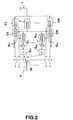
- FIG 2 An example of how the channel estimation metrics can be obtained is given in figure 2, where the channel is estimated using a training sequence.
- a signal which is a combination of the desired signal and noise and interference, is received through an antenna 1.
- the received signal is then filtered in parallell through the different filters F1...FN in a filter bank.
- the radio channel is individually estimated C1....CN for each filtered signal.
- the best filter is chosen 10, and the corresponding signal is demodulated 4 and processed further to recreate the original information signal.
- the metric is the residual noise and is calculated by filtering 6 C1 , 6 CN the known training sequence 7 through each channel estimate, and thereby obtaining an estimate for each received sample that corresponds to the training sequence.
- the residual noise power can be calculated mathematically by comparing the estimated samples and the received samples e.g. by forming the normalized squared sum 8 C1 - 8 CN of the differences 9 C1 - 9 CN formed by subtracting the actual samples from the estimated samples. This can also be expressed as
- ⁇ could depend on the number of training symbols and the number of channel taps
- ⁇ is the residual noise power
- y(n) are the received samples
- ( n ) are the estimated samples
- ( k ) are the estimated channel taps
- d(k) are the known training symbols
- N is the number of training symbols
- L is the channel memory (and L + 1 is the number of channel taps).
- LS Least Square
- Another example would be to estimate the SNR for each branch as channel estimation metric and choose the one with the highest estimated SNR, which approximately is
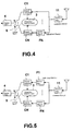
- a first embodiment of the invention is presented in figure 3.
- a signal which is a combination of the desired signal and noise and interference, is received through an antenna 1.
- the received signal is then filtered in parallell through the different filters F1...FN in a filter bank.
- Each channel is individually estimated C1....CN for the filtered signals.
- the signal that is estimated to give the best performance is chosen 3 after which it is demodulated 4 to recreate the original information signal.
- the receiver filters may be analogue or digital. They can also comprise several analogue and/or digital filters in series depending on implementation.
- the Receiver Filters F1 - FN for different branches may be constructed in different ways, according to the former sentence. However, the last analogue filter for a branch will also contain a sampling process as the channel estimation takes place in the digital domain.
- the digital signal may be downsampled in conjunction with some of the filterings.
- the downsampling may be different for the different filter components for a branch (if there are several filters in series).
- the downsampling process may also be done differently for different branches.
- the channel estimation may be fractionally spaced and then downsampled, i.e. the channel estimation can be improved by means of several samples per symbol. It may also be fractionally spaced without a succeeding downsampling.
- the demodulator may be fractionally spaced, if the signal from the chosen branch is oversampled.
- the received signal can first be filtered with a wide filter 5 (for instance a Nyqvist filter).
- This common filter may actually be constructed as a combination of different filters with different properties, but is however represented by a single filter in this description.
- a bank of filters 2 is used parallelly on the signal and in an embodiment shown in figure 4, there is not used any extra filter in one branch, i.e. only the first filter is used, and in that branch the channel estimation is done directly after the first common filter. Individual channel estimations providing a quality metric for each branch, followed by a selection process is then used as described above in connection with figure 3.
- the components may vary with regard to if they are analogue/digital, oversampled/symbolsampled and symbol spaced/fractionally spaced.
- One advantage with this embodiment is that it is possible to put all analogue filters in the common filter part, and let digital filter characteristics per individual branch. This does not exclude having digital filters in the common part.
- Another advantage is that, if the common filter has the necessary characteristic, the sampling rate for the individual branches may be reduced.
- the individual branch step filters in figure 3 compared to figures 4 and 5 could be chosen as the "delta filters” between the first wide filter and more narrow filters in the first embodiment.
- the individual branch step filters in figures 4 and 5 could be chosen as "delta filters” so that they together with the first wide filter act as the filters in the first embodiment. If the filters are chosen in this way, the two embodiments will act very similarly, if not even exactly the same.
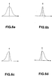
- the filter bank could for instance contain one wide filter (for use without adjacent interferers), one narrow filter (for use with many adjacent interferers), one asymmetrical filter which is wide for lower frequencies and narrow for higher frequencies (for use with strong adjacent interferers on one carrier spacing up in frequency) and one asymmetrical filter, which is wide for higher frequencies and narrow for lower frequencies (for use with strong adjacent interferers on one carrier spacing below in frequency.
- the X-axis represents the frequency and the Y-axis power.
- Figure 6a shows the spectrum of a wide filter, which is suitable when there is no strong adjacent channel interference.
- Figure 6b shows the spectrum of a narrow filter, which is suitable when there are strong adjacent channel interference on both sides.
- Figure 6c shows the spectrum of an example of an asymmetric filter, which is suitable when there are strong adjacent channel interference on the right side.
- Figure 6d shows the spectrum of an example of an asymmetric filter, which is suitable when there are strong adjacent channel interference on the left side.
Priority Applications (1)
| Application Number | Priority Date | Filing Date | Title |
|---|---|---|---|
| EP00850018A EP1122891A1 (de) | 2000-01-31 | 2000-01-31 | Funkempfänger und Verfahren zu dessen Verwendung |
Applications Claiming Priority (1)
| Application Number | Priority Date | Filing Date | Title |
|---|---|---|---|
| EP00850018A EP1122891A1 (de) | 2000-01-31 | 2000-01-31 | Funkempfänger und Verfahren zu dessen Verwendung |
Publications (1)
| Publication Number | Publication Date |
|---|---|
| EP1122891A1 true EP1122891A1 (de) | 2001-08-08 |
Family
ID=8175637
Family Applications (1)
| Application Number | Title | Priority Date | Filing Date |
|---|---|---|---|
| EP00850018A Withdrawn EP1122891A1 (de) | 2000-01-31 | 2000-01-31 | Funkempfänger und Verfahren zu dessen Verwendung |
Country Status (1)
| Country | Link |
|---|---|
| EP (1) | EP1122891A1 (de) |
Cited By (4)
| Publication number | Priority date | Publication date | Assignee | Title |
|---|---|---|---|---|
| WO2004057766A2 (en) | 2002-12-19 | 2004-07-08 | Texas Instruments Sunnyvale Incorporated | Wireless receiver and method for determining a representation of noise level of a signal |
| WO2006027603A1 (en) * | 2004-09-10 | 2006-03-16 | Ttpcom Limited | Method and apparatus for selecting a channel filter for a communication system |
| WO2007021952A2 (en) * | 2005-08-12 | 2007-02-22 | Qualcomm Incorporated | Channel estimation for wireless communication |
| US20240064044A1 (en) * | 2022-08-19 | 2024-02-22 | Nvidia Corporation | Signal processing in parallel |
Citations (3)
| Publication number | Priority date | Publication date | Assignee | Title |
|---|---|---|---|---|
| US5465410A (en) * | 1994-11-22 | 1995-11-07 | Motorola, Inc. | Method and apparatus for automatic frequency and bandwidth control |
| EP0715417A2 (de) * | 1994-11-28 | 1996-06-05 | Nec Corporation | Mobilfunktelefon mit Verfahren und Schaltung zum adaptiven Einsatz von ZF-Filtern |
| US5715282A (en) * | 1996-05-08 | 1998-02-03 | Motorola, Inc. | Method and apparatus for detecting interference in a receiver for use in a wireless communication system |
-
2000
- 2000-01-31 EP EP00850018A patent/EP1122891A1/de not_active Withdrawn
Patent Citations (3)
| Publication number | Priority date | Publication date | Assignee | Title |
|---|---|---|---|---|
| US5465410A (en) * | 1994-11-22 | 1995-11-07 | Motorola, Inc. | Method and apparatus for automatic frequency and bandwidth control |
| EP0715417A2 (de) * | 1994-11-28 | 1996-06-05 | Nec Corporation | Mobilfunktelefon mit Verfahren und Schaltung zum adaptiven Einsatz von ZF-Filtern |
| US5715282A (en) * | 1996-05-08 | 1998-02-03 | Motorola, Inc. | Method and apparatus for detecting interference in a receiver for use in a wireless communication system |
Cited By (14)
| Publication number | Priority date | Publication date | Assignee | Title |
|---|---|---|---|---|
| EP1584141A2 (de) * | 2002-12-19 | 2005-10-12 | Texas Instruments Sunnyvale Incorporated | Drahtloser empfänger und verfahren zur bestimmung einer repräsentation des rauschpegels eines signals |
| WO2004057766A2 (en) | 2002-12-19 | 2004-07-08 | Texas Instruments Sunnyvale Incorporated | Wireless receiver and method for determining a representation of noise level of a signal |
| EP1584141A4 (de) * | 2002-12-19 | 2011-07-27 | Texas Instr Sunnyvale Inc | Drahtloser empfänger und verfahren zur bestimmung einer repräsentation des rauschpegels eines signals |
| CN101015127B (zh) * | 2004-09-10 | 2010-09-29 | 开曼晨星半导体公司 | 供通信系统选择信道滤波器的方法及装置 |
| WO2006027603A1 (en) * | 2004-09-10 | 2006-03-16 | Ttpcom Limited | Method and apparatus for selecting a channel filter for a communication system |
| US8743910B2 (en) | 2004-09-10 | 2014-06-03 | Mstar Semiconductor, Inc. | Method and apparatus for selecting a channel filter for a communication system |
| WO2007021952A2 (en) * | 2005-08-12 | 2007-02-22 | Qualcomm Incorporated | Channel estimation for wireless communication |
| EP2226949A1 (de) * | 2005-08-12 | 2010-09-08 | Qualcomm Incorporated | Kanalschätzung für drahtlose Kommunikation |
| US8165186B2 (en) | 2005-08-12 | 2012-04-24 | Qualcomm Incorporated | Channel estimation for wireless communication |
| US8437380B2 (en) | 2005-08-12 | 2013-05-07 | Qualcomm Incorporated | Channel estimation for wireless communication |
| US8625656B2 (en) | 2005-08-12 | 2014-01-07 | Qualcomm Incorporated | Channel estimation for wireless communication |
| WO2007021952A3 (en) * | 2005-08-12 | 2007-04-12 | Qualcomm Inc | Channel estimation for wireless communication |
| CN101283559B (zh) * | 2005-08-12 | 2015-02-18 | 高通股份有限公司 | 在无线通信系统中导出信道估计值的设备和方法 |
| US20240064044A1 (en) * | 2022-08-19 | 2024-02-22 | Nvidia Corporation | Signal processing in parallel |
Similar Documents
| Publication | Publication Date | Title |
|---|---|---|
| KR970007362B1 (ko) | 수신기에서의 손상된 신호 등화 장치 및 방법 | |
| US7031411B2 (en) | Methods and apparatus for canceling co-channel interference in a receiving system using spatio-temporal whitening | |
| US7187736B2 (en) | Reducing interference in a GSM communication system | |
| US6944245B2 (en) | Multi-pass interference reduction in a GSM communication system | |
| EP1639719B1 (de) | Verfahren und Vorrichtung zur Unterdrückung von Co-Kanalstörungen in einem Empfänger | |
| EP0453213B1 (de) | Reduzierung von Interferenzen in RF-Signalen | |
| CN109889218B (zh) | 一种单通道同频干扰识别与抵消方法 | |
| JP4778007B2 (ja) | 入力ノイズ白色化フィルタの適応動作によって受信信号をフィルタする装置および関連方法 | |
| WO2005107084A2 (en) | Method and apparatus for improving mlse in the presence of co-channel interferer for gsm/gprs systems | |
| WO2005109808A1 (en) | Detection of modulation type | |
| CA2143074C (en) | A .pi./4-dqpsk delay spread detection and compensation apparatus and method | |
| KR101828790B1 (ko) | 주파수 편이 변조 신호의 수신 방법 및 장치 | |
| US7864879B2 (en) | System having a signal processor for detection of a signal type | |
| US7039093B2 (en) | Arrangement for adaptive baseband filter selection | |
| KR101075117B1 (ko) | 통신 시스템에서의 채널 필터를 선택하는 방법 및 장치 | |
| WO2010033280A1 (en) | Channel estimation in ofdm receivers | |
| EP1122891A1 (de) | Funkempfänger und Verfahren zu dessen Verwendung | |
| CA2249981C (en) | Channel estimation arrangement | |
| US20070281640A1 (en) | Method For Designing A Digital Reception Filter And Corresponding Receiving Device | |
| KR20060065650A (ko) | 디지털 데이터 전송 방법, 디지털 데이터 수신 장치 및반도체 모듈 | |
| US7257180B2 (en) | Method for receiving a message signal, receiver, receiving device and message transmission system for this | |
| US7646832B2 (en) | Signal receiver | |
| Kaasila et al. | Bit-error probability for an adaptive diversity receiver in a Rayleigh-fading channel | |
| Gu et al. | An effective lms equalizer for the gsm chipset | |
| Abu-Dayya et al. | /spl pi//4-DQPSK on microcellular radio channels with diversity and interference |
Legal Events
| Date | Code | Title | Description |
|---|---|---|---|
| PUAI | Public reference made under article 153(3) epc to a published international application that has entered the european phase |
Free format text: ORIGINAL CODE: 0009012 |
|
| AK | Designated contracting states |
Kind code of ref document: A1 Designated state(s): AT BE CH CY DE DK ES FI FR GB GR IE IT LI LU MC NL PT SE |
|
| AX | Request for extension of the european patent |
Free format text: AL;LT;LV;MK;RO;SI |
|
| AKX | Designation fees paid | ||
| REG | Reference to a national code |
Ref country code: DE Ref legal event code: 8566 |
|
| STAA | Information on the status of an ep patent application or granted ep patent |
Free format text: STATUS: THE APPLICATION IS DEEMED TO BE WITHDRAWN |
|
| 18D | Application deemed to be withdrawn |
Effective date: 20020209 |