EP1122848A1 - Dispositif de protection perfectionne contre les effects des défauts internes d'un transformateur triphase - Google Patents
Dispositif de protection perfectionne contre les effects des défauts internes d'un transformateur triphase Download PDFInfo
- Publication number
- EP1122848A1 EP1122848A1 EP00403420A EP00403420A EP1122848A1 EP 1122848 A1 EP1122848 A1 EP 1122848A1 EP 00403420 A EP00403420 A EP 00403420A EP 00403420 A EP00403420 A EP 00403420A EP 1122848 A1 EP1122848 A1 EP 1122848A1
- Authority
- EP
- European Patent Office
- Prior art keywords
- transformer
- phase
- tank
- disconnection
- earth
- Prior art date
- Legal status (The legal status is an assumption and is not a legal conclusion. Google has not performed a legal analysis and makes no representation as to the accuracy of the status listed.)
- Granted
Links
- 239000007788 liquid Substances 0.000 claims abstract description 9
- 230000000903 blocking effect Effects 0.000 claims description 17
- 239000004020 conductor Substances 0.000 claims description 9
- 238000001514 detection method Methods 0.000 claims description 9
- 238000004804 winding Methods 0.000 claims description 9
- 238000011144 upstream manufacturing Methods 0.000 claims description 7
- 230000000694 effects Effects 0.000 claims description 5
- 229910052573 porcelain Inorganic materials 0.000 claims description 5
- 241000722921 Tulipa gesneriana Species 0.000 description 2
- 230000008030 elimination Effects 0.000 description 2
- 238000003379 elimination reaction Methods 0.000 description 2
- 238000009413 insulation Methods 0.000 description 2
- 238000002955 isolation Methods 0.000 description 2
- 230000007935 neutral effect Effects 0.000 description 2
- 230000008878 coupling Effects 0.000 description 1
- 238000010168 coupling process Methods 0.000 description 1
- 238000005859 coupling reaction Methods 0.000 description 1
- 238000010891 electric arc Methods 0.000 description 1
- 239000012212 insulator Substances 0.000 description 1
- 238000012423 maintenance Methods 0.000 description 1
- 238000004519 manufacturing process Methods 0.000 description 1
Images
Classifications
-
- H—ELECTRICITY
- H02—GENERATION; CONVERSION OR DISTRIBUTION OF ELECTRIC POWER
- H02H—EMERGENCY PROTECTIVE CIRCUIT ARRANGEMENTS
- H02H7/00—Emergency protective circuit arrangements specially adapted for specific types of electric machines or apparatus or for sectionalised protection of cable or line systems, and effecting automatic switching in the event of an undesired change from normal working conditions
- H02H7/04—Emergency protective circuit arrangements specially adapted for specific types of electric machines or apparatus or for sectionalised protection of cable or line systems, and effecting automatic switching in the event of an undesired change from normal working conditions for transformers
-
- H—ELECTRICITY
- H01—ELECTRIC ELEMENTS
- H01F—MAGNETS; INDUCTANCES; TRANSFORMERS; SELECTION OF MATERIALS FOR THEIR MAGNETIC PROPERTIES
- H01F27/00—Details of transformers or inductances, in general
- H01F27/40—Structural association with built-in electric component, e.g. fuse
- H01F27/402—Association of measuring or protective means
-
- H—ELECTRICITY
- H01—ELECTRIC ELEMENTS
- H01H—ELECTRIC SWITCHES; RELAYS; SELECTORS; EMERGENCY PROTECTIVE DEVICES
- H01H85/00—Protective devices in which the current flows through a part of fusible material and this current is interrupted by displacement of the fusible material when this current becomes excessive
- H01H85/02—Details
- H01H85/0241—Structural association of a fuse and another component or apparatus
- H01H2085/0291—Structural association with a current transformer
-
- H—ELECTRICITY
- H01—ELECTRIC ELEMENTS
- H01H—ELECTRIC SWITCHES; RELAYS; SELECTORS; EMERGENCY PROTECTIVE DEVICES
- H01H71/00—Details of the protective switches or relays covered by groups H01H73/00 - H01H83/00
- H01H71/10—Operating or release mechanisms
- H01H71/12—Automatic release mechanisms with or without manual release
- H01H71/122—Automatic release mechanisms with or without manual release actuated by blowing of a fuse
Definitions
- the invention relates to an improvement of a protection device against effects of internal faults in an electrical appliance which is intended to be immersed in a dielectric liquid contained in an earthed tank and to a reference potential of the active part of the device.
- the invention applies more particularly to distribution transformers for use on medium-voltage three-phase networks In a rural area.
- Patent FR 2 750 809 describes a device for protection against the effects of internal faults of a transformer comprising three striker fuses each mounted on a phase, a three-phase disconnection system, as well as a means of detecting any currents flowing between the faulty phase and the earth.
- the means for detecting earth currents is sufficient to eliminate the single-phase faults as long as their intensity does not exceed approximately 250 A, for a rated phase-to-phase network voltage of the order of 20 kV. Values indicated above are approximate and mentioned only as example.
- circuit breakers located at the substation high voltage / medium voltage source, these circuit breakers having for particularity, in the event of a polyphase or single-phase fault, of operating with tripping cycles - reclosing in case the fault is fleeting nature.
- the role of the three-phase disconnection system can be limited to that a disconnector which insulates the transformer during the return of the voltage under the effect of the first reclosing of the source station circuit breaker.
- the device is sufficient to ensure the elimination of the fault in the transformer, and that the disturbance seen by the medium-voltage network limit to one trigger cycle - fast reclosing, so little penalizing for the quality of energy distribution.
- the electric arc stretches between the two parts contacts which separate without consequence for the integrity of the transformer taking into account the short duration of the phenomenon, corresponding to the delay opening of the circuit breaker (from 100 to 300 ms).
- the object of the invention is to improve the device described in the document FR 2 750 809 so as to reduce the size of the transformer and achieve substantial savings when manufacturing and using this transformer.
- the invention provides a device for protection against the effects of internal faults of a three-phase distribution transformer, said transformer being intended to be immersed in a dielectric liquid contained in a tank connected to earth and to a mass of the active part of the transformer.
- the earth current detection means controls the blocking system when an earth current is detected so that the disconnection system is placed in the disconnected position.
- this device is characterized in that only two means of logout include a security feature.
- only said two disconnection means comprising a security element are mounted in an insulating box.
- said insulating housings are positioned inside of the tank in the spaces between two phase windings of the transformer and a side wall of the tank.
- the phase without any security element is preferably the phase median and includes a single conductor connecting the upstream crossing transformer and the first blocking means corresponding, said conductor being positioned inside the tank between the side wall of the tank and the corresponding phase winding.
- the invention also relates to a three-phase transformer for medium-voltage electrical energy distribution intended to be immersed in a dielectric liquid contained in a tank and comprising such a protection device.
- the bushings correspond to the two phases provided of a security element are electrically connected to said security element corresponding by a conductor entering the housing and connected to a contact positioned on the upstream side of the safety element.
- the transformer 1 to protect is immersed in a dielectric liquid contained in a tank 2, said tank 2 being connected to earth 3 and to a mass of active part 4 of the transformer 1.
- the transformer 1 is equipped with medium voltage connections by plug-in bushings 26.
- the transformer protection device 1 includes a means of detection 5 of the earth current flowing between earth 3 and the earth of the part active 4.
- This detection means 5 is intended to cause the disconnection of the phases of the transformer when an earth current, namely between active part 4 and earth 3, is detected.
- the protection device comprises a system of disconnection of the phases of transformer 1 comprising means for disconnection 6 connected in series respectively with the phases supplying the transformer 1.
- These disconnection means 6 each comprise a first means of blocking 8 coupled to the disconnection means and locking the means of disconnection 6 in the connected position.
- the detection means 5 comprises a second blocking means 7 coupled to the first blocking means 8, as well as a fuse 27 connected between the tank 2 and the mass of the active part 4 of the transformer 1.
- the coupling between the first and second locking means 7 and 8 can for example be mechanical, via a common axis 17.
- the means of detection 5 of the earth current controls the first blocking means 8 when an earth current is detected so that the disconnection means 6 are placed in the disconnected position.
- the first blocking means 8 of each disconnection means 6 being coupled together (for example by the same axis 17), we obtain a simultaneous disconnection of all transformer phases 1.
- the disconnection means 6, the first 8 and second 7 blocking means and the detection means 5 are arranged at inside the tank 2.
- two of the three means of disconnection 6 each have a security and detection element 9 which is connected between the phase supplying the corresponding transformer 1 and the first corresponding locking means 8.
- the security and detection elements 9 are fuses, fitted with strikers arranged in the tank 2.
- strikers arranged in the tank 2.
- each disconnection means 6, including the first means of blocking 8 and the fuse if any, is mounted in an insulating housing 20 and waterproof in its upper part.
- the tightness of the housings 20 allows the conservation of the dielectric around fuse 9 in the event of a drop in level in tank 2 due to example of a leak.
- the housings 20 thus have the function of maintaining the integrity of the insulation.
- the housings 20 are constituted an insulating tube on the upper part of which a flange ensures the maintenance mechanics of the housing 20 under the cover 23 of the transformer.
- the seal between the housing 20 and the cover 23 is achieved, for example, by an O-ring.
- a contact 25, for example of the "tulip" type, provides the connection between the upstream of the fuse 9 and plug-in medium voltage bushing 26 of transformer 1.
- the housing 20 also includes the tail 13 of the corresponding bushing 26.
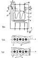
- Figure 2 illustrates the positioning of the three housings 20 inside the tank 2, according to the device of the prior art.
- Standard wall means one of the two walls which are perpendicular at the bottom 12 of the tank 2 and which are parallel to the plane P including the axes of phase winding revolution 10.
- the third box 20, to be placed in the tank 2 involves an additional of volume V of tank 2, as shown in Figure 2.
- Figures 3 and 4 show the positioning of the three phases supplying a transformer comprising a protection device according to the invention. As we will now explain it, the layout is optimized so as to reduce the size of the device.
- Two of the housings 20, corresponding to two of the three phases, are positioned, as before, in the space between two windings of phase 10 and a side wall 11 of the tank 2.
- the third phase is not fitted with a fuse, the bushing 26 corresponding is directly extended by a conductor 14 surrounded by a insulator 15 which also covers the live parts of the end lower of said crossing 26.
- the insulation of said live part is insured even in the absence of liquid dielectric, following a leak for example.
- the phase not provided with a fuse will be the middle phase, that is to say the phase supplying the transformer 1 through the middle crossing 26.
- This conductor 14 because of its small size, can be placed between the side wall 11 of the tank 2 and a winding 10, as shown in the figure 3.
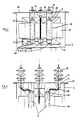
- the spacing of bushings 28 is greater than the spacing authorized boxes 20.
- the electrical connection between the bushings porcelain 28 and fuse 9 is provided by an insulated cable 18 connected to a part to a conductive rod 19 internal to the bushing 28, and secondly to the tulip 25 linked to the upstream of the fuse 9. This cable 18 passes through the wall of the housing 20.
Abstract
- des moyens de déconnexion (6) branchés en série respectivement avec chaque phase, et un système de blocage en position connectée, comportant des premiers moyens de blocage (8),
- un moyen de détection (5) d'un courant de terre circulant entre la terre (3) et la masse de la partie active (4) du transformateur (1),
seuls deux moyens de déconnexion (6) comprenant un élément de sécurité (9).
Description
- si le régime de neutre du réseau moyenne tension est tel que le courant de défaut monophasé peut être supérieur à des valeurs de l'ordre de 250 A, pour une tension entre phases assignée du réseau de l'ordre de 20 kV ;
- si la probabilité de l'occurrence de défauts doubles à la terre est suffisamment importante pour devoir être prise en compte. Dans ce cas, si l'un des défauts transite dans le transformateur entre une première phase et la terre, et si le second défaut transite entre une seconde phase du réseau et la terre, en un point plus ou moins éloigné du transformateur, la valeur du courant de défaut dans le transformateur se rapproche de celle d'un défaut biphasé, et peut atteindre couramment 2000 A.
- si le régime de neutre du réseau moyenne tension est impédant et limite le courant de défaut monophasé à moins de 250 A, et si la probabilité d'occurrence d'un défaut double sur le réseau transitant par le transformateur est considérée comme suffisamment faible pour être négligeable ;
- si le disjoncteur situé au poste source duquel dépend le réseau d'alimentation fonctionne selon des cycles de déclenchement-réenclenchement.
- un système de déconnexion desdites phases comportant d'une part des moyens de déconnexion branchés en série respectivement avec chaque phase, et d'autre part un système de blocage en position connectée, ledit système de blocage comportant des premiers moyens de blocage couplés respectivement aux moyens de déconnexion,
- un moyen de détection d'un courant de terre circulant entre la terre et la masse de la partie active du transformateur.
- la figure 1 est une représentation schématique d'un transformateur comportant un dispositif selon l'invention ;
- la figure 2 est une représentation schématique en coupe transversale d'un transformateur comportant un dispositif de protection conforme à l'art antérieur ;
- la figure 3 est une représentation schématique en coupe transversale d'un transformateur comportant un dispositif de protection selon l'invention ;
- la figure 4 est une vue en élévation de l'intérieur d'un transformateur comprenant un dispositif de protection selon l'invention ;
- la figure 5 est une vue partielle de l'intérieur d'un transformateur équipé de traversées en porcelaine et comprenant un dispositif de protection selon l'invention.
- d'économiser un fusible moyenne tension et les moyens d'isolement qui lui sont associés, ce qui représente une part significative du coût du dispositif global de protection ;
- de réduire le volume de la cuve, ce qui se traduit également par une diminution de la quantité de diélectrique nécessaire.
Claims (7)
- Dispositif de protection contre des effets des défauts internes d'un transformateur de distribution (1) triphasé, ledit transformateur (1) étant destiné à être immergé dans un liquide diélectrique contenu dans une cuve (2) reliée à la terre (3) et à une masse de la partie active (4) du transformateur (1), ledit transformateur (1) comprenant :le moyen de détection du courant de terre commandant le système de blocage lorsqu'un courant de terre est détecté de sorte que le système de déconnexion est placé en position déconnectée,un système de déconnexion desdites phases comportant d'une part des moyens de déconnexion (6) branchés en série respectivement avec chaque phase, et d'autre part un système de blocage en position connectée, ledit système de blocage comportant des premiers moyens de blocage (8) couplés respectivement aux moyens de déconnexion (6),un moyen de détection (5) d'un courant de terre circulant entre la terre (3) et la masse de la partie active (4) du transformateur (1),
caractérisé en ce que seuls deux moyens de déconnexion (6) comprennent un élément de sécurité (9). - Dispositif selon la revendication 1, caractérisé en ce que seuls les deux moyens de déconnexion (6) comportant un élément de sécurité (9) sont montés dans un boítier (20) isolant.
- Dispositif selon la revendication 1 ou 2, caractérisé en ce que les deux boítiers isolants (20) sont positionnés à l'intérieur de la cuve (2) dans les espaces compris entre deux enroulements de phase (10) du transformateur (1) et une paroi latérale (11) de la cuve (2).
- Dispositif selon l'une quelconque des revendications 1 à 3, caractérisé en ce que le moyen de déconnexion (6) ne comprenant pas d'élément de sécurité (9) est branché sur la phase médiane.
- Dispositif selon l'une quelconque des revendications 1 à 4, caractérisé en ce que la phase ne comportant pas d'élément de sécurité (9) comprend un simple conducteur (14) reliant la traversée amont (26) correspondante du transformateur (1) et le premier moyen de blocage (8) correspondant, ledit conducteur (14) étant positionné à l'intérieur de la cuve (2) entre la paroi latérale (11) de la cuve (2) et l'enroulement de phase correspondant.
- Transformateur triphasé (1) de distribution d'énergie électrique moyenne tension destiné à être immergé dans un liquide diélectrique contenu dans une cuve (2), caractérisé en ce qu'il comporte un dispositif de protection selon l'une quelconque des revendications 1 à 5.
- Transformateur triphasé (1) selon la revendication 6 comportant des traversées moyenne tension en porcelaine (28), caractérisé en ce que les traversées correspondant aux deux phases munies d'un élément de sécurité (9) sont électriquement reliées audit élément de sécurité (9) correspondant par un conducteur pénétrant dans le boítier (20) et raccordé à un contact (25) positionné sur l'amont de l'élément de sécurité (9).
Applications Claiming Priority (2)
| Application Number | Priority Date | Filing Date | Title |
|---|---|---|---|
| FR0001188A FR2804549B1 (fr) | 2000-01-31 | 2000-01-31 | Dispositif de protection perfectionne contre les effets des defauts internes d'un transformateur diphase |
| FR0001188 | 2000-01-31 |
Publications (2)
| Publication Number | Publication Date |
|---|---|
| EP1122848A1 true EP1122848A1 (fr) | 2001-08-08 |
| EP1122848B1 EP1122848B1 (fr) | 2011-02-23 |
Family
ID=8846482
Family Applications (1)
| Application Number | Title | Priority Date | Filing Date |
|---|---|---|---|
| EP00403420A Expired - Lifetime EP1122848B1 (fr) | 2000-01-31 | 2000-12-06 | Dispositif de protection perfectionne contre les effects des défauts internes d'un transformateur triphase |
Country Status (5)
| Country | Link |
|---|---|
| EP (1) | EP1122848B1 (fr) |
| AT (1) | ATE499736T1 (fr) |
| DE (1) | DE60045657D1 (fr) |
| ES (1) | ES2363209T3 (fr) |
| FR (1) | FR2804549B1 (fr) |
Cited By (9)
| Publication number | Priority date | Publication date | Assignee | Title |
|---|---|---|---|---|
| FR2854725A1 (fr) * | 2003-05-09 | 2004-11-12 | Alstom | Dispositif de protection d'un transformateur de distribution a isolation dans un dielectrique liquide |
| WO2007133169A1 (fr) * | 2006-05-12 | 2007-11-22 | Great Man Made River Co. For Reclamation And Construction | Description du dispositif de sécurité électrique electro-ageeb |
| FR2915632A1 (fr) * | 2007-04-24 | 2008-10-31 | Transfix Toulon Sa Sa Soc Nouv | Procede et dispositif de protection electrique des liaisons avales d'un transformateur, ainsi que poste de transformation equipe d'un tel dispositif |
| EP2031725A1 (fr) | 2007-09-03 | 2009-03-04 | Societe Nouvelle Transfix Toulon | Dispositif de protection contre des effets de défauts d'isolement dans un appareil électrique polyphasé alimenté par un réseau électrique |
| FR2936909A1 (fr) * | 2008-10-08 | 2010-04-09 | Matelec S A L | Systeme de protection pour transformateur electrique polyphase et transformateur electique comprenant un tel systeme de protection |
| EP2221838A1 (fr) | 2009-02-19 | 2010-08-25 | Societe Nouvelle Transfix Toulon | Procédé, dispositif et système de protection d'un appareil électrique, ainsi que transformateur et poste comportant un tel dispositif ou système |
| EP2282322A1 (fr) * | 2009-08-07 | 2011-02-09 | ABB Technology AG | Sectionneur pour équipement d'alimentation électrique rempli de liquide diélectrique |
| EP2509082A1 (fr) * | 2011-04-07 | 2012-10-10 | ABB Technology AG | Bobine haute tension isolée contre les fluides |
| FR2999792A1 (fr) * | 2012-12-19 | 2014-06-20 | Transfix | Dispositif de protection d'un appareil electronique alimente par un reseau polyphase |
Citations (2)
| Publication number | Priority date | Publication date | Assignee | Title |
|---|---|---|---|---|
| EP0800251A1 (fr) * | 1996-04-04 | 1997-10-08 | Gec Alsthom T & D Sa | Système de protection d'un transformateur de distribution triphasé à isolation dans un diélectrique liquide |
| EP0817346A1 (fr) * | 1996-07-02 | 1998-01-07 | Société Nouvelle Transfix | Dispositif de protection contre les effets des défauts internes d'un appareil électrique |
-
2000
- 2000-01-31 FR FR0001188A patent/FR2804549B1/fr not_active Expired - Lifetime
- 2000-12-06 DE DE60045657T patent/DE60045657D1/de not_active Expired - Lifetime
- 2000-12-06 ES ES00403420T patent/ES2363209T3/es not_active Expired - Lifetime
- 2000-12-06 AT AT00403420T patent/ATE499736T1/de not_active IP Right Cessation
- 2000-12-06 EP EP00403420A patent/EP1122848B1/fr not_active Expired - Lifetime
Patent Citations (3)
| Publication number | Priority date | Publication date | Assignee | Title |
|---|---|---|---|---|
| EP0800251A1 (fr) * | 1996-04-04 | 1997-10-08 | Gec Alsthom T & D Sa | Système de protection d'un transformateur de distribution triphasé à isolation dans un diélectrique liquide |
| EP0817346A1 (fr) * | 1996-07-02 | 1998-01-07 | Société Nouvelle Transfix | Dispositif de protection contre les effets des défauts internes d'un appareil électrique |
| FR2750809A1 (fr) * | 1996-07-02 | 1998-01-09 | Transfix Soc Nouv | Dispositif de protection contre des effets des defauts internes d'un appareil electrique |
Cited By (21)
| Publication number | Priority date | Publication date | Assignee | Title |
|---|---|---|---|---|
| FR2854725A1 (fr) * | 2003-05-09 | 2004-11-12 | Alstom | Dispositif de protection d'un transformateur de distribution a isolation dans un dielectrique liquide |
| WO2004102764A1 (fr) * | 2003-05-09 | 2004-11-25 | Areva T & D Sa | Dispositif de protection d'un transformateur de distribution multiphase, a isolation dans un dielectrique liquide |
| WO2007133169A1 (fr) * | 2006-05-12 | 2007-11-22 | Great Man Made River Co. For Reclamation And Construction | Description du dispositif de sécurité électrique electro-ageeb |
| GB2452203A (en) * | 2006-05-12 | 2009-02-25 | Great Man Made River Co For Re | Description electro-ageeb electrical safety device |
| FR2915632A1 (fr) * | 2007-04-24 | 2008-10-31 | Transfix Toulon Sa Sa Soc Nouv | Procede et dispositif de protection electrique des liaisons avales d'un transformateur, ainsi que poste de transformation equipe d'un tel dispositif |
| EP2031725A1 (fr) | 2007-09-03 | 2009-03-04 | Societe Nouvelle Transfix Toulon | Dispositif de protection contre des effets de défauts d'isolement dans un appareil électrique polyphasé alimenté par un réseau électrique |
| FR2920603A1 (fr) * | 2007-09-03 | 2009-03-06 | Transfix Toulon Sa Sa Soc Nouv | Dispositif de protection contre des effets de defauts d'isolement dans un appareil electrique polyphase alimente par un reseau electrique |
| FR2936909A1 (fr) * | 2008-10-08 | 2010-04-09 | Matelec S A L | Systeme de protection pour transformateur electrique polyphase et transformateur electique comprenant un tel systeme de protection |
| EP2221838A1 (fr) | 2009-02-19 | 2010-08-25 | Societe Nouvelle Transfix Toulon | Procédé, dispositif et système de protection d'un appareil électrique, ainsi que transformateur et poste comportant un tel dispositif ou système |
| WO2011015263A1 (fr) * | 2009-08-07 | 2011-02-10 | Abb Technology Ag | Sectionneur pour équipement de puissance électrique rempli de liquide diélectrique |
| EP2282322A1 (fr) * | 2009-08-07 | 2011-02-09 | ABB Technology AG | Sectionneur pour équipement d'alimentation électrique rempli de liquide diélectrique |
| CN102484021A (zh) * | 2009-08-07 | 2012-05-30 | Abb技术有限公司 | 填充有介电液体的电力设备的隔离开关 |
| US8692645B2 (en) | 2009-08-07 | 2014-04-08 | Abb Technology Ag | Disconnector for electric power equipment filled with dielectric liquid |
| CN102484021B (zh) * | 2009-08-07 | 2014-12-10 | Abb技术有限公司 | 填充有介电液体的电力设备的隔离开关 |
| US9368310B2 (en) | 2009-08-07 | 2016-06-14 | Abb Technology Ag | Disconnector for electric power equipment filled with dielectric liquid |
| EP2509082A1 (fr) * | 2011-04-07 | 2012-10-10 | ABB Technology AG | Bobine haute tension isolée contre les fluides |
| WO2012136302A1 (fr) * | 2011-04-07 | 2012-10-11 | Abb Technology Ag | Bobine haute tension isolée à fluide |
| CN103597559A (zh) * | 2011-04-07 | 2014-02-19 | Abb技术有限公司 | 流体绝缘的高压线圈 |
| US9058926B2 (en) | 2011-04-07 | 2015-06-16 | Abb Technology Ag | Fluid insulated high voltage coil |
| CN103597559B (zh) * | 2011-04-07 | 2016-08-24 | Abb技术有限公司 | 流体绝缘的高压线圈组 |
| FR2999792A1 (fr) * | 2012-12-19 | 2014-06-20 | Transfix | Dispositif de protection d'un appareil electronique alimente par un reseau polyphase |
Also Published As
| Publication number | Publication date |
|---|---|
| FR2804549B1 (fr) | 2002-08-09 |
| ES2363209T3 (es) | 2011-07-27 |
| ATE499736T1 (de) | 2011-03-15 |
| FR2804549A1 (fr) | 2001-08-03 |
| EP1122848B1 (fr) | 2011-02-23 |
| DE60045657D1 (de) | 2011-04-07 |
Similar Documents
| Publication | Publication Date | Title |
|---|---|---|
| EP1304785B1 (fr) | Système de protection d'un transformateur de distribution polyphasé à isolation dans un diélectrique liquide, comportant au moins un interrupteur sectionneur de phase | |
| CA2083297C (fr) | Disjoncteur auto-sectionneur a moyenne tension et application a une cellule et a un poste a moyenne tension | |
| EP0817346B1 (fr) | Dispositif de protection contre les effets des défauts internes d'un appareil électrique | |
| EP0981140B1 (fr) | Transformateur immerge auto-protege par un dispositif incluant un disjoncteur et des fusibles | |
| EP1122848B1 (fr) | Dispositif de protection perfectionne contre les effects des défauts internes d'un transformateur triphase | |
| FR2999792A1 (fr) | Dispositif de protection d'un appareil electronique alimente par un reseau polyphase | |
| FR2948490A1 (fr) | Dispositif de protection d'une installation electrique contre des surtensions transitoires | |
| FR2759212A1 (fr) | Coupe-circuit destine a deconnecter un appareil electrique d'un reseau electrique | |
| FR3072826B1 (fr) | Appareil de coupure electrique, procede et installation utilisant un tel appareil | |
| EP1684394A1 (fr) | Poste de transformation électrique moyenne tension/basse tension | |
| EP0277848B1 (fr) | Disjoncteur polyphasé à autoexpansion équipé d'une chambre de coupure blindée par pole | |
| EP0130851B1 (fr) | Appareil de protection contre les surtensions pour une installation ou un réseau électrique à basse tension | |
| EP0204594A1 (fr) | Appareil interrupteur protégé contre les courants de court-circuit | |
| FR3026239A1 (fr) | Appareillage de protection electrique moyenne tension a comptage du courant | |
| EP1102379A1 (fr) | Système de protection d'un transformateur de distribution triphasé à isolation dans un diélectrique liquide comportant un micro-sectionneur | |
| EP2599100A1 (fr) | Systeme de protection pour transformateur electrique | |
| EP0338382A1 (fr) | Cellule pour poste blindé à moyenne et haute tension et poste constitué de telles cellules | |
| FR3035750A1 (fr) | Dispositif de protection d'un reseau electrique | |
| EP2200060B1 (fr) | Cellule de distribution électrique moyenne tension | |
| WO2004102764A1 (fr) | Dispositif de protection d'un transformateur de distribution multiphase, a isolation dans un dielectrique liquide | |
| FR2629263A1 (fr) | Dispositif de protection pour appareil electrique a moyenne tension | |
| EP2628221B1 (fr) | Dispositif sectionneur de terre et poste electrique haute tension comprenant un tel dispositif | |
| FR2627324A1 (fr) | Disjoncteur differentiel a neutre passant | |
| EP2743957B1 (fr) | Appareil de coupure de courant électrique, en particulier un disjoncteur de branchement | |
| EP3029476B1 (fr) | Procédé pour tester l'ensemble de la chaîne de protection dans un appareillage de protection électrique moyenne tension, et appareillage pour la mise en oeuvre d'un tel procédé. |
Legal Events
| Date | Code | Title | Description |
|---|---|---|---|
| PUAI | Public reference made under article 153(3) epc to a published international application that has entered the european phase |
Free format text: ORIGINAL CODE: 0009012 |
|
| AK | Designated contracting states |
Kind code of ref document: A1 Designated state(s): AT BE CH CY DE DK ES FI FR GB GR IE IT LI LU MC NL PT SE TR |
|
| AX | Request for extension of the european patent |
Free format text: AL;LT;LV;MK;RO;SI |
|
| 17P | Request for examination filed |
Effective date: 20020129 |
|
| AKX | Designation fees paid |
Free format text: AT BE CH CY DE DK ES FI FR GB GR IE IT LI LU MC NL PT SE TR |
|
| 17Q | First examination report despatched |
Effective date: 20090309 |
|
| GRAP | Despatch of communication of intention to grant a patent |
Free format text: ORIGINAL CODE: EPIDOSNIGR1 |
|
| GRAS | Grant fee paid |
Free format text: ORIGINAL CODE: EPIDOSNIGR3 |
|
| GRAA | (expected) grant |
Free format text: ORIGINAL CODE: 0009210 |
|
| AK | Designated contracting states |
Kind code of ref document: B1 Designated state(s): AT BE CH CY DE DK ES FI FR GB GR IE IT LI LU MC NL PT SE TR |
|
| REG | Reference to a national code |
Ref country code: GB Ref legal event code: FG4D Free format text: NOT ENGLISH |
|
| REG | Reference to a national code |
Ref country code: CH Ref legal event code: EP |
|
| REG | Reference to a national code |
Ref country code: IE Ref legal event code: FG4D Free format text: LANGUAGE OF EP DOCUMENT: FRENCH |
|
| REF | Corresponds to: |
Ref document number: 60045657 Country of ref document: DE Date of ref document: 20110407 Kind code of ref document: P |
|
| REG | Reference to a national code |
Ref country code: DE Ref legal event code: R096 Ref document number: 60045657 Country of ref document: DE Effective date: 20110407 |
|
| REG | Reference to a national code |
Ref country code: SE Ref legal event code: TRGR |
|
| REG | Reference to a national code |
Ref country code: NL Ref legal event code: VDEP Effective date: 20110223 |
|
| REG | Reference to a national code |
Ref country code: ES Ref legal event code: FG2A Ref document number: 2363209 Country of ref document: ES Kind code of ref document: T3 Effective date: 20110727 |
|
| PG25 | Lapsed in a contracting state [announced via postgrant information from national office to epo] |
Ref country code: PT Free format text: LAPSE BECAUSE OF FAILURE TO SUBMIT A TRANSLATION OF THE DESCRIPTION OR TO PAY THE FEE WITHIN THE PRESCRIBED TIME-LIMIT Effective date: 20110623 Ref country code: GR Free format text: LAPSE BECAUSE OF FAILURE TO SUBMIT A TRANSLATION OF THE DESCRIPTION OR TO PAY THE FEE WITHIN THE PRESCRIBED TIME-LIMIT Effective date: 20110524 |
|
| PG25 | Lapsed in a contracting state [announced via postgrant information from national office to epo] |
Ref country code: CY Free format text: LAPSE BECAUSE OF FAILURE TO SUBMIT A TRANSLATION OF THE DESCRIPTION OR TO PAY THE FEE WITHIN THE PRESCRIBED TIME-LIMIT Effective date: 20110223 Ref country code: AT Free format text: LAPSE BECAUSE OF FAILURE TO SUBMIT A TRANSLATION OF THE DESCRIPTION OR TO PAY THE FEE WITHIN THE PRESCRIBED TIME-LIMIT Effective date: 20110223 Ref country code: NL Free format text: LAPSE BECAUSE OF FAILURE TO SUBMIT A TRANSLATION OF THE DESCRIPTION OR TO PAY THE FEE WITHIN THE PRESCRIBED TIME-LIMIT Effective date: 20110223 |
|
| PG25 | Lapsed in a contracting state [announced via postgrant information from national office to epo] |
Ref country code: DK Free format text: LAPSE BECAUSE OF FAILURE TO SUBMIT A TRANSLATION OF THE DESCRIPTION OR TO PAY THE FEE WITHIN THE PRESCRIBED TIME-LIMIT Effective date: 20110223 |
|
| PLBE | No opposition filed within time limit |
Free format text: ORIGINAL CODE: 0009261 |
|
| STAA | Information on the status of an ep patent application or granted ep patent |
Free format text: STATUS: NO OPPOSITION FILED WITHIN TIME LIMIT |
|
| 26N | No opposition filed |
Effective date: 20111124 |
|
| REG | Reference to a national code |
Ref country code: DE Ref legal event code: R097 Ref document number: 60045657 Country of ref document: DE Effective date: 20111124 |
|
| PG25 | Lapsed in a contracting state [announced via postgrant information from national office to epo] |
Ref country code: IT Free format text: LAPSE BECAUSE OF FAILURE TO SUBMIT A TRANSLATION OF THE DESCRIPTION OR TO PAY THE FEE WITHIN THE PRESCRIBED TIME-LIMIT Effective date: 20110223 |
|
| PG25 | Lapsed in a contracting state [announced via postgrant information from national office to epo] |
Ref country code: MC Free format text: LAPSE BECAUSE OF NON-PAYMENT OF DUE FEES Effective date: 20111231 |
|
| REG | Reference to a national code |
Ref country code: CH Ref legal event code: PL |
|
| GBPC | Gb: european patent ceased through non-payment of renewal fee |
Effective date: 20111206 |
|
| PG25 | Lapsed in a contracting state [announced via postgrant information from national office to epo] |
Ref country code: GB Free format text: LAPSE BECAUSE OF NON-PAYMENT OF DUE FEES Effective date: 20111206 Ref country code: LI Free format text: LAPSE BECAUSE OF NON-PAYMENT OF DUE FEES Effective date: 20111231 Ref country code: CH Free format text: LAPSE BECAUSE OF NON-PAYMENT OF DUE FEES Effective date: 20111231 |
|
| PG25 | Lapsed in a contracting state [announced via postgrant information from national office to epo] |
Ref country code: LU Free format text: LAPSE BECAUSE OF NON-PAYMENT OF DUE FEES Effective date: 20111206 |
|
| REG | Reference to a national code |
Ref country code: FR Ref legal event code: CA Effective date: 20131129 Ref country code: FR Ref legal event code: CD Owner name: TRANSFIX, FR Effective date: 20131129 |
|
| REG | Reference to a national code |
Ref country code: DE Ref legal event code: R081 Ref document number: 60045657 Country of ref document: DE Owner name: TRANSFIX, FR Free format text: FORMER OWNER: SOCIETE NOUVELLE TRANSFIX TOULON, CAHORS, FR Effective date: 20140312 |
|
| REG | Reference to a national code |
Ref country code: ES Ref legal event code: PC2A Owner name: TRANSFIX Effective date: 20140416 |
|
| REG | Reference to a national code |
Ref country code: FR Ref legal event code: PLFP Year of fee payment: 16 |
|
| REG | Reference to a national code |
Ref country code: FR Ref legal event code: PLFP Year of fee payment: 17 |
|
| PGFP | Annual fee paid to national office [announced via postgrant information from national office to epo] |
Ref country code: TR Payment date: 20161124 Year of fee payment: 17 |
|
| REG | Reference to a national code |
Ref country code: FR Ref legal event code: PLFP Year of fee payment: 18 |
|
| PGFP | Annual fee paid to national office [announced via postgrant information from national office to epo] |
Ref country code: FI Payment date: 20191230 Year of fee payment: 20 Ref country code: SE Payment date: 20191224 Year of fee payment: 20 Ref country code: IE Payment date: 20191230 Year of fee payment: 20 |
|
| PGFP | Annual fee paid to national office [announced via postgrant information from national office to epo] |
Ref country code: FR Payment date: 20191227 Year of fee payment: 20 |
|
| PGFP | Annual fee paid to national office [announced via postgrant information from national office to epo] |
Ref country code: ES Payment date: 20200122 Year of fee payment: 20 Ref country code: DE Payment date: 20191224 Year of fee payment: 20 |
|
| PGFP | Annual fee paid to national office [announced via postgrant information from national office to epo] |
Ref country code: BE Payment date: 20200102 Year of fee payment: 20 |
|
| REG | Reference to a national code |
Ref country code: DE Ref legal event code: R071 Ref document number: 60045657 Country of ref document: DE |
|
| REG | Reference to a national code |
Ref country code: FI Ref legal event code: MAE |
|
| REG | Reference to a national code |
Ref country code: BE Ref legal event code: MK Effective date: 20201206 Ref country code: IE Ref legal event code: MK9A |
|
| REG | Reference to a national code |
Ref country code: ES Ref legal event code: FD2A Effective date: 20210326 |
|
| PG25 | Lapsed in a contracting state [announced via postgrant information from national office to epo] |
Ref country code: IE Free format text: LAPSE BECAUSE OF EXPIRATION OF PROTECTION Effective date: 20201206 |
|
| PG25 | Lapsed in a contracting state [announced via postgrant information from national office to epo] |
Ref country code: ES Free format text: LAPSE BECAUSE OF EXPIRATION OF PROTECTION Effective date: 20201207 |
|
| REG | Reference to a national code |
Ref country code: SE Ref legal event code: EUG |
|
| PG25 | Lapsed in a contracting state [announced via postgrant information from national office to epo] |
Ref country code: TR Free format text: LAPSE BECAUSE OF NON-PAYMENT OF DUE FEES Effective date: 20171206 |