EP1122438A2 - Accouplement Oldham pour machine à spirales - Google Patents
Accouplement Oldham pour machine à spirales Download PDFInfo
- Publication number
- EP1122438A2 EP1122438A2 EP01300940A EP01300940A EP1122438A2 EP 1122438 A2 EP1122438 A2 EP 1122438A2 EP 01300940 A EP01300940 A EP 01300940A EP 01300940 A EP01300940 A EP 01300940A EP 1122438 A2 EP1122438 A2 EP 1122438A2
- Authority
- EP
- European Patent Office
- Prior art keywords
- post
- scroll
- face
- oldham coupling
- scroll member
- Prior art date
- Legal status (The legal status is an assumption and is not a legal conclusion. Google has not performed a legal analysis and makes no representation as to the accuracy of the status listed.)
- Granted
Links
Images


Classifications
-
- F—MECHANICAL ENGINEERING; LIGHTING; HEATING; WEAPONS; BLASTING
- F04—POSITIVE - DISPLACEMENT MACHINES FOR LIQUIDS; PUMPS FOR LIQUIDS OR ELASTIC FLUIDS
- F04C—ROTARY-PISTON, OR OSCILLATING-PISTON, POSITIVE-DISPLACEMENT MACHINES FOR LIQUIDS; ROTARY-PISTON, OR OSCILLATING-PISTON, POSITIVE-DISPLACEMENT PUMPS
- F04C18/00—Rotary-piston pumps specially adapted for elastic fluids
- F04C18/02—Rotary-piston pumps specially adapted for elastic fluids of arcuate-engagement type, i.e. with circular translatory movement of co-operating members, each member having the same number of teeth or tooth-equivalents
-
- F—MECHANICAL ENGINEERING; LIGHTING; HEATING; WEAPONS; BLASTING
- F01—MACHINES OR ENGINES IN GENERAL; ENGINE PLANTS IN GENERAL; STEAM ENGINES
- F01C—ROTARY-PISTON OR OSCILLATING-PISTON MACHINES OR ENGINES
- F01C17/00—Arrangements for drive of co-operating members, e.g. for rotary piston and casing
- F01C17/06—Arrangements for drive of co-operating members, e.g. for rotary piston and casing using cranks, universal joints or similar elements
- F01C17/066—Arrangements for drive of co-operating members, e.g. for rotary piston and casing using cranks, universal joints or similar elements with an intermediate piece sliding along perpendicular axes, e.g. Oldham coupling
Definitions
- the present invention relates generally to scroll machines. More particularly, the present invention relates to a unique Oldham coupling design for use in these scroll machines.
- a class of machines exists in the art generally known as "scroll" machines which are used for the displacement of various types of fluids. Such machines may be configured as an expander, a displacement engine, a pump, a compressor, etc., and the features of the present invention are applicable to any one of these machines. For purposes of illustration, however, the disclosed embodiments are in the form of a hermetic refrigerant compressor.
- a scroll apparatus comprises two spiral scroll wraps of similar configuration, each mounted on a separate end plate to define a scroll member.
- the two scroll members are interfitted together with one of the scroll wraps being rotationally displaced 180 degrees from the other.
- the machine operates by orbiting one scroll member (the orbiting scroll) with respect to the other scroll member (the non-orbiting scroll) to produce moving line contacts between the flanks of the respective wraps. These moving line contacts define moving isolated crescent-shaped pockets of fluid.
- the spiral scroll wraps are commonly formed as involutes of a circle. Ideally, there is no relative rotation between the scroll members during operation, the motion is purely curvilinear translation (no rotation of any line of the body). The relative rotation between the scroll members is typically prohibited by the use of an Oldham coupling.
- the moving fluid pockets carry the fluid to be handled from a first zone in the scroll machine where a fluid inlet is provided, to a second zone in the scroll machine where a fluid outlet is provided.
- the volume of the sealed pocket changes as it moves from the first zone to the second zone.
- the second zone is at a higher pressure than the first zone and is physically located centrally within the machine, the first zone being located at the outer periphery of the apparatus.
- the Oldham coupling that prohibits the relative rotation between the scroll members has taken various forms but generally incorporate two pairs of keys projecting from an annular ring. One pair of keys engages slots in the orbiting scroll and the other pair of keys engages slots in the non-orbiting scroll member or a stationary body such as a bearing housing.
- Oldham couplings which are connected between the two scroll members are effective to prevent rotation between these respective scroll members, they present design and/or assembly problems in regards to positioning of the coupling between the scroll members.
- additional support structure and/or increased shell'size may be required to support the Oldham coupling radially outwardly of the scroll members.
- the present invention in one embodiment, provides an Oldham coupling which is capable of directly interconnecting the two scroll members so as to effectively prevent relative rotation therebetween while avoiding potential design problems presented by the prior designs and also reducing the number of locating and positioning surfaces required.
- the present invention provides an Oldham coupling which has only one pair of posts for engagement with the scroll members.
- the orbiting scroll member contacts the lower portion of the pair of keys and the non-orbiting scroll member contacts the upper portion of the pair of keys.
- the single pair of keys is attached to an annular ring and in another embodiment the single pair of keys is attached to an arc segment of an annular ring extending between the keys.
- an Oldham coupling directly interconnects the orbiting scroll member with the main bearing housing to prevent rotation of the orbiting scroll member.
- This Oldham coupling also has a single pair of keys for engagement with the orbiting scroll member and the main bearing housing.
- the single pair of keys can be connected to an annular ring or they can be connected to an arc segment of an annular ring.
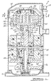
- Scroll compressor 10 comprises a generally cylindrical hermetic shell 12 having welded at the upper end thereof a cap 14 and at the lower end thereof a base 16 having a plurality of mounting feet (not shown) integrally formed therewith.
- Cap 14 is provided with a refrigerant discharge fitting 18 which may have the usual discharge valve therein (not shown).
- a transversely extending partition 22 which is welded about its periphery at the same point that cap 14 is welded to shell 12
- a main bearing housing 24 which is suitably secured to shell 12
- a lower bearing housing 26 having a plurality of radially outwardly extending legs each of which is also suitably secured to shell 12.
- a motor stator 28 which is generally square in cross-section but with the corners rounded off is press fitted into shell 12. The flats between the rounded corners on the stator provide passageways between the stator and shell, which facilitate the return flow of lubricant from the top of the shell to the bottom.
- a drive shaft or crankshaft 30 having an eccentric crank pin 32 at the upper end thereof is rotatably journaled in a bearing 34 in main bearing housing 24 and a second bearing 36 in lower bearing housing 26.
- Crankshaft 30 has at the lower end a relatively large diameter concentric bore 38 which communicates with a radially outwardly inclined smaller diameter bore 40 extending upwardly therefrom to the top of crankshaft 30. Disposed within bore 38 is a stirrer 42.
- the lower portion of the interior shell 12 defines an oil sump 44 which is filled with lubricating oil to a level slightly above the lower end of a rotor 46, and bore 38 acts as a pump to pump lubricating fluid up the crankshaft 30 and into passageway 40 and ultimately to all of the various portions of the compressor which require lubrication.
- Crankshaft 30 is rotatively driven by an electric motor including stator 28, windings 48 passing therethrough and rotor 46 press fitted on crankshaft 30 and having upper and lower counterweights 50 and 52, respectively.
- main bearing housing 24 The upper surface of main bearing housing 24 is provided with a flat thrust bearing surface 54 on which is disposed an orbiting scroll member 56 having the usual spiral vane or wrap 58 extending upward from an end plate 60.
- an orbiting scroll member 56 Projecting downwardly from the lower surface of end plate 60 of orbiting scroll member 56 is a cylindrical hub having a journal bearing 62 therein and in which is rotatively disposed a drive bushing 64 having an inner bore 66 in which crank pin 32 is drivingly disposed.
- Crank pin 32 has a flat on one surface which drivingly engages a flat surface (not shown) formed in a portion of bore 66 to provide a radially compliant driving arrangement, such as shown in assignee's U.S.
- An Oldham coupling 68 is also provided positioned between orbiting scroll member 56 and bearing housing 24 and keyed to orbiting scroll member 56 and a non-orbiting scroll member 70 to prevent rotational movement of orbiting scroll member 56.
- Non-orbiting scroll member 70 is also provided having a wrap 72 extending downwardly from an end plate 74 which is positioned in meshing engagement with wrap 58 of orbiting scroll member 56.
- Non-orbiting scroll member 70 has a centrally disposed discharge passage 76 which communicates with an upwardly open recess 78 which in turn is in fluid communication with a discharge muffler chamber 80 defined by cap 14 and partition 22.
- An annular recess 82 is also formed in non-orbiting scroll member 70 within which is disposed a seal assembly 84.
- Recesses 78 and 82 and seal assembly 84 cooperate to define axial pressure biasing chambers which receive pressurized fluid being compressed by wraps 58 and 72 so as to exert an axial biasing force on non-orbiting scroll member 70 to thereby urge the tips of respective wraps 58, 72 into sealing engagement with the opposed end plate surfaces of end plates 74 and 60, respectively.
- Seal assembly 84 is preferably of the type described in greater detail in U.S. Patent No. 5,156,539, the disclosure of which is hereby incorporated herein by reference.
- Nonorbiting scroll member 70 is designed to be mounted to bearing housing 24 in a suitable manner such as disclosed in the aforementioned U.S. Patent No. 4,877,382 or U.S. Patent No. 5,102,316, the disclosure of which is hereby incorporated herein by reference.
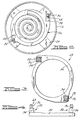
- Oldham coupling 68 comprises a ring 90 having two upwardly projecting diametrically opposing integral posts 92. Each post 92 includes an orbiting scroll engagement key 94 and a non-orbiting scroll engagement key 96. As shown in Figures 1 and 2, ring 90 is disposed between orbiting scroll member 56 and main bearing housing 24 with posts 92 extending through respective slots 98 in orbiting scroll member 56 for engagement with key 94 and respective slots 100 in non-orbiting scroll member 70 for engagement with keys 96.
- Oldham coupling 68 has posts 92 and thus keys 94 and 96 rotated a specified number of degrees, preferably between 30 and 60 degrees.
- one post 92 is rotated 55° and the other post 92 is rotated 57° from the horizontal axis as shown in Figure 3.
- slots 98 and 100 accordingly, all four faces of posts 92 can be used to resist a moment.
- Orbiting scroll member 56 utilizes two opposed faces of key 94 at an elevation proximate to ring 90 while non-orbiting scroll member 70 utilizes the other two opposed faces of key 96 at an elevation distal to ring 90.
- Four keys, two each of keys 94 and 96, are provided for engagement with scroll members 56 and 70 but only two posts 92 are required. This design is more compact, lower weight and lower cost.
- Oldham coupling 168 in accordance with another embodiment of the present invention is illustrated.
- Oldham coupling 168 comprises a curved bar 190 having two upwardly projecting diametrically opposing integral posts 192 positioned at opposing sides of curved bar 190.
- Each post 192 includes an orbiting scroll engagement key 194 and a non-orbiting scroll engagement key 196.
- Curved bar 190 is designed to be disposed between orbiting scroll member 56 and main bearing housing 24 with posts 192 extending through slots 98 in orbiting scroll member 56 for engagement with keys 194 and extending through slots 100 in non-orbiting scroll 70 for engagement with keys 196.
- Oldham coupling 168 has posts 192 and thus keys 194 and 196 rotated similar to that of keys 94 and 96. Thus, all four faces of posts 192 can be used to resist a moment. This allows non-orbiting scroll member 70 and orbiting scroll member 56 to use the same post. Orbiting scroll member 56 utilizes two opposed faces of key 194 at an elevation proximate to curved bar 190 while non-orbiting scroll member 70 utilizes the other two opposed faces of key 196 at an elevation distal to curved bar 190.
- Four keys, two each of keys 194 and 196, are provided for engagement with scroll members 56 and 70 but only two posts 192 are required. This design is more compact, lower weight and lower cost.
- FIG. 7 an Oldham coupling 268 in accordance with another embodiment of the present invention is illustrated.
- the embodiments illustrated in Figures 1-6 all show the Oldham coupling being keyed to both the non-orbiting scroll and the orbiting scroll.
- Another option that is available to the designer of scroll compressors is to key the Oldham coupling between the compressor body (i.e., the main bearing housing) and the orbiting scroll.
- This design for the Oldham coupling has both its advantages and its disadvantages as is well known in the art.
- a main bearing housing 224 has been adapted for mating with Oldham coupling 268.
- Oldham coupling 268 comprises a ring 290 having two upwardly projecting diametrically opposing integral posts 292.
- Each post 292 includes an orbiting scroll engagement key 294 and a main bearing housing engagement key 296.
- ring 290 is disposed between orbiting scroll member 56 and main bearing housing 224 with posts 292 extending upward through respective slots 98 in orbiting scroll member 56 for engagement with keys 294 at a point distal from ring 290 and with posts 292 extending upward through respective slots 300 in main bearing housing 224 for engagement with keys 296 at a point proximate to ring 290.
- Oldham coupling 268 has posts 292 and thus keys 294 and 296 rotated similar to that of keys 94 and 96. Thus, by arranging slots 98 and 300 accordingly, all four faces of posts 292 can be used to resist a moment. This allows main bearing housing 224 and orbiting scroll member 56 to use the same post. Orbiting scroll member 56 utilizes two opposed faces of key 294 at a position distal to ring 290 while main bearing housing 224 utilizes the other two opposed faces of key 296 at a position proximate to ring 290.
- Four keys, two each of keys 294 and 296, are provided for engagement with orbiting scroll member 56 and main bearing housing 224 but only two posts 292 are required. This design is more compact, lower weight and lower cost.
- Oldham coupling 368 in accordance with another embodiment of the present invention is illustrated.
- Oldham coupling 368 comprises a curved bar 390 having two upwardly projecting diametrically opposing integral posts 392 positioned at opposing sides of curved bar 390.
- Each post 392 includes an orbiting scroll engagement key 394 and a main bearing housing engagement key 396.
- Curved bar 390 is designed to be disposed between orbiting scroll member 56 and main bearing housing 224 with posts 392 extending upwardly through slots 78 in orbiting scroll member 56 for engagement with keys 394 and extending upwardly through slots 300 in main bearing housing 224 for engagement with keys 396.
- Oldham coupling 368 has posts 392 and thus keys 394 and 396 rotated similar to that of keys 94 and 96. Thus, all four faces of posts 392 can be used to resist a moment. This allows main bearing housing 224 and orbiting scroll member 56 to use the same post. Orbiting scroll member 56 utilizes two opposed faces of key 394 at a position distal to curved bar 390 while main bearing housing 224 utilizes the other two opposed faces of key 396 at a position proximate to curved bar 390. Four keys, two each of keys 394 and 396, are provided for engagement with orbiting scroll member 56 and main bearing housing 224 but only two posts 392 are required. This design is more compact, lower weight and lower cost.
- Oldham coupling 468 in accordance with another embodiment of the present invention is illustrated.
- Oldham coupling 468 is similar to Oldham coupling 268 shown in Figures 7 and 8 in that it is designed to be keyed to main bearing housing 224 and orbiting scroll member 56.
- Oldham coupling 468 comprises a ring 490 having two upwardly/downwardly projecting diametrically opposing integral posts 492.
- Each post 492 includes an orbiting scroll engagement key 494 and a main bearing housing engagement key 496.
- Ring 490 is designed to be located between orbiting scroll member 56 and main bearing housing 224 with posts 492 extending upward through respective slots 98 in orbiting scroll member 56 for engagement with keys 494 and with posts 492 extending downward through respective slots 300 in main bearing housing 224 for engagement with keys 496.
- Oldham coupling 468 has posts 492 and thus keys 494 and 496 rotated similar to that of keys 94 and 96.
- slots 98 and 300 accordingly, all four faces of posts 492 can be used to resist a moment.
- Orbiting scroll member 56 utilizes two opposed faces of key 494 at a position on one side of ring 490 while main bearing housing 224 utilizes the other two opposed faces of key 496 on the other side of ring 480.
- Four keys, two each of keys 494 and 496, are provided for engagement with orbiting scroll member 56 and main bearing housing 224 but only two posts 492 are required. This design is more compact, lower weight and lower cost.
Applications Claiming Priority (2)
| Application Number | Priority Date | Filing Date | Title |
|---|---|---|---|
| US496808 | 2000-02-02 | ||
| US09/496,808 US6231324B1 (en) | 2000-02-02 | 2000-02-02 | Oldham coupling for scroll machine |
Publications (3)
| Publication Number | Publication Date |
|---|---|
| EP1122438A2 true EP1122438A2 (fr) | 2001-08-08 |
| EP1122438A3 EP1122438A3 (fr) | 2006-04-12 |
| EP1122438B1 EP1122438B1 (fr) | 2015-07-01 |
Family
ID=23974222
Family Applications (1)
| Application Number | Title | Priority Date | Filing Date |
|---|---|---|---|
| EP01300940.2A Expired - Lifetime EP1122438B1 (fr) | 2000-02-02 | 2001-02-02 | Accouplement Oldham pour machine à spirales |
Country Status (9)
| Country | Link |
|---|---|
| US (1) | US6231324B1 (fr) |
| EP (1) | EP1122438B1 (fr) |
| JP (1) | JP4689050B2 (fr) |
| KR (1) | KR100845823B1 (fr) |
| CN (1) | CN1206454C (fr) |
| AU (1) | AU771455B2 (fr) |
| BR (1) | BR0100316B1 (fr) |
| MX (1) | MXPA01001070A (fr) |
| TW (1) | TW522203B (fr) |
Cited By (2)
| Publication number | Priority date | Publication date | Assignee | Title |
|---|---|---|---|---|
| CN103032315A (zh) * | 2011-09-30 | 2013-04-10 | 丹佛斯(天津)有限公司 | 用于涡旋压缩机的联轴节和涡旋压缩机 |
| EP3447294A4 (fr) * | 2016-04-18 | 2019-04-17 | Daikin Industries, Ltd. | Compresseur à spirale |
Families Citing this family (15)
| Publication number | Priority date | Publication date | Assignee | Title |
|---|---|---|---|---|
| US6231324B1 (en) * | 2000-02-02 | 2001-05-15 | Copeland Corporation | Oldham coupling for scroll machine |
| US8769982B2 (en) * | 2006-10-02 | 2014-07-08 | Emerson Climate Technologies, Inc. | Injection system and method for refrigeration system compressor |
| US8181478B2 (en) * | 2006-10-02 | 2012-05-22 | Emerson Climate Technologies, Inc. | Refrigeration system |
| US7647790B2 (en) * | 2006-10-02 | 2010-01-19 | Emerson Climate Technologies, Inc. | Injection system and method for refrigeration system compressor |
| US7997883B2 (en) | 2007-10-12 | 2011-08-16 | Emerson Climate Technologies, Inc. | Scroll compressor with scroll deflection compensation |
| US7918658B2 (en) * | 2008-01-17 | 2011-04-05 | Bitzer Scroll Inc. | Non symmetrical key coupling contact and scroll compressor having same |
| WO2011118562A1 (fr) * | 2010-03-24 | 2011-09-29 | サンデン株式会社 | Machine hydraulique |
| JP5282764B2 (ja) * | 2010-06-04 | 2013-09-04 | ダイキン工業株式会社 | スクロール圧縮機 |
| US9377022B2 (en) * | 2013-01-08 | 2016-06-28 | Emerson Climate Technologies, Inc. | Radially compliant scroll compressor |
| US9885347B2 (en) | 2013-10-30 | 2018-02-06 | Emerson Climate Technologies, Inc. | Components for compressors having electroless coatings on wear surfaces |
| JP6098706B1 (ja) * | 2015-12-28 | 2017-03-22 | ダイキン工業株式会社 | スクロール圧縮機 |
| US10400770B2 (en) | 2016-02-17 | 2019-09-03 | Emerson Climate Technologies, Inc. | Compressor with Oldham assembly |
| FR3054274B1 (fr) | 2016-07-25 | 2020-02-07 | Danfoss Commercial Compressors | Joint d'oldham pour un compresseur a spirales |
| CN106168218B (zh) * | 2016-08-24 | 2018-09-07 | 珠海格力节能环保制冷技术研究中心有限公司 | 涡旋压缩机及其压缩机构、动涡旋盘防自转装置 |
| US11136977B2 (en) | 2018-12-31 | 2021-10-05 | Emerson Climate Technologies, Inc. | Compressor having Oldham keys |
Citations (3)
| Publication number | Priority date | Publication date | Assignee | Title |
|---|---|---|---|---|
| US4877382A (en) | 1986-08-22 | 1989-10-31 | Copeland Corporation | Scroll-type machine with axially compliant mounting |
| US5102316A (en) | 1986-08-22 | 1992-04-07 | Copeland Corporation | Non-orbiting scroll mounting arrangements for a scroll machine |
| US5156539A (en) | 1990-10-01 | 1992-10-20 | Copeland Corporation | Scroll machine with floating seal |
Family Cites Families (28)
| Publication number | Priority date | Publication date | Assignee | Title |
|---|---|---|---|---|
| US4121438A (en) | 1976-09-13 | 1978-10-24 | Arthur D. Little, Inc. | Coupling member for orbiting machinery |
| JPS59160083A (ja) * | 1983-03-02 | 1984-09-10 | Hitachi Ltd | スクロ−ル圧縮機用オルダム機構 |
| JPS6152803A (ja) * | 1984-08-23 | 1986-03-15 | 松下電工株式会社 | ヘア−カ−ル器 |
| US4992033A (en) | 1986-08-22 | 1991-02-12 | Copeland Corporation | Scroll-type machine having compact Oldham coupling |
| US5407335A (en) * | 1986-08-22 | 1995-04-18 | Copeland Corporation | Non-orbiting scroll mounting arrangements for a scroll machine |
| JPH0689750B2 (ja) * | 1986-09-30 | 1994-11-14 | 三井精機工業株式会社 | スクロ−ル圧縮機のオルダム継手構造 |
| JPH01102494U (fr) * | 1987-12-25 | 1989-07-11 | ||
| KR950008694B1 (ko) * | 1987-12-28 | 1995-08-04 | 마쯔시다덴기산교 가부시기가이샤 | 스크롤압축기 |
| JP2758193B2 (ja) * | 1989-02-28 | 1998-05-28 | 株式会社東芝 | スクロール流体機械およびスクロール流体機械用オルダム継手 |
| DE69103604T2 (de) * | 1990-10-01 | 1994-12-22 | Copeland Corp | Oldham's Kupplung für Spiralverdichter. |
| JP3360303B2 (ja) * | 1991-09-13 | 2002-12-24 | ダイキン工業株式会社 | スクロール形流体機械 |
| JPH0579474A (ja) | 1991-09-17 | 1993-03-30 | Daido Metal Co Ltd | スクロール型圧縮機のオルダムリングおよびその製造方法 |
| US5281114A (en) * | 1991-12-17 | 1994-01-25 | Carrier Corporation | Dynamically balanced co-orbiting scrolls |
| US5141417A (en) * | 1991-12-17 | 1992-08-25 | Carrier Corporation | Method for dynamically balancing nested coupling mechanisms for scroll machines |
| US5141421A (en) * | 1991-12-17 | 1992-08-25 | Carrier Corporation | Nested coupling mechanism for scroll machines |
| JP2682784B2 (ja) | 1993-02-23 | 1997-11-26 | 大同メタル工業株式会社 | スクロール型圧縮機のオルダムリング |
| US5330334A (en) | 1993-08-26 | 1994-07-19 | Carrier Corporation | Compact Oldham coupling |
| US5403172A (en) * | 1993-11-03 | 1995-04-04 | Copeland Corporation | Scroll machine sound attenuation |
| JP3601073B2 (ja) * | 1994-05-06 | 2004-12-15 | ダイキン工業株式会社 | スクロール形流体機械 |
| US5593295A (en) * | 1995-04-19 | 1997-01-14 | Bristol Compressors, Inc. | Scroll compressor construction having an axial compliance mechanism |
| JPH08319958A (ja) | 1995-05-24 | 1996-12-03 | Sanden Corp | スクロール型流体装置 |
| US5582512A (en) | 1995-07-07 | 1996-12-10 | Carrier Corporation | Compact oldham coupling |
| JPH1089003A (ja) * | 1996-09-20 | 1998-04-07 | Hitachi Ltd | 容積型流体機械 |
| US5897306A (en) * | 1997-04-17 | 1999-04-27 | Copeland Corporation | Partition and pilot ring for scroll machine |
| US6139295A (en) * | 1998-06-22 | 2000-10-31 | Tecumseh Products Company | Bearing lubrication system for a scroll compressor |
| US6231324B1 (en) * | 2000-02-02 | 2001-05-15 | Copeland Corporation | Oldham coupling for scroll machine |
| US6443719B1 (en) * | 2001-02-20 | 2002-09-03 | Scroll Technologies | Easy-manufacture oldham coupling |
| DE10135254C1 (de) * | 2001-07-19 | 2003-09-04 | Danfoss As | Spiralverdichter |
-
2000
- 2000-02-02 US US09/496,808 patent/US6231324B1/en not_active Expired - Lifetime
-
2001
- 2001-01-15 JP JP2001005873A patent/JP4689050B2/ja not_active Expired - Fee Related
- 2001-01-16 TW TW090100949A patent/TW522203B/zh not_active IP Right Cessation
- 2001-01-24 AU AU16428/01A patent/AU771455B2/en not_active Ceased
- 2001-01-29 MX MXPA01001070A patent/MXPA01001070A/es active IP Right Grant
- 2001-02-01 KR KR1020010004828A patent/KR100845823B1/ko active IP Right Grant
- 2001-02-02 BR BRPI0100316-0A patent/BR0100316B1/pt not_active IP Right Cessation
- 2001-02-02 EP EP01300940.2A patent/EP1122438B1/fr not_active Expired - Lifetime
- 2001-02-02 CN CNB011033606A patent/CN1206454C/zh not_active Expired - Lifetime
Patent Citations (3)
| Publication number | Priority date | Publication date | Assignee | Title |
|---|---|---|---|---|
| US4877382A (en) | 1986-08-22 | 1989-10-31 | Copeland Corporation | Scroll-type machine with axially compliant mounting |
| US5102316A (en) | 1986-08-22 | 1992-04-07 | Copeland Corporation | Non-orbiting scroll mounting arrangements for a scroll machine |
| US5156539A (en) | 1990-10-01 | 1992-10-20 | Copeland Corporation | Scroll machine with floating seal |
Cited By (3)
| Publication number | Priority date | Publication date | Assignee | Title |
|---|---|---|---|---|
| CN103032315A (zh) * | 2011-09-30 | 2013-04-10 | 丹佛斯(天津)有限公司 | 用于涡旋压缩机的联轴节和涡旋压缩机 |
| EP3447294A4 (fr) * | 2016-04-18 | 2019-04-17 | Daikin Industries, Ltd. | Compresseur à spirale |
| US10941661B2 (en) | 2016-04-18 | 2021-03-09 | Daikin Industries, Ltd. | Scroll compressor having oldham coupling with key portions projecting from horizontal surfaces into key grooves |
Also Published As
| Publication number | Publication date |
|---|---|
| AU771455B2 (en) | 2004-03-25 |
| KR100845823B1 (ko) | 2008-07-14 |
| US6231324B1 (en) | 2001-05-15 |
| KR20010078244A (ko) | 2001-08-20 |
| EP1122438A3 (fr) | 2006-04-12 |
| JP2001221172A (ja) | 2001-08-17 |
| EP1122438B1 (fr) | 2015-07-01 |
| JP4689050B2 (ja) | 2011-05-25 |
| BR0100316B1 (pt) | 2011-11-01 |
| AU1642801A (en) | 2001-08-09 |
| CN1206454C (zh) | 2005-06-15 |
| MXPA01001070A (es) | 2002-06-04 |
| CN1317643A (zh) | 2001-10-17 |
| BR0100316A (pt) | 2001-10-09 |
| TW522203B (en) | 2003-03-01 |
Similar Documents
| Publication | Publication Date | Title |
|---|---|---|
| EP1122436B1 (fr) | Compresseur à volutes horizontal | |
| US6439867B1 (en) | Scroll compressor having a clearance for the oldham coupling | |
| EP1674846B1 (fr) | Machine à spirales avec contrepoids avec cavité variable | |
| EP0479412A1 (fr) | Accouplement Oldham pour compresseur à spirales | |
| EP0066457B1 (fr) | Mécanisme de support d'entraînement pour une volute rotative d'une machine à déplacement à volutes imbriquées | |
| US6231324B1 (en) | Oldham coupling for scroll machine | |
| EP2295805A1 (fr) | Compresseur à volutes avec injection de vapeur | |
| EP1199474A2 (fr) | Compresseur à spirales | |
| EP1630421B1 (fr) | Pompe de lubrification d'un compresseur | |
| WO2007111903A1 (fr) | Compresseur helicoidal utilisant un joint d'etancheite flottant avec support | |
| US5582511A (en) | Scroll machine having discharge port inserts | |
| US6179591B1 (en) | Conical hub bearing for scroll machine | |
| US5489198A (en) | Scroll machine sound attenuation | |
| AU2012203079B2 (en) | Counterweights for balancing rotary machines | |
| JP2004293533A (ja) | スクロール圧縮機 |
Legal Events
| Date | Code | Title | Description |
|---|---|---|---|
| PUAI | Public reference made under article 153(3) epc to a published international application that has entered the european phase |
Free format text: ORIGINAL CODE: 0009012 |
|
| AK | Designated contracting states |
Kind code of ref document: A2 Designated state(s): AT BE CH CY DE DK ES FI FR GB GR IE IT LI LU MC NL PT SE TR |
|
| AX | Request for extension of the european patent |
Free format text: AL;LT;LV;MK;RO;SI |
|
| PUAL | Search report despatched |
Free format text: ORIGINAL CODE: 0009013 |
|
| AK | Designated contracting states |
Kind code of ref document: A3 Designated state(s): AT BE CH CY DE DK ES FI FR GB GR IE IT LI LU MC NL PT SE TR |
|
| AX | Request for extension of the european patent |
Extension state: AL LT LV MK RO SI |
|
| 17P | Request for examination filed |
Effective date: 20060529 |
|
| AKX | Designation fees paid |
Designated state(s): DE ES FR GB IT |
|
| RAP1 | Party data changed (applicant data changed or rights of an application transferred) |
Owner name: EMERSON CLIMATE TECHNOLOGIES, INC. |
|
| 17Q | First examination report despatched |
Effective date: 20071031 |
|
| REG | Reference to a national code |
Ref country code: DE Ref legal event code: R079 Ref document number: 60149424 Country of ref document: DE Free format text: PREVIOUS MAIN CLASS: F04C0018020000 Ipc: F01C0017060000 |
|
| GRAP | Despatch of communication of intention to grant a patent |
Free format text: ORIGINAL CODE: EPIDOSNIGR1 |
|
| RIC1 | Information provided on ipc code assigned before grant |
Ipc: F01C 17/06 20060101AFI20141222BHEP |
|
| INTG | Intention to grant announced |
Effective date: 20150121 |
|
| GRAS | Grant fee paid |
Free format text: ORIGINAL CODE: EPIDOSNIGR3 |
|
| GRAA | (expected) grant |
Free format text: ORIGINAL CODE: 0009210 |
|
| AK | Designated contracting states |
Kind code of ref document: B1 Designated state(s): DE ES FR GB IT |
|
| REG | Reference to a national code |
Ref country code: GB Ref legal event code: FG4D |
|
| REG | Reference to a national code |
Ref country code: DE Ref legal event code: R096 Ref document number: 60149424 Country of ref document: DE |
|
| REG | Reference to a national code |
Ref country code: FR Ref legal event code: PLFP Year of fee payment: 16 |
|
| PG25 | Lapsed in a contracting state [announced via postgrant information from national office to epo] |
Ref country code: ES Free format text: LAPSE BECAUSE OF FAILURE TO SUBMIT A TRANSLATION OF THE DESCRIPTION OR TO PAY THE FEE WITHIN THE PRESCRIBED TIME-LIMIT Effective date: 20150701 |
|
| REG | Reference to a national code |
Ref country code: DE Ref legal event code: R097 Ref document number: 60149424 Country of ref document: DE |
|
| PG25 | Lapsed in a contracting state [announced via postgrant information from national office to epo] |
Ref country code: IT Free format text: LAPSE BECAUSE OF FAILURE TO SUBMIT A TRANSLATION OF THE DESCRIPTION OR TO PAY THE FEE WITHIN THE PRESCRIBED TIME-LIMIT Effective date: 20150701 |
|
| PLBE | No opposition filed within time limit |
Free format text: ORIGINAL CODE: 0009261 |
|
| STAA | Information on the status of an ep patent application or granted ep patent |
Free format text: STATUS: NO OPPOSITION FILED WITHIN TIME LIMIT |
|
| 26N | No opposition filed |
Effective date: 20160404 |
|
| GBPC | Gb: european patent ceased through non-payment of renewal fee |
Effective date: 20160202 |
|
| PG25 | Lapsed in a contracting state [announced via postgrant information from national office to epo] |
Ref country code: GB Free format text: LAPSE BECAUSE OF NON-PAYMENT OF DUE FEES Effective date: 20160202 |
|
| REG | Reference to a national code |
Ref country code: FR Ref legal event code: PLFP Year of fee payment: 17 |
|
| REG | Reference to a national code |
Ref country code: FR Ref legal event code: PLFP Year of fee payment: 18 |
|
| PGFP | Annual fee paid to national office [announced via postgrant information from national office to epo] |
Ref country code: DE Payment date: 20200227 Year of fee payment: 20 |
|
| PGFP | Annual fee paid to national office [announced via postgrant information from national office to epo] |
Ref country code: FR Payment date: 20200225 Year of fee payment: 20 |
|
| REG | Reference to a national code |
Ref country code: DE Ref legal event code: R071 Ref document number: 60149424 Country of ref document: DE |