EP1122101A2 - Wheel suspension for vehicles, particularly for utility vehicle trailers - Google Patents
Wheel suspension for vehicles, particularly for utility vehicle trailers Download PDFInfo
- Publication number
- EP1122101A2 EP1122101A2 EP01101853A EP01101853A EP1122101A2 EP 1122101 A2 EP1122101 A2 EP 1122101A2 EP 01101853 A EP01101853 A EP 01101853A EP 01101853 A EP01101853 A EP 01101853A EP 1122101 A2 EP1122101 A2 EP 1122101A2
- Authority
- EP
- European Patent Office
- Prior art keywords
- axle
- wheel
- vehicle frame
- wheel suspension
- suspension according
- Prior art date
- Legal status (The legal status is an assumption and is not a legal conclusion. Google has not performed a legal analysis and makes no representation as to the accuracy of the status listed.)
- Withdrawn
Links
Images

Classifications
-
- B—PERFORMING OPERATIONS; TRANSPORTING
- B60—VEHICLES IN GENERAL
- B60G—VEHICLE SUSPENSION ARRANGEMENTS
- B60G3/00—Resilient suspensions for a single wheel
- B60G3/18—Resilient suspensions for a single wheel with two or more pivoted arms, e.g. parallelogram
- B60G3/20—Resilient suspensions for a single wheel with two or more pivoted arms, e.g. parallelogram all arms being rigid
-
- B—PERFORMING OPERATIONS; TRANSPORTING
- B60—VEHICLES IN GENERAL
- B60G—VEHICLE SUSPENSION ARRANGEMENTS
- B60G11/00—Resilient suspensions characterised by arrangement, location or kind of springs
- B60G11/26—Resilient suspensions characterised by arrangement, location or kind of springs having fluid springs only, e.g. hydropneumatic springs
- B60G11/28—Resilient suspensions characterised by arrangement, location or kind of springs having fluid springs only, e.g. hydropneumatic springs characterised by means specially adapted for attaching the spring to axle or sprung part of the vehicle
-
- B—PERFORMING OPERATIONS; TRANSPORTING
- B60—VEHICLES IN GENERAL
- B60G—VEHICLE SUSPENSION ARRANGEMENTS
- B60G2200/00—Indexing codes relating to suspension types
- B60G2200/10—Independent suspensions
- B60G2200/14—Independent suspensions with lateral arms
- B60G2200/144—Independent suspensions with lateral arms with two lateral arms forming a parallelogram
- B60G2200/1442—Independent suspensions with lateral arms with two lateral arms forming a parallelogram including longitudinal rods
-
- B—PERFORMING OPERATIONS; TRANSPORTING
- B60—VEHICLES IN GENERAL
- B60G—VEHICLE SUSPENSION ARRANGEMENTS
- B60G2200/00—Indexing codes relating to suspension types
- B60G2200/10—Independent suspensions
- B60G2200/18—Multilink suspensions, e.g. elastokinematic arrangements
- B60G2200/182—Multilink suspensions, e.g. elastokinematic arrangements with one longitudinal arm or rod and lateral rods
-
- B—PERFORMING OPERATIONS; TRANSPORTING
- B60—VEHICLES IN GENERAL
- B60G—VEHICLE SUSPENSION ARRANGEMENTS
- B60G2202/00—Indexing codes relating to the type of spring, damper or actuator
- B60G2202/10—Type of spring
- B60G2202/15—Fluid spring
- B60G2202/152—Pneumatic spring
- B60G2202/1524—Pneumatic spring with two air springs per wheel, arranged before and after the wheel axis
-
- B—PERFORMING OPERATIONS; TRANSPORTING
- B60—VEHICLES IN GENERAL
- B60G—VEHICLE SUSPENSION ARRANGEMENTS
- B60G2204/00—Indexing codes related to suspensions per se or to auxiliary parts
- B60G2204/10—Mounting of suspension elements
- B60G2204/14—Mounting of suspension arms
- B60G2204/148—Mounting of suspension arms on the unsprung part of the vehicle, e.g. wheel knuckle or rigid axle
-
- B—PERFORMING OPERATIONS; TRANSPORTING
- B60—VEHICLES IN GENERAL
- B60G—VEHICLE SUSPENSION ARRANGEMENTS
- B60G2204/00—Indexing codes related to suspensions per se or to auxiliary parts
- B60G2204/40—Auxiliary suspension parts; Adjustment of suspensions
- B60G2204/422—Links for mounting suspension elements
-
- B—PERFORMING OPERATIONS; TRANSPORTING
- B60—VEHICLES IN GENERAL
- B60G—VEHICLE SUSPENSION ARRANGEMENTS
- B60G2206/00—Indexing codes related to the manufacturing of suspensions: constructional features, the materials used, procedures or tools
- B60G2206/01—Constructional features of suspension elements, e.g. arms, dampers, springs
- B60G2206/50—Constructional features of wheel supports or knuckles, e.g. steering knuckles, spindle attachments
-
- B—PERFORMING OPERATIONS; TRANSPORTING
- B60—VEHICLES IN GENERAL
- B60G—VEHICLE SUSPENSION ARRANGEMENTS
- B60G2300/00—Indexing codes relating to the type of vehicle
- B60G2300/38—Low or lowerable bed vehicles
Definitions
- the invention relates to a wheel suspension for vehicles, in particular Commercial vehicle trailer, with one via at least one suspension, in particular at least one bellows, and several trailing arms and wishbones on one Vehicle frame mounted axle body, parts of the vehicle frame or handlebar supports on the outside of the wheels in a vertical direction until they are pulled down over the wheels.
- the usual commercial vehicle trailers that are well known in practice have two parallel, extending between the wheels in the direction of travel Longitudinal beams on the underside of which, for example, the individual axle beams are suspended over air bellows.
- the structure of the commercial vehicle trailer is on the top of the side members arranged.
- For setting the track and the Fall of the individual wheels are also inward to the vehicle frame pointing and mounted on this trailing and / or wishbone.
- the Axle bodies of these known wheel suspensions for commercial vehicle trailers are generally designed as a continuous rigid axle rods on their a wheel is supported at both ends.
- the invention has for its object to develop a wheel suspension of the type mentioned so that the space between the opposite wheels seen in the direction of travel is available as usable storage space.
- axle body is designed as an axle stub for mounting the wheel, which is fixed to an axle support which is supported on the vehicle frame, and that the wishbones are based on the one-sided mounting on the axle support over at least almost the width extend of the respective wheel and are articulated at their other end to the outer parts of the vehicle frame.
- the axle support is on arranged on the inside of the wheel and the wishbones are on the side pulled down part of the vehicle frame stored.
- This embodiment, at the axle carrier is arranged on the inside of the wheel, is particularly in the Assembly and disassembly of the wheels advantageous.
- the axle it is too possible to arrange the axle on the outside of the wheel, then the Cross member across the wheel width on an inner part of the Vehicle frame are stored.
- each axle carrier mounted on the vehicle frame via at least three wishbones at least two wishbones overlap the wheel width on one side and at least one Wishbone the wheel width on the opposite side of this wheel spreads.
- at least three wishbones ensures that the wheel does not start to flutter when transverse forces occur and tracking is granted.
- the track is adjusted by adjusting it at least one wishbone.
- Trailing arms lying vertically one above the other as far apart as possible are spaced on the axle support.
- the stub axle carrying the braking device and thus the wheel is in accordance with a first embodiment of the invention screwed to the axle support, so that for repair purposes the stub axle together with the braking device can easily be separated from the axle beam.
- the Axle stub is welded to the axle support.
- the invention proposes that for the rapid repayment of Vibrations between the axle beam and the vehicle frame at least a shock absorber is arranged.
- the invention proposes that the axle support as in Side view H-shaped, double-walled and over several cross struts stiffened hollow profile is formed.
- This training of the axle carrier is particularly well suited to those that occur during driving and braking Take up forces and on the trailing and wishbones on the Derive vehicle frame.
- the wheel suspension shown in Fig. 1 consists essentially of a Axle carrier 1, which in the illustrated embodiment has two air bellows 2 as suspension elements on the parts arranged above Vehicle frame 3 is mounted.
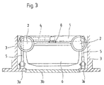
- the axle beam 1 is also via two trailing arms 4 and three wishbones 5 on the supporting vehicle frame 3 of the vehicle or on parts rigidly connected to the vehicle frame.
- the control arms 4 and 5 are used to track and camber one on the axle support 1 set and maintain the mounted wheel 6. For the better 1 the wheel 6 in the Normal position only indicated schematically.
- the axle support 1 is a double-walled hollow profile stiffened by cross struts educated.
- the axle support 1 is approximately in the shape of an H lying on the side, the bellows 2 on the top of the upper of the parallel legs 1a are arranged.
- the wheel 6 itself is over a stub axle 8 and one on the stub axle arranged braking device, not shown in the drawing, on the Axle beam 1 stored.
- the stub axle 8 inserted into the axle bracket 1 and welded to the axle bracket 1.
- the stub axle 8 is the stub axle 8 with the Bolted axle bracket 1.
- the articulation of the trailing arms 4 and the wishbones 5 is shown in the figures Fig. 1 and 3.
- the two trailing arms 4 are vertically one above the other on one side articulated on one side of the axle support 1. With the other end they are Trailing arm 4 mounted on rigid parts of the vehicle frame 3.
- the axle beam 1 in the longitudinal direction i.e. guided in the direction of travel so that the axle beam 1 is always parallel to Frame construction is guided.
- the bearing points are located 4a of the trailing arm 4 on the axle beam 1 as far apart as possible to the To minimize trailing arms 4 forces occurring during driving, and when and rebound of the wheel 6 as little displacement of the wheel 6 in Longitudinal effect.
- the wishbones 5 are on the one hand Axle beam 1 and the other articulated to parts 3a, which are rigid with the Vehicle frames are connected.
- the extend Wishbone 5 proceeding from the axle support 1 in the direction of that on the axle support 1 fixed stub axle 8 so far that it at least the width of the wheel 6 partially overlap to a linkage on a part 3a of the vehicle frame 3 to allow it to run along the long sides of the vehicle in vertical Direction down to the wheel hub.
- This laterally outside the wheels lying frame parts 3a of the vehicle frame 3 are in the embodiment rigid vertical supports, the design and arrangement of Fig. 2 and the 3 can be seen.
- the wheels 6 are between the frame parts or supports 3a at least in Area of each wheel 6 segments 3b can be used in segments Can be part of the vehicle outer frame thus formed.
- the suspension described is advantageously characterized in that the use of the stub axle 8 instead of the usual continuous Axis body the space between each other in the direction of travel opposite wheels 6 is available as storage space.
- the wheels 6 the width across wishbones 5 also allow the full Use of the storage space between the wheels 6 from the rear of the vehicle.
Abstract
Description
Die Erfindung betrifft eine Radaufhängung für Fahrzeuge, insbesondere Nutzfahrzeuganhänger, mit einem über mindestens eine Federung, insbesondere mindestens einen Federbalg, sowie mehrere Längs- und Querlenker an einem Fahrzeugrahmen gelagerten Achskörper, wobei Teile des Fahrzeugrahmens oder lenkeraufnehmende Stützen auf der Außenseite der Räder in vertikaler Richtung bis über die Räder herabgezogen ausgebildet sind.The invention relates to a wheel suspension for vehicles, in particular Commercial vehicle trailer, with one via at least one suspension, in particular at least one bellows, and several trailing arms and wishbones on one Vehicle frame mounted axle body, parts of the vehicle frame or handlebar supports on the outside of the wheels in a vertical direction until they are pulled down over the wheels.
Die gebräuchlichen, aus der Praxis allgemein bekannten Nutzfahrzeuganhänger weisen zwei parallele, sich zwischen den Rädern in Fahrtrichtung erstreckende Längsträger auf, an deren Unterseite die einzelnen Achskörper beispielsweise über Luftfederbälge gefedert sind. Der Aufbau des Nutzfahrzeuganhängers ist auf der Oberseite der Längsträger angeordnet. Zur Einstellung der Spur sowie des Sturzes der einzelnen Räder sind ferner nach innen zum Fahrzeugrahmen weisende und an diesem gelagerte Längs- und/oder Querlenker vorgesehen. Die Achskörper dieser bekannten Radaufhängungen für Nutzfahrzeuganhänger sind dabei im allgemeinen als durchgehende starre Achsstangen ausgebildet, an deren beiden Enden jeweils ein Rad gelagert ist.The usual commercial vehicle trailers that are well known in practice have two parallel, extending between the wheels in the direction of travel Longitudinal beams on the underside of which, for example, the individual axle beams are suspended over air bellows. The structure of the commercial vehicle trailer is on the top of the side members arranged. For setting the track and the Fall of the individual wheels are also inward to the vehicle frame pointing and mounted on this trailing and / or wishbone. The Axle bodies of these known wheel suspensions for commercial vehicle trailers are generally designed as a continuous rigid axle rods on their a wheel is supported at both ends.
Da die durchgehenden Achskörper die gesamte freie Breite des Anhängers überspannen, kann dieser zusätzliche Stauraum nur von der Seite zugänglich abseits der Radaufhängungen ausgebildet werden.Because the continuous axle beam the entire free width of the trailer span, this additional storage space can only be accessed from the side be trained away from the wheel suspensions.
Der Erfindung liegt die Aufgabe zugrunde, eine Radaufhängung der eingangs genannten Art so weiterzuentwickeln, daß auch der Raum zwischen den sich in Fahrtrichtung gesehen einander gegenüberliegenden Rädern als nutzbarer Stauraum zur Verfügung steht.The invention has for its object to develop a wheel suspension of the type mentioned so that the space between the opposite wheels seen in the direction of travel is available as usable storage space.
Die Lösung dieser Aufgabenstellung ist erfindungsgemäß dadurch gekennzeichnet, daß der Achskörper als Achsstummel zur Lagerung des Rades ausgebildet ist, der an einem sich am Fahrzeugrahmen abstützenden Achsträger festgelegt ist, und daß die Querlenker sich ausgehend von der einseitigen Lagerung an dem Achsträger über zumindest nahezu die Breite des jeweiligen Rades hinaus erstrecken und mit ihrem anderen Ende gelenkig an den äußeren Teilen des Fahrzeugrahmens angelenkt sind.The solution to this problem is characterized in that the axle body is designed as an axle stub for mounting the wheel, which is fixed to an axle support which is supported on the vehicle frame, and that the wishbones are based on the one-sided mounting on the axle support over at least almost the width extend of the respective wheel and are articulated at their other end to the outer parts of the vehicle frame.
Durch den Übergang vom durchgehenden starren Achskörper, an dem beidseitig jeweils ein Rad gelagert ist, hin zur Verwendung von Achsstummeln zur Lagerung nur eines Rades wird die Möglichkeit gegeben, den Raum zwischen den sich in Fahrtrichtung gesehen einander gegenüberliegenden Rädern zu nutzen. Neben der Verwendung der Achsstummel ist es zur Nutzbarmachung dieses Stauraums aber auch notwendig, die aus der Praxis bekannte Lagerung der nach innen zum Fahrzeugrahmen weisenden Querlenker zu modifizieren. Hierzu wird erfindungsgemäß erstmalig vorgeschlagen, daß die Querlenker die jeweiligen Räder in der Breite übergreifen, wodurch der Raum zwischen den sich einander gegenüberliegenden Rädern frei von sonstigen Aggregaten der Radaufhängung bleibt und somit als Laderaum zur Verfügung steht.Due to the transition from the continuous rigid axle body, on both sides one wheel is mounted to the use of stub axles for storage only one wheel is given the opportunity to move the space between itself Driving direction seen to use opposite wheels. Next the use of the stub axles makes this storage space usable but also necessary, the well-known storage from the inside to the Modify the wishbones of the vehicle frame. To do this proposed for the first time according to the invention that the wishbones each Wheels span across, creating space between each other opposite wheels free of other aggregates of the wheel suspension remains and is therefore available as a hold.
Gemäß einer bevorzugten Ausführungsform der Erfindung ist der Achsträger auf der Radinnenseite angeordnet und sind die Querlenker an dem seitlich herabgezogenen Teil des Fahrzeugrahmens gelagert. Diese Ausführungsform, bei der der Achsträger auf der Radinnenseite angeordnet ist, ist insbesondere bei der Montage und Demontage der Räder vorteilhaft. Selbstverständlich ist es aber auch möglich, den Achsträger auf der Radaußenseite anzuordnen, wobei dann die Querträger die Radbreite übergreifend an einem inneren Teil des Fahrzeugrahmens gelagert sind.According to a preferred embodiment of the invention, the axle support is on arranged on the inside of the wheel and the wishbones are on the side pulled down part of the vehicle frame stored. This embodiment, at the axle carrier is arranged on the inside of the wheel, is particularly in the Assembly and disassembly of the wheels advantageous. Of course it is too possible to arrange the axle on the outside of the wheel, then the Cross member across the wheel width on an inner part of the Vehicle frame are stored.
Um die Spurstabilität eines jeden Rades zu gewährleisten, ist jeder Achsträger über mindestens drei Querlenker am Fahrzeugrahmen gelagert, wobei mindestens zwei Querlenker die Radbreite an der einen Seite übergreifen und mindestens ein Querlenker die Radbreite an der gegenüberliegenden Seite dieses Rades übergreift. Durch die Verwendung von mindestens drei Querlenkern wird sichergestellt, daß das Rad bei auftretenden Querkräften nicht zu flattern beginnt und die Spurhaltung gewährt ist. Die Einstellung der Spur erfolgt durch Verstellen wenigstens eines Querlenkers.In order to ensure the tracking stability of each wheel, each axle carrier mounted on the vehicle frame via at least three wishbones, at least two wishbones overlap the wheel width on one side and at least one Wishbone the wheel width on the opposite side of this wheel spreads. By using at least three wishbones ensures that the wheel does not start to flutter when transverse forces occur and tracking is granted. The track is adjusted by adjusting it at least one wishbone.
Um die über die Längslenker aufzunehmenden Kräfte zu minimieren und das Maß der Längsverlagerung eines Rades beim Ein- und Ausfedern zu reduzieren, wird gemäß einer bevorzugten Ausführungsform der Erfindung vorgeschlagen, daß die Längslenker in Vertikalrichtung übereinander liegend möglichst weit voneinander beabstandet am Achsträger gelagert sind. Durch die Parallelführung des Achsträgers sowohl über die Längslenker als auch über die Querlenker ergibt sich insgesamt eine sehr stabile Radführung mit einer im wesentlichen nur vertikalen Bewegung des Rades beim Ein- und Ausfedern.To minimize the forces to be absorbed via the trailing arms and the dimension to reduce the longitudinal displacement of a wheel during compression and rebound proposed according to a preferred embodiment of the invention that the Trailing arms lying vertically one above the other as far apart as possible are spaced on the axle support. Through the parallel guidance of the Axle beam results from both the trailing arms and the wishbones overall a very stable wheel guide with an essentially vertical only Movement of the wheel during compression and rebound.
Der die Bremsvorrichtung und somit das Rad tragende Achsstummel ist gemäß einer ersten Ausführungsform der Erfindung mit dem Achsträger verschraubt, so daß zu Reparaturzwecken der Achsstummel mitsamt der Bremsvorrichtung einfach vom Achsträger getrennt werden kann.The stub axle carrying the braking device and thus the wheel is in accordance with a first embodiment of the invention screwed to the axle support, so that for repair purposes the stub axle together with the braking device can easily be separated from the axle beam.
Gemäß einer zweiten Ausführungsform der Erfindung wird vorgeschlagen, daß der Achsstummel mit dem Achsträger verschweißt ist.According to a second embodiment of the invention it is proposed that the Axle stub is welded to the axle support.
Weiterhin wird mit der Erfindung vorgeschlagen, daß zur schnellen Tilgung von Schwingungen zwischen dem Achsträger und dem Fahrzeugrahmen mindestens ein Stoßdämpfer angeordnet ist.Furthermore, the invention proposes that for the rapid repayment of Vibrations between the axle beam and the vehicle frame at least a shock absorber is arranged.
Schließlich wird mit der Erfindung vorgeschlagen, daß der Achsträger als in Seitenansicht H-förmiges, doppelwandiges und über mehrere Querstreben versteiftes Hohlprofil ausgebildet ist. Diese Ausbildung des Achsträgers ist besonders gut dazu geeignet, die beim Fahr- und Bremsvorgang auftretenden Kräfte aufzunehmen und über die Längs- und Querlenker auf den Fahrzeugrahmen abzuleiten. Finally, the invention proposes that the axle support as in Side view H-shaped, double-walled and over several cross struts stiffened hollow profile is formed. This training of the axle carrier is particularly well suited to those that occur during driving and braking Take up forces and on the trailing and wishbones on the Derive vehicle frame.
Weitere Merkmale und Vorteile der Erfindung ergeben sich aus der nachfolgenden Beschreibung der zugehörigen Zeichnung, in der ein Ausführungsbeispiel einer erfindungsgemäßen Radaufhängung beispielhaft schematisch dargestellt ist. In der Zeichnung zeigt:
- Fig. 1
- eine Seitenansicht einer erfindungsgemäßen Radaufhängung mit nur schematisch angedeutetem Rad;
- Fig. 2
- eine schematische Vorderansicht der Radaufhängung gemäß Fig. 1 und
- Fig. 3
- eine schematische Ansicht von oben auf die Radaufhängung gemäß Fig.1 und 2.
- Fig. 1
- a side view of a wheel suspension according to the invention with only a schematically indicated wheel;
- Fig. 2
- is a schematic front view of the wheel suspension according to FIGS. 1 and
- Fig. 3
- a schematic view from above of the wheel suspension according to Fig.1 and 2.
Die in Fig. 1 dargestellte Radaufhängung besteht im wesentlichen aus einem
Achsträger 1, der im dargestellten Ausführungsbeispiel über zwei Luftfederbälge 2
als Federungselemente an den oberhalb angeordneten Teilen eines
Fahrzeugrahmens 3 gelagert ist. Der Achsträger 1 ist ferner über zwei Längslenker
4 und drei Querlenker 5 am tragenden Fahrzeugrahmen 3 des Fahrzeugs bzw. an
mit dem Fahrzeugrahmen starr verbundenen Teilen gelagert. Die Querlenker 4
und 5 dienen dazu, die Spur und den Radsturz eines an dem Achsträger 1
gelagerten Rades 6 einzustellen und beizubehalten. Aus Gründen der besseren
Übersichtlichkeit wurde bei der Darstellung gemäß Fig. 1 das Rad 6 in der
Normalstellung nur schematisch angedeutet.The wheel suspension shown in Fig. 1 consists essentially of a
Neben der dargestellten Ausbildung der Federung zwischen dem Achsträger 1 und
dem Fahrzeugrahmen 3 als Luftfederbälge 2 ist es selbstverständlich auch
möglich, z. B. Blattfedern zu verwenden. Um möglichst schnell auftretende
Schwingungen zu tilgen, ist zwischen dem Achsträger 1 und dem
Fahrzeugrahmen 3 zusätzlich ein Stoßdämpfer 7 angeordnet.In addition to the illustrated design of the suspension between the
Der Achsträger 1 ist als doppelwandiges, durch Querstreben versteiftes Hohlprofil
ausgebildet. Beim dargestellten Ausführungsbeispiel ist der Achsträger 1 in etwa in
der Form eines auf der Seite liegenden H ausgebildet, wobei die Federbälge 2 auf
der Oberseite des oberen der parallel zueinander verlaufenden Schenkel 1a
angeordnet sind. The
Das Rad 6 selbst ist über einen Achsstummel 8 und eine auf dem Achsstummel
angeordnete, in der Zeichnung nicht dargestellte Bremsvorrichtung an dem
Achsträger 1 gelagert. Bei der dargestellten Ausführungsform ist der Achsstummel
8 in den Achsträger 1 eingesteckt und mit dem Achsträger 1 verschweißt. Gemäß
einer anderen, nicht dargestellten Ausführungsform ist der Achsstummel 8 mit dem
Achsträger 1 verschraubt.The
Die Anlenkung der Längslenker 4 sowie der Querlenker 5 ist den Abbildungen Fig.
1 und 3 zu entnehmen. Die zwei Längslenker 4 sind einseitig vertikal übereinander
an einer Seite des Achsträgers 1 angelenkt. Mit dem anderen Ende sind die
Längslenker 4 an starren Teilen des Fahrzeugrahmens 3 gelagert. Durch die
parallele Anordnung der Längslenker 4 wird der Achsträger 1 in Längsrichtung,
d.h. in Fahrtrichtung so geführt, daß der Achsträger 1 stets parallel zur
Rahmenkonstruktion geführt ist. Wie aus Fig. 1 ersichtlich, liegen die Lagerpunkte
4a der Längslenker 4 am Achsträger 1 möglichst weit auseinander, um die an den
Längslenkern 4 im Fahrbetrieb auftretenden Kräfte zu minimieren, und beim Ein-
und Ausfedern des Rades 6 eine möglichst geringe Verlagerung des Rades 6 in
Längsrichtung zu bewirken.The articulation of the
Ebenso wie die Längslenker 4, sind auch die Querlenker 5 zum einen am
Achsträger 1 und zum anderen an Teilen 3a angelenkt, die starr mit dem
Fahrzeugrahmen verbunden sind. Wie aus Fig. 3 ersichtlich, erstrecken sich die
Querlenker 5 ausgehend vom Achsträger 1 in Richtung des am Achsträger 1
festgelegten Achsstummel 8 so weit, daß sie die Breite des Rades 6 zumindest
teilweise übergreifen, um eine Anlenkung an einem Teil 3a des Fahrzeugrahmens
3 zu ermöglichen, der sich entlang der Längsseiten des Fahrzeugs in vertikaler
Richtung herab bis über die Radnabe erstreckt. Diese seitlich außerhalb der Räder
liegenden Rahmenteile 3a des Fahrzeugrahmens 3 sind beim Ausführungsbeispiel
starre vertikale Stützen, deren Gestaltung und Anordnung der Fig. 2 sowie der
Draufsicht gemäß Fig. 3 zu entnehmen ist. Zu Montage- und Demontagezwecken
der Räder 6 sind zwischen den Rahmenteilen bzw. Stützen 3a zumindest im
Bereich eines jeden Rades 6 segmentweise Abdeckungen 3b einsetzbar, die
Bestandteil des so gebildeten Fahrzeug-Außenrahmens sein können. Just like the
Die beschriebene Radaufhängung zeichnet sich vorteilhaft dadurch aus, daß durch
die Verwendung der Achsstummel 8 an Stelle der üblichen durchgehenden
Achskörper der Raum zwischen den in Fahrtrichtung einander
gegenüberliegenden Rädern 6 als Stauraum zur Verfügung steht. Die die Räder 6
der Breite nach übergreifenden Querlenker 5 ermöglichen ebenso die volle
Nutzung des zwischen den Rädern 6 vorhandenen Stauraums von der Rückseite
des Fahrzeugs her. The suspension described is advantageously characterized in that
the use of the
- 11
- AchsträgerAxle support
- 1a1a
- Schenkelleg
- 22nd
- LuftfederbalgAir bag
- 33rd
- FahrzeugrahmenVehicle frame
- 3a3a
- äußeres Teil des Fahrzeugrahmens, vertikale Stützeouter part of the vehicle frame, vertical support
- 3b3b
- Abdeckungcover
- 44th
- LängslenkerTrailing link
- 4a4a
- LagerpunktBearing point
- 55
- QuerlenkerWishbones
- 66
- Rad (in Normalposition)Wheel (in normal position)
- 77
- StoßdämpferShock absorber
- 88th
- AchsstummelStub axle
Claims (10)
dadurch gekennzeichnet,
daß der Achskörper als Achsstummel (8) zur Lagerung des Rades (6) ausgebildet ist, der an einem sich am Fahrzeugrahmen (3) abstützenden Achsträger (1) festgelegt ist, und daß die Querlenker (5) sich ausgehend von der einseitigen Anlenkung an dem Achsträger (1) über zumindest nahezu die Breite des Rades (6) hinaus erstrecken und mit ihren anderen Enden an den äußeren Teilen (3a) des Fahrzeugrahmens (3) angelenkt sind.Wheel suspension for vehicles, in particular commercial vehicle trailers, with an axle body mounted on at least one suspension, in particular at least one bellows (2), and a plurality of longitudinal and transverse links (4, 5) on a vehicle frame (3), parts of the vehicle frame or handlebar-receiving supports the outside of the wheels (6) are designed in a vertical direction until they are pulled down over the wheels (6),
characterized by
that the axle body is designed as an axle stub (8) for mounting the wheel (6) which is fixed to an axle support (1) which is supported on the vehicle frame (3), and that the wishbones (5) are based on the one-sided linkage on the Axle carriers (1) extend at least almost the width of the wheel (6) and are hinged at their other ends to the outer parts (3a) of the vehicle frame (3).
Applications Claiming Priority (2)
| Application Number | Priority Date | Filing Date | Title |
|---|---|---|---|
| DE2000104227 DE10004227A1 (en) | 2000-02-01 | 2000-02-01 | Wheel suspension for vehicles, in particular commercial vehicle trailers |
| DE10004227 | 2000-02-01 |
Publications (2)
| Publication Number | Publication Date |
|---|---|
| EP1122101A2 true EP1122101A2 (en) | 2001-08-08 |
| EP1122101A3 EP1122101A3 (en) | 2003-11-19 |
Family
ID=7629373
Family Applications (1)
| Application Number | Title | Priority Date | Filing Date |
|---|---|---|---|
| EP01101853A Withdrawn EP1122101A3 (en) | 2000-02-01 | 2001-01-26 | Wheel suspension for vehicles, particularly for utility vehicle trailers |
Country Status (2)
| Country | Link |
|---|---|
| EP (1) | EP1122101A3 (en) |
| DE (1) | DE10004227A1 (en) |
Cited By (5)
| Publication number | Priority date | Publication date | Assignee | Title |
|---|---|---|---|---|
| WO2004076263A1 (en) * | 2003-02-27 | 2004-09-10 | Tg Consulting, Besloten Vennootschap Met Beperkte Aansprakelijkheid | Semi-trailer chassis and wheel suspension |
| EP1127749A3 (en) * | 2000-02-24 | 2005-12-14 | SCHIMMELPFENNIG, Karl-Heinz | Protection frame for road vehicles |
| FR2914586A1 (en) * | 2007-04-03 | 2008-10-10 | Renault Sas | MULTI-ARM REAR TRAIN FOR MOTOR VEHICLE |
| NL2013397B1 (en) * | 2014-09-01 | 2016-09-26 | Broshuis B V | Independent wheel suspension with air suspension for a trailer and trailers equipped with it. |
| EP3978279A1 (en) * | 2020-10-01 | 2022-04-06 | Onomotion GmbH | Wagons for transporting people and/or goods |
Family Cites Families (7)
| Publication number | Priority date | Publication date | Assignee | Title |
|---|---|---|---|---|
| US2330482A (en) * | 1941-03-26 | 1943-09-28 | Twin Coach Co | Vehicle spring suspension |
| US2466832A (en) * | 1946-04-20 | 1949-04-12 | Marmon Herrington Co Inc | Wheel suspension |
| US3511493A (en) * | 1967-10-23 | 1970-05-12 | Gen Motors Corp | Camber change and roll steer inducing leaf spring suspension |
| US4610461A (en) * | 1985-06-17 | 1986-09-09 | Matthew Guzzetta | Steering system for elimination of bump steering in independent wheel suspension systems |
| IT1255575B (en) * | 1992-07-10 | 1995-11-09 | TRANSVERSAL MINIMUM SIZE SUSPENSION, IN PARTICULAR FOR LOW-FLOOR VEHICLES. | |
| DE4336672A1 (en) * | 1993-10-27 | 1995-05-04 | Zahnradfabrik Friedrichshafen | Independent suspension |
| DE19544276B4 (en) * | 1994-12-06 | 2005-11-24 | Volkswagen Ag | Independent suspension for the steered wheels of a motor vehicle front axle |
-
2000
- 2000-02-01 DE DE2000104227 patent/DE10004227A1/en not_active Ceased
-
2001
- 2001-01-26 EP EP01101853A patent/EP1122101A3/en not_active Withdrawn
Non-Patent Citations (1)
| Title |
|---|
| None |
Cited By (9)
| Publication number | Priority date | Publication date | Assignee | Title |
|---|---|---|---|---|
| EP1127749A3 (en) * | 2000-02-24 | 2005-12-14 | SCHIMMELPFENNIG, Karl-Heinz | Protection frame for road vehicles |
| WO2004076263A1 (en) * | 2003-02-27 | 2004-09-10 | Tg Consulting, Besloten Vennootschap Met Beperkte Aansprakelijkheid | Semi-trailer chassis and wheel suspension |
| BE1015391A3 (en) * | 2003-02-27 | 2005-03-01 | Tg Consulting Bv Met Beperkte | Improved trailer. |
| CN100431899C (en) * | 2003-02-27 | 2008-11-12 | Tg咨询有限责任公司 | Semi-trailer chassis and wheel suspension |
| FR2914586A1 (en) * | 2007-04-03 | 2008-10-10 | Renault Sas | MULTI-ARM REAR TRAIN FOR MOTOR VEHICLE |
| WO2008129211A1 (en) * | 2007-04-03 | 2008-10-30 | Renault S.A.S | Multiple-arm rear axle for an automobile |
| NL2013397B1 (en) * | 2014-09-01 | 2016-09-26 | Broshuis B V | Independent wheel suspension with air suspension for a trailer and trailers equipped with it. |
| EP3978279A1 (en) * | 2020-10-01 | 2022-04-06 | Onomotion GmbH | Wagons for transporting people and/or goods |
| US11541709B2 (en) | 2020-10-01 | 2023-01-03 | Onomotion Gmbh | Vehicle for the transport of persons and/or goods |
Also Published As
| Publication number | Publication date |
|---|---|
| EP1122101A3 (en) | 2003-11-19 |
| DE10004227A1 (en) | 2001-08-02 |
Similar Documents
| Publication | Publication Date | Title |
|---|---|---|
| DE1605826C3 (en) | Bogie for railway wagons with at least two wheelsets | |
| EP0290587B1 (en) | Independent vehicle wheel suspension, especially suitable for a bus | |
| WO2003008212A1 (en) | Rear axle of a passenger vehicle with five individual links | |
| DE1630839B2 (en) | AXLE SUSPENSION FOR MOTOR VEHICLES | |
| EP2435263B1 (en) | Independent vehicle suspension | |
| EP0352541A1 (en) | Resilient axle suspension for motor vehicles, in particular for utility vehicles | |
| DE1086138B (en) | Independent suspension for trucks | |
| DE19622954C2 (en) | Wheel suspension for a motor vehicle | |
| DE19533263A1 (en) | Bogie for rail vehicles | |
| DE19756066C2 (en) | Vehicle axle with at least one, at least one lever, wheel-carrying handlebar per vehicle wheel | |
| DE696526C (en) | Chassis for motor vehicles and motor vehicle trailers with torsion spring bars in hollow cross members | |
| EP1122101A2 (en) | Wheel suspension for vehicles, particularly for utility vehicle trailers | |
| DE10011417B4 (en) | Independent wheel suspension with wheel-guiding semi-trailing arms | |
| DE2439365B2 (en) | Wheel suspension for motor vehicles, in particular for passenger cars | |
| DE3338467A1 (en) | Rear wheel suspension | |
| EP1277603A2 (en) | Multi link independent wheel suspension, in particular suspension of a steerable front wheel of a motor vehicle | |
| DE2415708A1 (en) | Vertically stabilised rigid rear axle - is braced by trailing struts and by diagonal struts leading to strong chassis points | |
| DE3124837C2 (en) | Transport vehicle, in particular trailer vehicle | |
| DE4407398C2 (en) | Axle lift for air-sprung vehicle axles | |
| EP0225851B1 (en) | Wheel suspension device for a cross-country vehicle moving slowly, particularly for a horse-drawn cart | |
| DE900059C (en) | Suspension for vehicles | |
| EP0930182A2 (en) | Rear axle of a motor vehicle with at least two consecutively arranged transverse leaf springs | |
| DE7927609U1 (en) | Trailer with a torsion crank axle | |
| DE2502560A1 (en) | Independent front wheel suspension - has wheel guiding suspension legs and rigid trailing link | |
| DE2630445A1 (en) | REAR CHASSIS FOR MOTOR VEHICLES |
Legal Events
| Date | Code | Title | Description |
|---|---|---|---|
| PUAI | Public reference made under article 153(3) epc to a published international application that has entered the european phase |
Free format text: ORIGINAL CODE: 0009012 |
|
| AK | Designated contracting states |
Kind code of ref document: A2 Designated state(s): AT BE CH CY DE DK ES FI FR GB GR IE IT LI LU MC NL PT SE TR |
|
| AX | Request for extension of the european patent |
Free format text: AL;LT;LV;MK;RO;SI |
|
| PUAL | Search report despatched |
Free format text: ORIGINAL CODE: 0009013 |
|
| AK | Designated contracting states |
Kind code of ref document: A3 Designated state(s): AT BE CH CY DE DK ES FI FR GB GR IE IT LI LU MC NL PT SE TR |
|
| AX | Request for extension of the european patent |
Extension state: AL LT LV MK RO SI |
|
| RIC1 | Information provided on ipc code assigned before grant |
Ipc: 7B 60B 35/02 B Ipc: 7B 62D 17/00 B Ipc: 7B 60G 3/20 B Ipc: 7B 60G 11/28 A |
|
| AKX | Designation fees paid | ||
| REG | Reference to a national code |
Ref country code: DE Ref legal event code: 8566 |
|
| STAA | Information on the status of an ep patent application or granted ep patent |
Free format text: STATUS: THE APPLICATION IS DEEMED TO BE WITHDRAWN |
|
| 18D | Application deemed to be withdrawn |
Effective date: 20040521 |