EP1121882A2 - Automatic unit for preparing espresso coffee - Google Patents
Automatic unit for preparing espresso coffee Download PDFInfo
- Publication number
- EP1121882A2 EP1121882A2 EP00204488A EP00204488A EP1121882A2 EP 1121882 A2 EP1121882 A2 EP 1121882A2 EP 00204488 A EP00204488 A EP 00204488A EP 00204488 A EP00204488 A EP 00204488A EP 1121882 A2 EP1121882 A2 EP 1121882A2
- Authority
- EP
- European Patent Office
- Prior art keywords
- hollow body
- unit
- delivery means
- hot water
- compartment
- Prior art date
- Legal status (The legal status is an assumption and is not a legal conclusion. Google has not performed a legal analysis and makes no representation as to the accuracy of the status listed.)
- Granted
Links
Images



Classifications
-
- A—HUMAN NECESSITIES
- A47—FURNITURE; DOMESTIC ARTICLES OR APPLIANCES; COFFEE MILLS; SPICE MILLS; SUCTION CLEANERS IN GENERAL
- A47J—KITCHEN EQUIPMENT; COFFEE MILLS; SPICE MILLS; APPARATUS FOR MAKING BEVERAGES
- A47J31/00—Apparatus for making beverages
- A47J31/24—Coffee-making apparatus in which hot water is passed through the filter under pressure, i.e. in which the coffee grounds are extracted under pressure
- A47J31/34—Coffee-making apparatus in which hot water is passed through the filter under pressure, i.e. in which the coffee grounds are extracted under pressure with hot water under liquid pressure
- A47J31/36—Coffee-making apparatus in which hot water is passed through the filter under pressure, i.e. in which the coffee grounds are extracted under pressure with hot water under liquid pressure with mechanical pressure-producing means
- A47J31/3604—Coffee-making apparatus in which hot water is passed through the filter under pressure, i.e. in which the coffee grounds are extracted under pressure with hot water under liquid pressure with mechanical pressure-producing means with a mechanism arranged to move the brewing chamber between loading, infusing and ejecting stations
- A47J31/3623—Cartridges being employed
- A47J31/3633—Means to perform transfer from a loading position to an infusing position
-
- A—HUMAN NECESSITIES
- A47—FURNITURE; DOMESTIC ARTICLES OR APPLIANCES; COFFEE MILLS; SPICE MILLS; SUCTION CLEANERS IN GENERAL
- A47J—KITCHEN EQUIPMENT; COFFEE MILLS; SPICE MILLS; APPARATUS FOR MAKING BEVERAGES
- A47J31/00—Apparatus for making beverages
- A47J31/24—Coffee-making apparatus in which hot water is passed through the filter under pressure, i.e. in which the coffee grounds are extracted under pressure
- A47J31/34—Coffee-making apparatus in which hot water is passed through the filter under pressure, i.e. in which the coffee grounds are extracted under pressure with hot water under liquid pressure
- A47J31/36—Coffee-making apparatus in which hot water is passed through the filter under pressure, i.e. in which the coffee grounds are extracted under pressure with hot water under liquid pressure with mechanical pressure-producing means
Definitions
- This invention relates to a completely automatic unit for preparing espresso coffee, in which the various mutually moving parts are operated by the pressurized water delivered by the service pump, further electrical or pneumatic controls being absent.
- the known art provides automatic espresso coffee dispensing units comprising mutually moving parts driven by electrical actuators controlled by sophisticated means, to ensure that the coffee powder is subjected to the correct pressure necessary to obtain a drink having the required quality.
- Dispensing units of known type are complicated and costly, are difficult and onerous to maintain, and have to be installed by specialised personnel possessing the necessary equipment.
- the main object of the invention is to provide an espresso coffee dispensing unit of simple and economical construction, installation and assembly, and which can be used without difference either in automatic machines for professional use, or in machines intended for domestic use.
- a further object of the invention is to provide a coffee dispensing unit of the aforesaid characteristics, which can be used with loose ground coffee, or with sachets or capsules pre-filled with ground coffee.
- a particular object of the invention is to provide a dispensing unit able to use those pre-filled sachets of coffee powder of the capsule type comprising a semi-rigid cup with a filtering base and top, and provided with a support collar.
- an automatic espresso coffee dispensing unit comprising hot water delivery means and, for containing coffee powder, a compartment to be moved into sealed relationship against said delivery means, said compartment being in the form of a cylindrical jacket rigid with a movable hollow body which is sealedly mounted on a fixed hollow body to create a variable volume chamber connected to the operating pump of the dispenser.
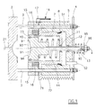
- Figure 1 is a horizontal section through a first embodiment of the invention in its rest position.
- Figure 2 shows this latter in its first operative phase.
- Figure 3 shows this latter in its second operative phase.
- Figure 4 is a section on the line IV-IV of Figure 2.
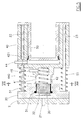
- Figure 5 is a horizontal section through a second embodiment of the invention in its rest position.
- Figure 6 shows this latter in an operative phase.
- Figure 7 is a section on the line VII-VII of Figure 5.
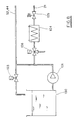
- Figure 8 shows a possible hydraulic circuit for the device.
- the dispensing unit 1 shown in Figures 1 to 4 comprises a normal hot water delivery means 2 from which two cylindrical rods 3 extend towards the right to support a fixed plate 4.
- the rods 3 carry mounted thereon a fixed hollow body 5 provided with a cylindrical inner cavity 51 in which a movable hollow body or first hollow piston 7 slides in sealed relationship, or a first hollow piston 7 with interposed gasket 8.
- the first hollow piston 7 presents at one end a flange 71 which is also mounted on the rods 3 and is connected to the plate 4 by a first spring 72 of tension type which maintains it resting on the body 5.
- the first hollow piston or movable hollow body 7 carries upperly fixed thereto a cylindrical jacket 73 within which a second piston 9 slides by way of an interposed gasket 10.
- the second piston 9 presents an axial conduit 91 which extends to the right into a tube 92 which sealedly passes through the base of the first hollow piston 7 and the base of the cylindrical cavity of the body 5 to reach beyond the plate 4; the gaskets 11 and 12 provide the seal.
- the second piston 9 presents at its left end a depression 93, from the centre of which there extends said axial conduit 91, and which is closed by a perforated plate 94.
- a disc 95 which acts as a support for a second spring 13 of compression type acting between said disc and the base of the body 5.
- the disc 95 is slidable axially on the tube 91, which has its end externally threaded for a short distance, and is maintained in position by a nut 96 screwed onto the tube 91.
- the springs 13 and 14 are compressed to a greater or lesser extent by screwing down the nut 96 to a greater or lesser degree.
- a third spring 14 of compression type is positioned between the base of the second piston 9 and the base of the first hollow piston, to maintain the end of said the second piston at the level of the cylindrical jacket 73 as shown in Figure 1.
- the two rings 3 carry axially slidable thereon a hollow body 15 which has two cavities receiving a pair of fourth springs 16 of compression type, and has an axial dimensional such that its left end is flush with the cylindrical jacket 73.
- An elastic pawl 17 is securely fixed to the flange 71 of the first hollow pistons 7, and is inserted elastically into a seat provided in the annular body 15.
- the annular body 15 upperly presents a radial conduit 15 well visible in Figure 4.
- the elastic pawl 17 When it is desired to dispense espresso coffee, the elastic pawl 17 is pressed with one finger in the direction of the arrow 18, so releasing the annular body 15 from the flange 71 of the first hollow piston 7.
- the annular body is moved into contact with the hot water delivery means 2, so creating a cylindrical compartment 152 into which coffee powder is fed via the conduit 151.
- the service pump and the two-way valve 103 are operated to feed pressurized water below the first hollow piston 7, this latter being displaced until the cylindrical jacket 73 makes sealed contact with the wall of the distributor 2 and the flange 71 makes contact with the annular body 15 to cause the pawl 17 to snap-operate and hook onto the annular body, as shown in Figure 3.
- the second piston 9 withdraws against the action of the third spring 14 to maintain the coffee conveniently pressed.
- the unit is hence ready to dispense the coffee, which is achieved by opening a timed valve 106 ( Figure 8), to deliver hot water.
- valve 106 When delivery is complete the valve 106 returns to its initial position, to discharge the hot water lying within the circuit between it and the spring-loaded valve 105, then the valve 103 is again operated to return it into its initial position, and discharge the water acting against the first hollow piston, so enabling the first spring 72 to reposition this latter and the annular body coupled to it as shown in Figure 1.
- FIGS. 5 to 7 show the hot water delivery means 2 with which there is associated a plate 20 provided with a central groove 21 the edges of which present two parallel projecting ribs 22 for supporting and guiding the upper rim 31 of a capsule 30 containing ground coffee.
- Said ribs are interrupted at the position in which the capsule is axially aligned with a cylindrical jacket 41 which projects from a body 40 in the shape of an inverted cup corresponding to the hollow body 5 of Figure 1 slightly modified.
- This latter is sealedly mounted, via a gasket 42, on the outside of a fixed piston 50 which is joined to the plate 20 at a precise distance therefrom by two rods 23 on which the cup-shaped body 40 is slidingly mounted.
- the cylindrical jacket 41 contains a spring 42 which when in its rest position reaches flush with the outer edge of the jacket.
- the interior of the cup-shaped body communicates with the pump 101 via a conduit 44.
- the interior of the cylindrical jacket communicates with the outside via the conduit 46 through which the coffee is dispensed into a cup.
- the second embodiment of the invention operates in the following manner.
- a capsule 30 is made to slide from the outside by falling along the ribs 22 until it lies coaxial with the jacket 41.
- Operation of the service pump 101 and valve 103 causes the cup-shaped body 40 to advance until the edge 440sealedly rests against the edge of the perforated base 32 of the capsule 30, pressing it in its turn sealedly against the plate 20, to attain the configuration of Figure 6.
- the retractable pin 23 is withdrawn electromagnetically when the jacket 41 supports the capsule.
- Advancement of the body 40 simultaneously causes compression of the spring 40 against the perforated base 32 of the capsule 30.
- hot water After passing through the heater 104, hot water is delivered by means of the pump 101 and valve 106 for a predetermined time, it filtering through the capsule 30 to collect in the form of espresso coffee at the exit of the conduit 46.
Landscapes
- Engineering & Computer Science (AREA)
- Mechanical Engineering (AREA)
- Food Science & Technology (AREA)
- Apparatus For Making Beverages (AREA)
- Tea And Coffee (AREA)
- Eye Examination Apparatus (AREA)
Abstract
Description
Claims (11)
- An automatic espresso coffee dispensing unit comprising hot water delivery means (2) and, for containing coffee powder or a capsule, a compartment (47, 152) to be moved into sealed relationship against said delivery means, characterised in that said compartment is in the form of a cylindrical jacket (73, 41) rigid with a movable hollow body (7, 40) which is sealedly mounted on a fixed hollow body (5, 50) to create a variable volume chamber connected via a two- or three-way valve alternately to a pressurized water source and to discharge.
- A unit as claimed in claim 1, characterised in that the base of the compartment (47) containing coffee powder consists of a perforated wall movable elastically in opposition to a spring.
- A unit as claimed in claim 1, characterised in that the base of the compartment (152) containing coffee powder consists of a piston (9) presenting, for exit of the infused liquid, an axial conduit (91) extending into a tube (92) which sealedly passes through the base of the movable hollow body and the base of the fixed hollow body.
- A unit as claimed in claim 1, characterised in that said movable hollow body (7, 40) is slidable on two rods (3, 23) which connect the fixed hollow body to the hot water delivery means, and is maintained in contact with the fixed hollow body by elastic means (72, 51).
- A unit as claimed in claim 1, characterised in that between the movable hollow body and the hot water delivery means there is provided an annular body (15) which is mounted on the outside of said jacket (73) and can assume a withdrawn position in contact with said movable hollow body and an advanced position in contact with said delivery means.
- A unit as claimed in claim 5, characterised in that between said annular body (15) and said movable hollow body (7) there are provided elastic means (16) arranged to advance the annular body into contact with the delivery means, and an elastic pawl (17) arranged to maintain the annular body in contact with the hollow body.
- A unit as claimed in claim 5, characterised in that said annular body (15) presents a substantially radial conduit (151) through which loose coffee powder is introduced.
- A unit as claimed in claim 5, characterised in that said annular body (15) is slidingly mounted on the rods (3) which connect the hot water delivery means (2) to the fixed hollow body (5).
- A unit as claimed in claim 1, characterised in that between the hot water delivery means (2) and the movable hollow body (40) there is provided a plate (20) possessing a channel (21) with internally projecting ribs (22) for guiding the rim of a cup capsule (30) containing coffee powder.
- A unit as claimed in claim 8, characterised in that said plate (20) is securely fixed to the hot water delivery means (2).
- A unit as claimed in claim 8, characterised in that said support ribs (22) are interrupted in that portion overlying said jacket (41).
Applications Claiming Priority (2)
| Application Number | Priority Date | Filing Date | Title |
|---|---|---|---|
| IT2000BO000053A IT1321007B1 (en) | 2000-02-07 | 2000-02-07 | AUTOMATIC GROUP FOR THE EXPLOITATION OF COFFEE AND OTHER BEVERAGES WITH HYDRAULIC DRIVE |
| ITBO000053 | 2000-02-07 |
Publications (3)
| Publication Number | Publication Date |
|---|---|
| EP1121882A2 true EP1121882A2 (en) | 2001-08-08 |
| EP1121882A3 EP1121882A3 (en) | 2001-09-12 |
| EP1121882B1 EP1121882B1 (en) | 2003-05-21 |
Family
ID=11438145
Family Applications (1)
| Application Number | Title | Priority Date | Filing Date |
|---|---|---|---|
| EP00204488A Expired - Lifetime EP1121882B1 (en) | 2000-02-07 | 2000-12-13 | Automatic unit for preparing espresso coffee |
Country Status (7)
| Country | Link |
|---|---|
| US (1) | US6431055B2 (en) |
| EP (1) | EP1121882B1 (en) |
| AT (1) | ATE240671T1 (en) |
| AU (1) | AU782522B2 (en) |
| CA (1) | CA2334422C (en) |
| DE (1) | DE60002820T2 (en) |
| IT (1) | IT1321007B1 (en) |
Cited By (13)
| Publication number | Priority date | Publication date | Assignee | Title |
|---|---|---|---|---|
| GB2371213A (en) * | 2001-09-10 | 2002-07-24 | Tsann Kuen Usa Inc | Coffee feed and discharge in an electric coffee maker |
| GB2371212A (en) * | 2001-10-05 | 2002-07-24 | Tsann Kuen Usa Inc | Coffee feed and discharge in an electric coffee machine |
| WO2004049878A1 (en) * | 2002-12-02 | 2004-06-17 | Necta Vending Solutions S.P.A. | Mechanically and hydrodynamically operated brewing unit |
| EP1444932A1 (en) * | 2003-02-07 | 2004-08-11 | Nestec S.A. | Linear extraction unit for the preparation under pressure of a drink from a cartridge |
| EP1532904A1 (en) * | 2003-11-20 | 2005-05-25 | Steiner AG Weggis | Coffee machine |
| US8425963B2 (en) | 2003-07-10 | 2013-04-23 | Nestec S.A. | Method for extracting a beverage from a capsule |
| US9119503B2 (en) | 2007-10-04 | 2015-09-01 | Nestec S.A. | Beverage brewing unit |
| US9398829B2 (en) | 2007-10-04 | 2016-07-26 | Nestec S.A. | Integrated heater for a beverage preparation device |
| US9439533B2 (en) | 2007-10-04 | 2016-09-13 | Nestec S.A. | Heating device with an integrated thermoblock for a beverage preparation machine |
| CN106163348A (en) * | 2014-04-08 | 2016-11-23 | 雀巢产品技术援助有限公司 | Utilize the series connection many size capsules of actuation process |
| ITUB20152087A1 (en) * | 2015-07-10 | 2017-01-10 | Living Tech Soc A Responsabilita Limitata Semplificata | COFFEE BREWING APPARATUS |
| CN108888116A (en) * | 2018-07-17 | 2018-11-27 | 无锡鼎加弘思饮品科技有限公司 | A kind of capsule beverage Vending Machine of vertical and lateral storing |
| WO2025034103A1 (en) | 2023-08-09 | 2025-02-13 | Bravilor Bonamat B.V. | Brewer for a coffee machine |
Families Citing this family (43)
| Publication number | Priority date | Publication date | Assignee | Title |
|---|---|---|---|---|
| ES2182390T3 (en) * | 1998-12-24 | 2003-03-01 | Cie Mediterraneenne Des Cafes | CHAMBER OF EXTRACTION FOR AUTOMATIC MACHINE FOR THE PREPARATION OF HOT DRINKS. |
| IT1320486B1 (en) * | 2000-05-31 | 2003-12-10 | Rancilio Macchine Per Caffe Sp | COFFEE MACHINE'. |
| ITTO20040476A1 (en) * | 2004-07-09 | 2004-10-09 | Sgl Italia Srl | METHOD FOR PREPARING A DRINK FROM POWDERED MATERIAL PLACED IN A SEALED CAPSULE. |
| US7032504B2 (en) * | 2004-09-16 | 2006-04-25 | Pao Chen Lee | Filtering device for espresso maker |
| EP1940268B1 (en) | 2005-04-11 | 2011-11-09 | Starbucks Corporation | Machine for brewing a beverage such as coffee and related method |
| WO2007027206A2 (en) | 2005-04-11 | 2007-03-08 | Coffee Equipment Company | Machine for brewing a beverage such as coffee and related method |
| ITVE20050061A1 (en) * | 2005-12-13 | 2007-06-14 | Macap S R L | MANUAL PRESS |
| DE502007000181D1 (en) * | 2006-04-25 | 2008-12-04 | Imel Ag | Apparatus and method for the preparation of hot drinks by brewing a particulate, extractable by water substance |
| ITFI20070028A1 (en) * | 2007-02-07 | 2008-08-08 | Saeco Ipr Ltd | INFUSION DEVICE FOR THE PREPARATION OF DRINKS FROM SINGLE-DOSE CAPSULES WITH A CAPSULES CENTERING DEVICE. |
| FR2916336A1 (en) * | 2007-05-21 | 2008-11-28 | Cie Mediterraneenne Des Cafes | INFUSION BEVERAGE PRODUCTION SYSTEM |
| CN100544647C (en) * | 2007-06-15 | 2009-09-30 | 宁波三A集团电器有限公司 | Automatic shedding mechanism for coffee pods in coffee machines |
| JP2011518015A (en) | 2008-04-22 | 2011-06-23 | ネステク ソシエテ アノニム | Module assembly for beverage production equipment |
| WO2010015427A1 (en) | 2008-08-08 | 2010-02-11 | Nestec S.A. | Beverage machine with carrying handle and configurable appearance & side functions |
| JP5604522B2 (en) * | 2009-10-05 | 2014-10-08 | ネステク ソシエテ アノニム | Cartridge type extraction device |
| PT104970B (en) * | 2010-02-17 | 2012-04-27 | Maquicaf Electrodomesticos S A | DEVICE FOR EXTRACTION OF HOT INFUSION DRINKS FROM THE INDIFFERENTIATED USE OF PACKAGING AND CONTROL SYSTEM OF A HYDRAULIC EXTRACTION GROUP WITH TERMOBLOCO |
| FR2960400B1 (en) * | 2010-05-25 | 2013-01-18 | Cie Mediterraneenne Des Cafes | BEVERAGE INFUSION MACHINE |
| DE102010044945A1 (en) | 2010-05-28 | 2011-12-01 | Eugster/Frismag Ag | Brewing device for extracting a portion capsule, method for operating a brewing device, method for producing a brewing device and use of a brewing device |
| ITFI20100139A1 (en) * | 2010-06-29 | 2011-12-30 | Koninkl Philips Electronics Nv | "INFUSION GROUP WITH CHAMBER OF INFUSION WITH VARIABLE VOLUME" |
| IT1402180B1 (en) * | 2010-09-09 | 2013-08-28 | Sgl Italia S R L Con Unico Socio | INFUSER GROUP FOR THE PRODUCTION OF A BEVERAGE |
| CN102028409B (en) * | 2010-09-26 | 2013-03-13 | 广东新宝电器股份有限公司 | Brewing mechanism of coffee machine |
| CN101953638B (en) * | 2010-09-26 | 2013-05-01 | 广东新宝电器股份有限公司 | Funnel of coffee machine |
| FR2968914A1 (en) * | 2010-12-17 | 2012-06-22 | Jacques Pitoux | APPARATUS FOR DISPENSING A HOT BEVERAGE FOR A HOUSEHOLD MACHINE FOR INFUSIONING A PULVERULENT PRODUCT, COFFEE IN PARTICULAR, WHICH IS DOSE CONDITIONED |
| US9101243B2 (en) | 2011-05-26 | 2015-08-11 | The Richards Corporation | Universal espresso maker |
| ITRM20110329A1 (en) * | 2011-06-23 | 2012-12-24 | Gardosi Massimiliano | COMPENSATOR FOR APPLIANCES HOT SPREADERS, PREFERABLY PRE-DOSED, IN PARTICULAR FOR PODS COFFEE MACHINES. |
| DE102012108653A1 (en) * | 2012-08-20 | 2014-02-20 | Eugster/Frismag Ag Elektrohaushaltgeräte | Brewing device and method for operating a brewing device |
| CN103829803B (en) * | 2012-11-21 | 2016-05-25 | 约瑟夫·德里奥 | Capsule coffee machine in two water routes |
| EP3169200B1 (en) * | 2014-07-14 | 2019-03-06 | Gamboni, Marco Pasquale | Device for fast cooking foods |
| NL2017285B1 (en) | 2016-08-03 | 2018-02-14 | Douwe Egberts Bv | System, apparatus, method, capsule and kit of capsules for preparing a beverage |
| NL2017283B1 (en) | 2016-08-03 | 2018-02-14 | Douwe Egberts Bv | System and apparatus for preparing a beverage |
| NL2017282B1 (en) | 2016-08-03 | 2018-02-14 | Douwe Egberts Bv | System for preparing a beverage |
| NL2017278B1 (en) | 2016-08-03 | 2018-02-14 | Douwe Egberts Bv | System, apparatus, method, capsule and kit of capsules for preparing a beverage |
| NL2019216B1 (en) | 2016-08-03 | 2018-05-04 | Douwe Egberts Bv | System for preparing a quantity of beverage suitable for consumption |
| NL2017280B1 (en) | 2016-08-03 | 2018-02-14 | Douwe Egberts Bv | System for preparing a beverage |
| NL2017277B1 (en) | 2016-08-03 | 2018-02-14 | Douwe Egberts Bv | Apparatus and method for preparing a beverage and system comprising the apparatus and an exchangeable capsule |
| NL2017279B1 (en) | 2016-08-03 | 2018-02-14 | Douwe Egberts Bv | System for preparing a beverage |
| NL2017281B1 (en) | 2016-08-03 | 2018-02-14 | Douwe Egberts Bv | System for preparing a beverage |
| NL2017284B1 (en) | 2016-08-03 | 2018-02-14 | Douwe Egberts Bv | System and method for preparing a beverage field and background |
| IT201800005819A1 (en) * | 2018-05-29 | 2019-11-29 | SYSTEM FOR THE PREPARATION OF BEVERAGES FROM DISPOSABLE CAPSULES | |
| NL2022190B1 (en) | 2018-12-12 | 2020-07-03 | Douwe Egberts Bv | Air purge groove |
| IT201900009756A1 (en) | 2019-06-21 | 2020-12-21 | @Spresso It Soc A Responsabilita Limitata | DISPENSER OF A DISPENSING GROUP FOR COFFEE MACHINES |
| IT201900021339A1 (en) * | 2019-11-15 | 2021-05-15 | Techeateasy S R L | ECOLOGICAL COFFEE MACHINE |
| DE102021123553A1 (en) * | 2021-09-10 | 2023-03-16 | Eugster / Frismag Ag | Brewing unit with hydraulic infusion means and method of operating such a brewing unit |
| DE102021123550A1 (en) * | 2021-09-10 | 2023-04-06 | Eugster / Frismag Ag | Brewing unit with improved sealing of the brewing chamber and method for operating such a brewing unit |
Family Cites Families (5)
| Publication number | Priority date | Publication date | Assignee | Title |
|---|---|---|---|---|
| CH673083A5 (en) * | 1987-07-17 | 1990-02-15 | Turmix Ag | |
| CH684156A5 (en) * | 1990-10-25 | 1994-07-29 | Armellin S A | Automatic machine for preparing coffee infusions and actuation process. |
| KR100350257B1 (en) * | 1993-12-20 | 2002-12-28 | 꽁빠니 메디떼라네엔느 데 까페 소시에떼 아노님 | Automatic beverage leaching device |
| ATE197538T1 (en) * | 1997-06-27 | 2000-12-15 | Eldom Rothrist Ag | ESPRESSO MACHINE USING A FILTER CAPSULE |
| US6079315A (en) * | 1999-01-19 | 2000-06-27 | Keurig, Inc. | Beverage filter cartridge holder |
-
2000
- 2000-02-07 IT IT2000BO000053A patent/IT1321007B1/en active
- 2000-12-13 AT AT00204488T patent/ATE240671T1/en active
- 2000-12-13 DE DE60002820T patent/DE60002820T2/en not_active Expired - Lifetime
- 2000-12-13 EP EP00204488A patent/EP1121882B1/en not_active Expired - Lifetime
-
2001
- 2001-02-01 AU AU16764/01A patent/AU782522B2/en not_active Ceased
- 2001-02-05 US US09/775,542 patent/US6431055B2/en not_active Expired - Fee Related
- 2001-02-06 CA CA002334422A patent/CA2334422C/en not_active Expired - Fee Related
Cited By (24)
| Publication number | Priority date | Publication date | Assignee | Title |
|---|---|---|---|---|
| GB2371213B (en) * | 2001-09-10 | 2003-01-22 | Tsann Kuen Usa Inc | Brewing apparatus for electric coffee maker |
| GB2371213A (en) * | 2001-09-10 | 2002-07-24 | Tsann Kuen Usa Inc | Coffee feed and discharge in an electric coffee maker |
| GB2371212A (en) * | 2001-10-05 | 2002-07-24 | Tsann Kuen Usa Inc | Coffee feed and discharge in an electric coffee machine |
| GB2371212B (en) * | 2001-10-05 | 2003-03-05 | Tsann Kuen Usa Inc | Brewing apparatus for electric coffee maker |
| WO2004049878A1 (en) * | 2002-12-02 | 2004-06-17 | Necta Vending Solutions S.P.A. | Mechanically and hydrodynamically operated brewing unit |
| US8336447B2 (en) | 2003-02-07 | 2012-12-25 | Nestec S.A. | Extraction module with linear closure for the pressurised preparation of a drink from a capsule |
| EP1444932A1 (en) * | 2003-02-07 | 2004-08-11 | Nestec S.A. | Linear extraction unit for the preparation under pressure of a drink from a cartridge |
| WO2004071259A1 (en) * | 2003-02-07 | 2004-08-26 | Nestec S.A. | Extraction module with linear closure for the pressurised preparation of a drink from a capsule |
| CN100496355C (en) * | 2003-02-07 | 2009-06-10 | 雀巢技术公司 | Extraction assembly with linear sealing unit for the preparation under pressure of a drink from a cartridge |
| US7562618B2 (en) | 2003-02-07 | 2009-07-21 | Nestec S.A. | Extraction module with linear closure for the pressurised preparation of a drink from a capsule |
| US8256342B2 (en) | 2003-02-07 | 2012-09-04 | Nestec S.A. | Extraction module with linear closure for the pressurized preparation of a drink from a capsule |
| US8425963B2 (en) | 2003-07-10 | 2013-04-23 | Nestec S.A. | Method for extracting a beverage from a capsule |
| EP1532904A1 (en) * | 2003-11-20 | 2005-05-25 | Steiner AG Weggis | Coffee machine |
| US9119503B2 (en) | 2007-10-04 | 2015-09-01 | Nestec S.A. | Beverage brewing unit |
| US9398829B2 (en) | 2007-10-04 | 2016-07-26 | Nestec S.A. | Integrated heater for a beverage preparation device |
| US9439533B2 (en) | 2007-10-04 | 2016-09-13 | Nestec S.A. | Heating device with an integrated thermoblock for a beverage preparation machine |
| US10413116B2 (en) | 2007-10-04 | 2019-09-17 | Societe Des Produits Nestle S.A. | Heating device with an integrated thermoblock for a beverage preparation machine |
| US10413115B2 (en) | 2007-10-04 | 2019-09-17 | Societe Des Produits Nestle S.A. | Heating device with an integrated thermoblock for a beverage preparation machine |
| CN106163348A (en) * | 2014-04-08 | 2016-11-23 | 雀巢产品技术援助有限公司 | Utilize the series connection many size capsules of actuation process |
| ITUB20152087A1 (en) * | 2015-07-10 | 2017-01-10 | Living Tech Soc A Responsabilita Limitata Semplificata | COFFEE BREWING APPARATUS |
| CN108888116A (en) * | 2018-07-17 | 2018-11-27 | 无锡鼎加弘思饮品科技有限公司 | A kind of capsule beverage Vending Machine of vertical and lateral storing |
| CN108888116B (en) * | 2018-07-17 | 2020-11-17 | 无锡鼎加弘思饮品科技有限公司 | Capsule beverage vending machine with vertical lateral storage |
| WO2025034103A1 (en) | 2023-08-09 | 2025-02-13 | Bravilor Bonamat B.V. | Brewer for a coffee machine |
| NL2035573B1 (en) | 2023-08-09 | 2025-02-24 | Bravilor Bonamat B V | Brewer for a coffee machine |
Also Published As
| Publication number | Publication date |
|---|---|
| EP1121882A3 (en) | 2001-09-12 |
| AU782522B2 (en) | 2005-08-04 |
| IT1321007B1 (en) | 2003-12-18 |
| ITBO20000053A1 (en) | 2001-08-07 |
| CA2334422C (en) | 2008-09-09 |
| AU1676401A (en) | 2001-08-09 |
| CA2334422A1 (en) | 2001-08-07 |
| EP1121882B1 (en) | 2003-05-21 |
| US6431055B2 (en) | 2002-08-13 |
| DE60002820T2 (en) | 2003-12-24 |
| ATE240671T1 (en) | 2003-06-15 |
| US20010011502A1 (en) | 2001-08-09 |
| DE60002820D1 (en) | 2003-06-26 |
Similar Documents
| Publication | Publication Date | Title |
|---|---|---|
| US6431055B2 (en) | Automatic unit for preparing espresso coffee | |
| EP0419398B1 (en) | Apparatus for brewing beverages in portions, especially espresso coffee | |
| US6584888B2 (en) | Coffee machine | |
| US7270050B2 (en) | Beverage making apparatus | |
| CN100490717C (en) | Method of making a beverage from powdered material in a sealed capsule | |
| RU2652962C2 (en) | Infusion unit for making beverages with hydraulic closing system | |
| US7717027B2 (en) | Beverage extractor | |
| CA2113514A1 (en) | Hot Beverage Brewing Apparatus | |
| JP2004526549A (en) | Extractor with built-in capsule loading system | |
| US20090205505A1 (en) | Brewing apparatus and process for making infusions or beverages, particularly espresso | |
| US12349832B2 (en) | Brewing device for preparing beverages | |
| CN108882804B (en) | Brewing units, machines and systems for the preparation of beverages using prepackaged capsules | |
| US20070119310A1 (en) | Brewing Unit for a Coffee Machine | |
| US7621212B2 (en) | Piston for a beverage infusion automatic machine | |
| GB2162419A (en) | Beverage brewing apparatus | |
| EP1321081B1 (en) | Coffee machine | |
| US20260053292A1 (en) | Coffee machine and method for preparing a coffee drink | |
| CN116687201A (en) | Full-automatic packing apparatus of coffee |
Legal Events
| Date | Code | Title | Description |
|---|---|---|---|
| PUAI | Public reference made under article 153(3) epc to a published international application that has entered the european phase |
Free format text: ORIGINAL CODE: 0009012 |
|
| PUAL | Search report despatched |
Free format text: ORIGINAL CODE: 0009013 |
|
| AK | Designated contracting states |
Kind code of ref document: A2 Designated state(s): AT BE CH CY DE DK ES FI FR GB GR IE IT LI LU MC NL PT SE TR |
|
| AX | Request for extension of the european patent |
Free format text: AL;LT;LV;MK;RO;SI |
|
| AK | Designated contracting states |
Kind code of ref document: A3 Designated state(s): AT BE CH CY DE DK ES FI FR GB GR IE IT LI LU MC NL PT SE TR |
|
| AX | Request for extension of the european patent |
Free format text: AL;LT;LV;MK;RO;SI |
|
| 17P | Request for examination filed |
Effective date: 20011128 |
|
| 17Q | First examination report despatched |
Effective date: 20020129 |
|
| AKX | Designation fees paid |
Free format text: AT BE CH CY DE DK ES FI FR GB GR IE IT LI LU MC NL PT SE TR |
|
| AXX | Extension fees paid |
Free format text: SI PAYMENT 20011128 |
|
| GRAH | Despatch of communication of intention to grant a patent |
Free format text: ORIGINAL CODE: EPIDOS IGRA |
|
| GRAH | Despatch of communication of intention to grant a patent |
Free format text: ORIGINAL CODE: EPIDOS IGRA |
|
| GRAA | (expected) grant |
Free format text: ORIGINAL CODE: 0009210 |
|
| AK | Designated contracting states |
Designated state(s): AT BE CH CY DE DK ES FI FR GB GR IE IT LI LU MC NL PT SE TR |
|
| AX | Request for extension of the european patent |
Extension state: SI |
|
| PG25 | Lapsed in a contracting state [announced via postgrant information from national office to epo] |
Ref country code: FI Free format text: LAPSE BECAUSE OF FAILURE TO SUBMIT A TRANSLATION OF THE DESCRIPTION OR TO PAY THE FEE WITHIN THE PRESCRIBED TIME-LIMIT Effective date: 20030521 Ref country code: NL Free format text: LAPSE BECAUSE OF FAILURE TO SUBMIT A TRANSLATION OF THE DESCRIPTION OR TO PAY THE FEE WITHIN THE PRESCRIBED TIME-LIMIT Effective date: 20030521 Ref country code: TR Free format text: LAPSE BECAUSE OF FAILURE TO SUBMIT A TRANSLATION OF THE DESCRIPTION OR TO PAY THE FEE WITHIN THE PRESCRIBED TIME-LIMIT Effective date: 20030521 |
|
| REG | Reference to a national code |
Ref country code: GB Ref legal event code: FG4D |
|
| REG | Reference to a national code |
Ref country code: CH Ref legal event code: EP |
|
| BECA | Be: change of holder's address |
Owner name: *F.I.S.A. S.P.A.168, VIA GALILEO GALILEI, 41100 MO Effective date: 20030521 |
|
| BECH | Be: change of holder |
Owner name: *F.I.S.A. S.P.A. Effective date: 20030521 |
|
| REG | Reference to a national code |
Ref country code: IE Ref legal event code: FG4D |
|
| REF | Corresponds to: |
Ref document number: 60002820 Country of ref document: DE Date of ref document: 20030626 Kind code of ref document: P |
|
| REG | Reference to a national code |
Ref country code: CH Ref legal event code: PUE Owner name: F.I.S.A. S.P.A. Free format text: PETRONCINI IMPIANTI S.R.L.#1465, VIA EMILIA EST#41100 MODENA (IT) -TRANSFER TO- F.I.S.A. S.P.A.#168, VIA GALILEO GALILEI#41100 MODENA (IT) Ref country code: CH Ref legal event code: NV Representative=s name: INTERPAT LAW AG |
|
| PG25 | Lapsed in a contracting state [announced via postgrant information from national office to epo] |
Ref country code: GR Free format text: LAPSE BECAUSE OF FAILURE TO SUBMIT A TRANSLATION OF THE DESCRIPTION OR TO PAY THE FEE WITHIN THE PRESCRIBED TIME-LIMIT Effective date: 20030821 Ref country code: PT Free format text: LAPSE BECAUSE OF FAILURE TO SUBMIT A TRANSLATION OF THE DESCRIPTION OR TO PAY THE FEE WITHIN THE PRESCRIBED TIME-LIMIT Effective date: 20030821 Ref country code: SE Free format text: LAPSE BECAUSE OF FAILURE TO SUBMIT A TRANSLATION OF THE DESCRIPTION OR TO PAY THE FEE WITHIN THE PRESCRIBED TIME-LIMIT Effective date: 20030821 Ref country code: DK Free format text: LAPSE BECAUSE OF FAILURE TO SUBMIT A TRANSLATION OF THE DESCRIPTION OR TO PAY THE FEE WITHIN THE PRESCRIBED TIME-LIMIT Effective date: 20030821 |
|
| RAP2 | Party data changed (patent owner data changed or rights of a patent transferred) |
Owner name: F.I.S.A. S.P.A. |
|
| REG | Reference to a national code |
Ref country code: GB Ref legal event code: 732E |
|
| PG25 | Lapsed in a contracting state [announced via postgrant information from national office to epo] |
Ref country code: ES Free format text: LAPSE BECAUSE OF FAILURE TO SUBMIT A TRANSLATION OF THE DESCRIPTION OR TO PAY THE FEE WITHIN THE PRESCRIBED TIME-LIMIT Effective date: 20030901 |
|
| NLT2 | Nl: modifications (of names), taken from the european patent patent bulletin |
Owner name: F.I.S.A. S.P.A. |
|
| NLV1 | Nl: lapsed or annulled due to failure to fulfill the requirements of art. 29p and 29m of the patents act | ||
| ET | Fr: translation filed | ||
| PG25 | Lapsed in a contracting state [announced via postgrant information from national office to epo] |
Ref country code: CY Free format text: LAPSE BECAUSE OF FAILURE TO SUBMIT A TRANSLATION OF THE DESCRIPTION OR TO PAY THE FEE WITHIN THE PRESCRIBED TIME-LIMIT Effective date: 20031213 Ref country code: LU Free format text: LAPSE BECAUSE OF NON-PAYMENT OF DUE FEES Effective date: 20031213 |
|
| PG25 | Lapsed in a contracting state [announced via postgrant information from national office to epo] |
Ref country code: IE Free format text: LAPSE BECAUSE OF NON-PAYMENT OF DUE FEES Effective date: 20031215 |
|
| PG25 | Lapsed in a contracting state [announced via postgrant information from national office to epo] |
Ref country code: MC Free format text: LAPSE BECAUSE OF NON-PAYMENT OF DUE FEES Effective date: 20031231 |
|
| REG | Reference to a national code |
Ref country code: FR Ref legal event code: TP |
|
| PLBQ | Unpublished change to opponent data |
Free format text: ORIGINAL CODE: EPIDOS OPPO |
|
| PLBI | Opposition filed |
Free format text: ORIGINAL CODE: 0009260 |
|
| 26 | Opposition filed |
Opponent name: COMPAGNIE MEDITERRANEENNE DES CAFES S.A. Effective date: 20040216 |
|
| PLAX | Notice of opposition and request to file observation + time limit sent |
Free format text: ORIGINAL CODE: EPIDOSNOBS2 |
|
| PLBB | Reply of patent proprietor to notice(s) of opposition received |
Free format text: ORIGINAL CODE: EPIDOSNOBS3 |
|
| REG | Reference to a national code |
Ref country code: IE Ref legal event code: MM4A |
|
| PLAQ | Examination of admissibility of opposition: information related to despatch of communication + time limit deleted |
Free format text: ORIGINAL CODE: EPIDOSDOPE2 |
|
| PLAR | Examination of admissibility of opposition: information related to receipt of reply deleted |
Free format text: ORIGINAL CODE: EPIDOSDOPE4 |
|
| PLBQ | Unpublished change to opponent data |
Free format text: ORIGINAL CODE: EPIDOS OPPO |
|
| PLAB | Opposition data, opponent's data or that of the opponent's representative modified |
Free format text: ORIGINAL CODE: 0009299OPPO |
|
| PLBP | Opposition withdrawn |
Free format text: ORIGINAL CODE: 0009264 |
|
| PLBD | Termination of opposition procedure: decision despatched |
Free format text: ORIGINAL CODE: EPIDOSNOPC1 |
|
| PLBM | Termination of opposition procedure: date of legal effect published |
Free format text: ORIGINAL CODE: 0009276 |
|
| STAA | Information on the status of an ep patent application or granted ep patent |
Free format text: STATUS: OPPOSITION PROCEDURE CLOSED |
|
| 27C | Opposition proceedings terminated |
Effective date: 20060609 |
|
| REG | Reference to a national code |
Ref country code: CH Ref legal event code: PCAR Free format text: ISLER & PEDRAZZINI AG;POSTFACH 1772;8027 ZUERICH (CH) |
|
| PGFP | Annual fee paid to national office [announced via postgrant information from national office to epo] |
Ref country code: AT Payment date: 20101125 Year of fee payment: 11 |
|
| PGFP | Annual fee paid to national office [announced via postgrant information from national office to epo] |
Ref country code: GB Payment date: 20101221 Year of fee payment: 11 |
|
| PGFP | Annual fee paid to national office [announced via postgrant information from national office to epo] |
Ref country code: CH Payment date: 20111230 Year of fee payment: 12 Ref country code: FR Payment date: 20120104 Year of fee payment: 12 |
|
| PGFP | Annual fee paid to national office [announced via postgrant information from national office to epo] |
Ref country code: BE Payment date: 20111230 Year of fee payment: 12 |
|
| PGFP | Annual fee paid to national office [announced via postgrant information from national office to epo] |
Ref country code: DE Payment date: 20111222 Year of fee payment: 12 |
|
| BERE | Be: lapsed |
Owner name: *FISA S.P.A. Effective date: 20121231 |
|
| REG | Reference to a national code |
Ref country code: CH Ref legal event code: PL |
|
| REG | Reference to a national code |
Ref country code: AT Ref legal event code: MM01 Ref document number: 240671 Country of ref document: AT Kind code of ref document: T Effective date: 20121213 |
|
| GBPC | Gb: european patent ceased through non-payment of renewal fee |
Effective date: 20121213 |
|
| REG | Reference to a national code |
Ref country code: FR Ref legal event code: ST Effective date: 20130830 |
|
| PG25 | Lapsed in a contracting state [announced via postgrant information from national office to epo] |
Ref country code: BE Free format text: LAPSE BECAUSE OF NON-PAYMENT OF DUE FEES Effective date: 20121231 |
|
| PG25 | Lapsed in a contracting state [announced via postgrant information from national office to epo] |
Ref country code: LI Free format text: LAPSE BECAUSE OF NON-PAYMENT OF DUE FEES Effective date: 20121231 Ref country code: DE Free format text: LAPSE BECAUSE OF NON-PAYMENT OF DUE FEES Effective date: 20130702 Ref country code: AT Free format text: LAPSE BECAUSE OF NON-PAYMENT OF DUE FEES Effective date: 20121213 Ref country code: CH Free format text: LAPSE BECAUSE OF NON-PAYMENT OF DUE FEES Effective date: 20121231 |
|
| REG | Reference to a national code |
Ref country code: DE Ref legal event code: R119 Ref document number: 60002820 Country of ref document: DE Effective date: 20130702 |
|
| PG25 | Lapsed in a contracting state [announced via postgrant information from national office to epo] |
Ref country code: GB Free format text: LAPSE BECAUSE OF NON-PAYMENT OF DUE FEES Effective date: 20121213 Ref country code: FR Free format text: LAPSE BECAUSE OF NON-PAYMENT OF DUE FEES Effective date: 20130102 |
|
| PGFP | Annual fee paid to national office [announced via postgrant information from national office to epo] |
Ref country code: IT Payment date: 20151228 Year of fee payment: 16 |
|
| PG25 | Lapsed in a contracting state [announced via postgrant information from national office to epo] |
Ref country code: IT Free format text: LAPSE BECAUSE OF NON-PAYMENT OF DUE FEES Effective date: 20161213 |