EP1120786B1 - Technik zur Beseitigung der Totraumsendstellung in einem automatischen Medienwechsler - Google Patents
Technik zur Beseitigung der Totraumsendstellung in einem automatischen Medienwechsler Download PDFInfo
- Publication number
- EP1120786B1 EP1120786B1 EP01300282A EP01300282A EP1120786B1 EP 1120786 B1 EP1120786 B1 EP 1120786B1 EP 01300282 A EP01300282 A EP 01300282A EP 01300282 A EP01300282 A EP 01300282A EP 1120786 B1 EP1120786 B1 EP 1120786B1
- Authority
- EP
- European Patent Office
- Prior art keywords
- assembly
- magazine
- picker
- traveling
- normally stationary
- Prior art date
- Legal status (The legal status is an assumption and is not a legal conclusion. Google has not performed a legal analysis and makes no representation as to the accuracy of the status listed.)
- Expired - Lifetime
Links
- 238000000034 method Methods 0.000 title claims description 12
- 230000000717 retained effect Effects 0.000 description 9
- 230000007246 mechanism Effects 0.000 description 8
- 230000000712 assembly Effects 0.000 description 5
- 238000000429 assembly Methods 0.000 description 5
- 238000010586 diagram Methods 0.000 description 4
- 239000000969 carrier Substances 0.000 description 2
- 239000007795 chemical reaction product Substances 0.000 description 2
- 238000006073 displacement reaction Methods 0.000 description 2
- 239000000463 material Substances 0.000 description 2
- OKLGKGPAZUNROU-YUMQZZPRSA-N 2-amino-2-deoxyisochorismic acid Chemical compound N[C@@H]1[C@@H](OC(=C)C(O)=O)C=CC=C1C(O)=O OKLGKGPAZUNROU-YUMQZZPRSA-N 0.000 description 1
- 241000694042 Carnegiea Species 0.000 description 1
- 235000001383 Carnegiea gigantea Nutrition 0.000 description 1
- 230000006835 compression Effects 0.000 description 1
- 238000007906 compression Methods 0.000 description 1
- 238000010168 coupling process Methods 0.000 description 1
- 238000013500 data storage Methods 0.000 description 1
- 230000000881 depressing effect Effects 0.000 description 1
- 230000000694 effects Effects 0.000 description 1
- 238000005516 engineering process Methods 0.000 description 1
- 238000009434 installation Methods 0.000 description 1
- 230000014759 maintenance of location Effects 0.000 description 1
- 239000002184 metal Substances 0.000 description 1
- 230000001360 synchronised effect Effects 0.000 description 1
Images




Classifications
-
- G—PHYSICS
- G11—INFORMATION STORAGE
- G11B—INFORMATION STORAGE BASED ON RELATIVE MOVEMENT BETWEEN RECORD CARRIER AND TRANSDUCER
- G11B17/00—Guiding record carriers not specifically of filamentary or web form, or of supports therefor
- G11B17/22—Guiding record carriers not specifically of filamentary or web form, or of supports therefor from random access magazine of disc records
- G11B17/221—Guiding record carriers not specifically of filamentary or web form, or of supports therefor from random access magazine of disc records with movable magazine
-
- G—PHYSICS
- G11—INFORMATION STORAGE
- G11B—INFORMATION STORAGE BASED ON RELATIVE MOVEMENT BETWEEN RECORD CARRIER AND TRANSDUCER
- G11B15/00—Driving, starting or stopping record carriers of filamentary or web form; Driving both such record carriers and heads; Guiding such record carriers or containers therefor; Control thereof; Control of operating function
- G11B15/675—Guiding containers, e.g. loading, ejecting cassettes
- G11B15/68—Automatic cassette changing arrangements; automatic tape changing arrangements
- G11B15/6805—Automatic cassette changing arrangements; automatic tape changing arrangements with linearly moving rectangular box shaped magazines
- G11B15/6815—Automatic cassette changing arrangements; automatic tape changing arrangements with linearly moving rectangular box shaped magazines in horizontal direction
Definitions
- This invention relates generally to electromechanical information storage systems. More particularly, the invention relates to media autochangers used in such systems.
- Electromechanical information storage systems are commonly used, for example, to create automated libraries for data storage and backup.
- Many such automated libraries make use of one or more media autochangers, also known as media jukeboxes, to provide large storage capacity relatively inexpensively.
- media autochangers also known as media jukeboxes
- numerous media units such as discs or tape cartridges can be stored and then independently selected by a picker mechanism for engagement with a drive. Because of the markets into which media autochangers are sold and the environments in which they are employed, it is important to maximize storage density in such systems while minimizing cost as much as possible.
- One class of media autochangers seeks to address these concerns by employing a stationary picker assembly in conjunction with a traveling magazine of media units.
- a typical example of this class of autochangers has the media units mounted on a circular rotating carousel.
- a control mechanism is used to rotate the carousel until a desired media unit is located adjacent to the stationary picker assembly. The desired media unit is then accessed by the picker mechanism for read or write operations.
- Carousel designs such as these fail to maximize storage density because the media units in the carousel are necessarily angled relative to one another. This creates angular dead spaces between the media units.
- the picker mechanism is capable of movement in a direction parallel to the carousel's axis of rotation but not along the arc of rotation.
- the carousel can rotate about the z axis while the picker moves up or down in the z direction to access stacked discs or cartridges rotating on the carousel.
- SAGUARO Breece Hill Technologies, Inc.
- 690D Exabyte Corporation
- Another class of media autochangers employs a stationary media magazine in conjunction with a traveling picker assembly.
- the media magazine takes the form of a linear array of media slots.
- the picker assembly moves parallel to the axis of the media slot array from one end to the other in order to access the individual media units mounted therein.
- ADIC, Inc. “Fastor DLT7” autochanger operates in this manner.
- the benefit of linear designs is that angular dead spaces between media units are inherently eliminated.
- End-of-Travel Dead Space One problem that is common to most of the linear designs is that of dead space on the ends of the picker's excursion path.
- a combination of motors, gears, tracks, circuit boards and housings are typically required to implement a picker and to define its excursion path. Consequently, the picker is usually wider than a media slot.
- the footprint of the components used to define the excursion path of the picker is usually longer than the length of the media magazine.
- Such apparatus comprises:
- the magazine can assume a plurality of fixed positions in each of which a compartment in the magazine faces the loading reproducing mechanism for transfer of a record carrier therebetween.
- a magazine assembly containing numerous media units is disposed adjacent to a picker assembly.
- One of the two assemblies is normally stationary, while the other assembly is a traveling assembly.
- the two assemblies cooperate with one another to selectively provide the picker assembly with access to the media units that are stored in the magazine assembly.
- a motion reversal assembly is coupled to the normally stationary assembly and is engageable by the traveling assembly when the traveling assembly enters an end portion of its excursion path. When the motion reversal assembly is so engaged, it moves the normally stationary assembly in the direction opposite to that of the traveling assembly's movement. The effect of this movement is an apparent increase in the traveling assembly's available excursion length. This makes it possible for the picker assembly to access media slots that would otherwise be disposed in the dead spaces located on either end of the traveling assembly's excursion path.
- additional media slots may be provided in the magazine without increasing the available excursion length of the traveling assembly or the area required to house the device. This achieves enhanced spacial and storage density.
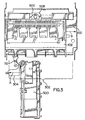
- FIGs. 1 and 2 provide a structural overview of a magazine movement system 100 according to a first preferred embodiment of the invention in which the magazine assembly is a normally stationary assembly, the picker assembly is a travelling assembly, and the autochanger is of the linear variety.
- a magazine assembly 102 includes a linear array of media slots 104. Each media slot 104 may be used to contain one media unit. In the illustrated embodiment, each of slots 104 is configured to receive one tape cartridge. In other embodiments, slots 104 may be configured to receive media units of a type other than tape cartridges. Magazine 102 is removably mounted to a car 106. Car 106 is retained in a track 108. Track 108 defines a linear path of movement for car 106.
- motion reversal assembly 110 is mounted to the bottom of track 108 and includes a lever 112 having an axis of rotation 200.
- Lever 112 has a slot 203 coupled to magazine assembly 102 via a pin 204 on the underside of car 106 as shown. (Other suitable coupling methods may also be used.)
- Lever 112 has a surface 114 that extends away from track 108 into the excursion path of a moving picker assembly. Further details about motion reversal assembly 110, including various alternative embodiments thereof, will be provided below.
- Magazine assembly 102 is biased toward the rest position illustrated in Figs. 1 and 2.
- this biasing is accomplished with a torsion spring 206.
- leg 208 of torsion spring 206 is retained by a notch in bearing surface 210 on the underside of track 108, and leg 212 of torsion spring 206 is retained under a lip 214 on lever 112.
- This arrangement urges lever 112 toward the clockwise direction (viewed from beneath, as in Fig. 12), which in turn urges magazine assembly 102 toward the rest position illustrated in Figs. 1 and 2.
- Other techniques may be used to bias magazine assembly 102 toward the rest position.
- magazine movement system 100 is shown adjacent to a traveling picker assembly 300.
- Picker assembly 300 has an excursion path 302 that includes an end portion 304.
- Surface 114 of lever 112 is disposed within end portion 304 of excursion path 302.
- magazine assembly 102 is shown in its rest position.
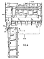
- picker assembly 300 engages surface 114 of lever 112. This moves lever 112 in the clockwise direction (viewed from the top as in Fig. 3), which in turn moves magazine assembly 102 away from the rest position toward direction B.
- Direction B is opposite to the direction of movement of picker assembly 300.
- the slot numbered "1" in magazine assembly 102 would be inaccessible by picker assembly 300 if it were not for magazine movement system 100.
- an automatic control system should be provided and calibrated such that picker assembly 300 will stop its movement in direction A when it is aligned with the media slot numbered "1" as shown in Fig. 4.
- the implementation of such a control system will not be described herein; its details are beyond the scope of the invention, and persons of ordinary skill in the art will be able to utilize well-known techniques to construct it suitably without undue experimentation.
- torsion spring 206 moves magazine assembly 102 toward direction A, returning it to its rest position as soon as picker assembly 300 disengages from lever 112.
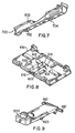
- FIG. 5 illustrates an optional implementation of magazine assembly 102 in which magazine 103 is removable from car 106.
- magazine 103 has been removed from car 106 by depressing spring-loaded magazine lock 500 and sliding magazine 103 away from car 106 along the line indicated by arrow 502. Magazine 103 is mounted to car 106 by sliding it along line 502 so that lips 506 pass underneath retaining guides 504. As sliding continues, a beveled surface (not shown) on the underside of magazine 103 depresses lock 500. Finally, lock 500 snaps into a locked position within lock retainer area 508 on the back side of magazine 103. (See Figs. 3 and 4.)
- Magazine lock 500 may be installed onto car 106 by inserting axles 610 through clearance slots 612 and then pushing them backwards until they snap into axle retainers 614.
- a compression spring 608 is placed between lock 500 and car 106 and is retained by recess 616 on car 106 and by recess 618 on the underside of lock 500. Installation is completed by rotating lock 500 down on spring 608 until tabs 620 (one on either side of lock 500) snap into clearance holes 622 formed in car 106.
- the material of track 108 defines a first wheel guide 600 along one side.
- track 108 and wheel guide 600 were fashioned from a single piece of sheet metal.
- a second wheel guide 700 may be fashioned within elongate member 602.
- elongate member 602 was made of plastic.
- wheels 606 and 607 are snapped onto car 106 as shown, car 106 may be placed onto track 108.
- Wheels 607 should be retained within wheel guide 600; pin 204 should extend downward through track slot 216; and car tabs 218 and 222 should be disposed within track slots 220 and 216, respectively.
- Elongate member 602 should be mounted onto track 108 so that it retains wheels 606.
- elongate member 602 was mounted to track 108 by inserting mounting tabs 702, 704 into slots 602, 604. Other suitable attachment methods may, of course, be used.
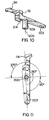
- Motion reversal assembly 110 will now be discussed in detail with reference to Figs. 10-11.
- Lever 112 and torsion spring 206 may be rotatably mounted to the underside of track 108 by any suitable means; for example, with a bolt.
- Cylindrical member 624 is disposed around axis of rotation 200 and fits inside torsion spring 206.
- Surface 114 should be disposed to engage picker assembly 300, and slot 203 should provide a sliding point of engagement between lever 112 and pin 204.
- surface 114 and slot 203 are angularly displaced from one another by approximately 180 degrees relative to axis of rotation 200.
- the radii extending from axis of rotation 200 to surface 114 and slot 203 were chosen to be approximately equal. This arrangement provided the desired reversal of motion between picker and magazine in substantially a 1:1 ratio. Other radii and angular displacements may be chosen to achieve alternative ratios. It is believed, however, that in all embodiments that employ a single lever 112 to implement motion reversal assembly 110, best results will be obtained when surface 114 is angularly displaced from slot 203 by not more than 270 degrees and not less than 90 degrees, as indicated in Fig. 11.
- motion reversal assembly 110 may be implemented using other means depending on the geometry of the magazine and picker assemblies in a given media autochanger.
- multiple levers, gears, motors or solenoids may be used to accomplish the task of moving the normally stationary assembly in the opposite direction of the traveling assembly when the traveling assembly enters an end portion of its excursion path. It is believed, however, that the single lever implementation will yield desirable cost savings over the alternative means just described.
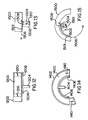
- FIG. 12 schematically summarizes the embodiment shown in Figs. 1-11.
- a normally stationary magazine assembly 1200 is retained on a linear track 1202.
- a traveling picker assembly 1204 moves along an excursion path 1206 adjacent to magazine assembly 1200 to access media units mounted in magazine assembly 1200.
- picker assembly 1204 travels to a point near the end of excursion path 1206, it engages motion reversal assembly 1208, which causes magazine 1200 to move in direction 1210 opposite to the direction of the picker assembly's movement.
- the result is to enable picker assembly 1204 to access one or more media slots in magazine assembly 1200 that would otherwise have been located in the picker assembly's dead space.
- Embodiment Two In the embodiment of Fig. 13, a normally stationary picker assembly 1304 is retained on a linear track 1302. A traveling magazine assembly 1300 moves along an excursion path 1306 adjacent to picker assembly 1304 so that picker assembly 1304 may access media units mounted in magazine assembly 1300. When magazine assembly 1300 travels to a point near the end of excursion path 1306, point 1301 engages motion reversal assembly 1308, which causes picker assembly 1304 to move in direction 1310 opposite to the direction of the magazine assembly's movement. The result is to enable picker assembly 1304 to access one or more media slots in magazine assembly 1300 that would otherwise have been located in dead space.
- a normally stationary magazine assembly 1400 is retained on a curved track 1402.
- a traveling picker assembly 1404 moves along an excursion path 1406 adjacent to magazine assembly 1400 to access media units mounted in magazine assembly 1400.
- picker assembly 1404 travels to a point near the end of excursion path 1406, it engages motion reversal assembly 1408, which causes magazine assembly 1400 to move in direction 1410 opposite to the direction of the picker assembly's movement. The result is to enable picker assembly 1404 to access one or more media slots in magazine assembly 1400 that would otherwise have been located in the picker assembly's dead space.
- a normally stationary picker assembly 1504 is retained on a curved track 1502.
- a traveling magazine assembly 1500 moves along an excursion path 1506 adjacent to picker assembly 1504 so that picker assembly 1504 may access media units mounted in magazine assembly 1500.
- point 1501 engages motion reversal assembly 1508, which causes picker assembly 1504 to move in direction 1510 opposite to the direction of the magazine assembly's movement. The result is to enable picker assembly 1504 to access one or more media slots in magazine assembly 1500 that would otherwise have been located in dead space.
- picker assembly is intended to include devices in which a read/write head is placed on or near the media units without withdrawing the media units from the magazine.
- picker assembly is also intended to include devices that remove media units from the magazine and place them in a drive.
Landscapes
- Automatic Tape Cassette Changers (AREA)
- Automatic Disk Changers (AREA)
Claims (10)
- Vorrichtung zu einem Beseitigen eines Bewegungsende-Totraums bei einem Medienautowechsler (100), die folgende Merkmale aufweist:eine Bewegungsanordnung, die einen Auslenkungsweg (302) mit einem Endabschnitt (304) aufweist;eine normalerweise stationäre Anordnung, die mit der Bewegungsanordnung zusammenwirkend betreibbar ist, um selektiv einen Aufnehmerzugriff auf Medieneinheiten bereitzustellen, die in einem Magazin gespeichert sind; undeine Bewegungsumkehranordnung (110), die mit der normalerweise stationären Anordnung gekoppelt und durch die Bewegungsanordnung in Eingriff nehmbar ist, wenn die Bewegungsanordnung in den Endabschnitt (304) des Auslenkungswegs (302) eintritt, wobei die Bewegungsumkehranordnung (110) betreibbar ist, wenn dieselbe so in Eingriff genommen ist, um die normalerweise stationäre Anordnung in die zu der Bewegung der Bewegungsanordnung entgegengesetzte Richtung zu bewegen.
- Die Vorrichtung gemäß Anspruch 1, bei der die normalerweise stationäre Anordnung das Magazin (102) aufweist und die Bewegungsanordnung den Aufnehmer (300) aufweist.
- Die Vorrichtung gemäß Anspruch 1, bei der die normalerweise stationäre Anordnung den Aufnehmer (1304) aufweist und die Bewegungsanordnung das Magazin (1300) aufweist.
- Die Vorrichtung gemäß Anspruch 1, bei der der Auslenkungsweg linear ist.
- Die Vorrichtung gemäß Anspruch 1, bei der der Auslenkungsweg bogenförmig ist.
- Ein Verfahren zum Beseitigen eines Bewegungsende-Totraums bei einem Medienautowechsler des Typs, bei dem eine Bewegungsanordnung mit einer normalerweise stationären Anordnung zusammenwirkend betreibbar ist, um einen Aufnehmerzugriff auf Medieneinheiten bereitzustellen, die in einem Magazin gespeichert sind, wobei das Verfahren folgende Schritte aufweist:Anordnen einer Bewegungsumkehranordnung (110) in einem Endabschnitt (304) eines Auslenkungswegs (302) der Bewegungsanordnung;Bewirken, daß die Bewegungsanordnung sich in den Endabschnitt (304) des Auslenkungswegs (302) bewegt, so daß dieselbe die Bewegungsumkehranordnung in Eingriff nimmt; undBewegen der normalerweise stationären Anordnung von einer Ruhestellung in eine Richtung, die der Bewegung der Bewegungsanordnung entgegengesetzt ist, ansprechend auf die Eingriffnahme der Bewegungsanordnung mit der Bewegungsumkehranordnung.
- Das Verfahren gemäß Anspruch 6, bei dem der Schritt des Bewegens der normalerweise stationären Anordnung ein Bewegen einer Magazinanordnung (102) aufweist.
- Das Verfahren gemäß Anspruch 6, bei dem der Schritt des Bewegens der normalerweise stationären Anordnung ein Bewegen einer Aufnehmeranordnung (1304) aufweist.
- Das Verfahren gemäß Anspruch 6, bei dem der Schritt des Bewegens der normalerweise stationären Anordnung ein lineares Bewegen der normalerweise stationären Anordnung aufweist.
- Das Verfahren gemäß Anspruch 6, bei dem der Schritt des Bewegens der normalerweise stationären Anordnung ein Bewegen der normalerweise stationären Anordnung entlang einem Bogen aufweist.
Applications Claiming Priority (2)
| Application Number | Priority Date | Filing Date | Title |
|---|---|---|---|
| US09/491,938 US6445652B1 (en) | 2000-01-26 | 2000-01-26 | Technique for eliminating end-of-travel dead space in media autochangers |
| US491938 | 2000-01-26 |
Publications (2)
| Publication Number | Publication Date |
|---|---|
| EP1120786A1 EP1120786A1 (de) | 2001-08-01 |
| EP1120786B1 true EP1120786B1 (de) | 2004-04-14 |
Family
ID=23954288
Family Applications (1)
| Application Number | Title | Priority Date | Filing Date |
|---|---|---|---|
| EP01300282A Expired - Lifetime EP1120786B1 (de) | 2000-01-26 | 2001-01-15 | Technik zur Beseitigung der Totraumsendstellung in einem automatischen Medienwechsler |
Country Status (4)
| Country | Link |
|---|---|
| US (1) | US6445652B1 (de) |
| EP (1) | EP1120786B1 (de) |
| JP (1) | JP3738185B2 (de) |
| DE (1) | DE60102722T2 (de) |
Families Citing this family (3)
| Publication number | Priority date | Publication date | Assignee | Title |
|---|---|---|---|---|
| US20040118215A1 (en) * | 2002-12-18 | 2004-06-24 | Hewlett-Packard Development Company, L.P. | Electromechanical apparatus with automatic self-test |
| US7251544B2 (en) * | 2003-07-01 | 2007-07-31 | Hewlett-Packard Development Company, L.P. | Storage system |
| US7307924B2 (en) * | 2004-10-27 | 2007-12-11 | Hewlett-Packard Development Company, L.P. | Systems and methods for cartridge identification |
Family Cites Families (6)
| Publication number | Priority date | Publication date | Assignee | Title |
|---|---|---|---|---|
| BE904766R (fr) | 1985-09-12 | 1986-09-01 | Staar Sa | Appareil pour la reproduction et/ou l'enregistrement successif et/ou selectif de supports d'informations. |
| US4911506A (en) * | 1989-07-24 | 1990-03-27 | Alexander Stefan | Device for storage and retrieval of disc-shaped articles |
| US5153862A (en) | 1989-11-06 | 1992-10-06 | North American Philips Corporation | Cassette for storing, moving and loading optical storage disk cartridges |
| US5337297A (en) * | 1993-05-04 | 1994-08-09 | Tandberg Data Storage A/S | Magazine drawer manipulation system for a data carrier loader |
| JPH0850755A (ja) * | 1994-08-04 | 1996-02-20 | Pioneer Electron Corp | ディスクオートチェンジャー |
| JPH10255372A (ja) * | 1997-03-17 | 1998-09-25 | Fujitsu Ltd | ライブラリ装置 |
-
2000
- 2000-01-26 US US09/491,938 patent/US6445652B1/en not_active Expired - Fee Related
-
2001
- 2001-01-15 DE DE60102722T patent/DE60102722T2/de not_active Expired - Lifetime
- 2001-01-15 EP EP01300282A patent/EP1120786B1/de not_active Expired - Lifetime
- 2001-01-25 JP JP2001017027A patent/JP3738185B2/ja not_active Expired - Fee Related
Also Published As
| Publication number | Publication date |
|---|---|
| JP3738185B2 (ja) | 2006-01-25 |
| EP1120786A1 (de) | 2001-08-01 |
| JP2001229594A (ja) | 2001-08-24 |
| US6445652B1 (en) | 2002-09-03 |
| DE60102722T2 (de) | 2005-04-21 |
| DE60102722D1 (de) | 2004-05-19 |
Similar Documents
| Publication | Publication Date | Title |
|---|---|---|
| US5544146A (en) | Cartridge handling system | |
| KR910006028Y1 (ko) | 디스크 카트리지 | |
| JP3305275B2 (ja) | カートリッジ取り扱いシステム | |
| EP0623924B1 (de) | Magazin-Schublade-Manipulationssystem für Datenträgerladevorrichtung | |
| US5768047A (en) | Cartridge library with duel-sided rotatable spit having latch member extending through aperture in circular toothed end wall | |
| EP0877366B1 (de) | Datenkassettenbehälter-zu-Lagergestell Referenzierungsverfahren und -gerät | |
| US5795042A (en) | Receiver and magazine assembly for storage library system | |
| JPH11316997A (ja) | カ―トリジ係合アセンブリ | |
| US6028733A (en) | Data cartridge caddy-to-storage rack interlock and release system | |
| US5926341A (en) | Data cartridge interlock and release system | |
| US6445652B1 (en) | Technique for eliminating end-of-travel dead space in media autochangers | |
| US5993045A (en) | Data cartridge caddy presence sensing method and apparatus | |
| EP1271504B1 (de) | Automatisches Bibliotheksystem mit kompaktem Formfaktor und mit automatischer Ladung von Bandkassetten | |
| CA1157148A (en) | Cartridge-loading apparatus for tape recorder drives | |
| US5999500A (en) | Data cartridge interlock release actuator system | |
| US7334978B2 (en) | Cartridge-handling apparatus for a media storage system | |
| US20040133902A1 (en) | Apparatus for translating a cartridge access device | |
| US6775093B1 (en) | Data cartridge-to-caddy referencing system for a data cartridge handling mechanism within an autochanger | |
| EP1136995B1 (de) | Strichkodeleservorrichtung und ihres Benutzungsverfahren in einem Medienauto-wechsler | |
| EP0898274B1 (de) | Wiedergabegerät für Aufzeichnungsmedien | |
| EP1063646B1 (de) | Gerät zum Verschieben einer Kassettenübergabeeinheit | |
| US5493461A (en) | Storage media lockout device for a computer mass storage media drive | |
| US7672077B2 (en) | Auto loading device for data storage cartridges | |
| CN1700344A (zh) | 光盘驱动装置 | |
| JPH0453058A (ja) | カセット装着装置 |
Legal Events
| Date | Code | Title | Description |
|---|---|---|---|
| PUAI | Public reference made under article 153(3) epc to a published international application that has entered the european phase |
Free format text: ORIGINAL CODE: 0009012 |
|
| AK | Designated contracting states |
Kind code of ref document: A1 Designated state(s): DE FR GB |
|
| AX | Request for extension of the european patent |
Free format text: AL;LT;LV;MK;RO;SI |
|
| 17P | Request for examination filed |
Effective date: 20020109 |
|
| AKX | Designation fees paid |
Free format text: DE FR GB |
|
| 17Q | First examination report despatched |
Effective date: 20020919 |
|
| GRAP | Despatch of communication of intention to grant a patent |
Free format text: ORIGINAL CODE: EPIDOSNIGR1 |
|
| GRAS | Grant fee paid |
Free format text: ORIGINAL CODE: EPIDOSNIGR3 |
|
| GRAA | (expected) grant |
Free format text: ORIGINAL CODE: 0009210 |
|
| AK | Designated contracting states |
Kind code of ref document: B1 Designated state(s): DE FR GB |
|
| REG | Reference to a national code |
Ref country code: GB Ref legal event code: FG4D |
|
| REF | Corresponds to: |
Ref document number: 60102722 Country of ref document: DE Date of ref document: 20040519 Kind code of ref document: P |
|
| ET | Fr: translation filed | ||
| PLBE | No opposition filed within time limit |
Free format text: ORIGINAL CODE: 0009261 |
|
| STAA | Information on the status of an ep patent application or granted ep patent |
Free format text: STATUS: NO OPPOSITION FILED WITHIN TIME LIMIT |
|
| 26N | No opposition filed |
Effective date: 20050117 |
|
| PGFP | Annual fee paid to national office [announced via postgrant information from national office to epo] |
Ref country code: FR Payment date: 20100205 Year of fee payment: 10 |
|
| PGFP | Annual fee paid to national office [announced via postgrant information from national office to epo] |
Ref country code: GB Payment date: 20100125 Year of fee payment: 10 Ref country code: DE Payment date: 20100127 Year of fee payment: 10 |
|
| GBPC | Gb: european patent ceased through non-payment of renewal fee |
Effective date: 20110115 |
|
| REG | Reference to a national code |
Ref country code: FR Ref legal event code: ST Effective date: 20110930 |
|
| PG25 | Lapsed in a contracting state [announced via postgrant information from national office to epo] |
Ref country code: FR Free format text: LAPSE BECAUSE OF NON-PAYMENT OF DUE FEES Effective date: 20110131 |
|
| PG25 | Lapsed in a contracting state [announced via postgrant information from national office to epo] |
Ref country code: GB Free format text: LAPSE BECAUSE OF NON-PAYMENT OF DUE FEES Effective date: 20110115 |
|
| REG | Reference to a national code |
Ref country code: DE Ref legal event code: R119 Ref document number: 60102722 Country of ref document: DE Effective date: 20110802 |
|
| PG25 | Lapsed in a contracting state [announced via postgrant information from national office to epo] |
Ref country code: DE Free format text: LAPSE BECAUSE OF NON-PAYMENT OF DUE FEES Effective date: 20110802 |