EP1120773A2 - Verbesserungen in oder bezüglich zu Glocken - Google Patents
Verbesserungen in oder bezüglich zu Glocken Download PDFInfo
- Publication number
- EP1120773A2 EP1120773A2 EP00420214A EP00420214A EP1120773A2 EP 1120773 A2 EP1120773 A2 EP 1120773A2 EP 00420214 A EP00420214 A EP 00420214A EP 00420214 A EP00420214 A EP 00420214A EP 1120773 A2 EP1120773 A2 EP 1120773A2
- Authority
- EP
- European Patent Office
- Prior art keywords
- bell
- side portion
- frequencies
- modes
- mouth
- Prior art date
- Legal status (The legal status is an assumption and is not a legal conclusion. Google has not performed a legal analysis and makes no representation as to the accuracy of the status listed.)
- Withdrawn
Links
- 238000000034 method Methods 0.000 claims abstract description 84
- 230000003247 decreasing effect Effects 0.000 claims description 10
- 238000013459 approach Methods 0.000 claims description 4
- 230000035945 sensitivity Effects 0.000 description 19
- 230000008859 change Effects 0.000 description 16
- 238000013461 design Methods 0.000 description 13
- 239000013598 vector Substances 0.000 description 10
- 230000000694 effects Effects 0.000 description 7
- 230000006870 function Effects 0.000 description 6
- 230000033001 locomotion Effects 0.000 description 5
- 230000004048 modification Effects 0.000 description 5
- 238000012986 modification Methods 0.000 description 5
- 238000004458 analytical method Methods 0.000 description 4
- 230000006399 behavior Effects 0.000 description 4
- 239000007787 solid Substances 0.000 description 4
- 238000001228 spectrum Methods 0.000 description 4
- 238000006073 displacement reaction Methods 0.000 description 2
- 230000001788 irregular Effects 0.000 description 2
- 230000008447 perception Effects 0.000 description 2
- 230000003595 spectral effect Effects 0.000 description 2
- 238000013519 translation Methods 0.000 description 2
- 238000012935 Averaging Methods 0.000 description 1
- 230000009471 action Effects 0.000 description 1
- 238000007792 addition Methods 0.000 description 1
- 230000003796 beauty Effects 0.000 description 1
- 238000000205 computational method Methods 0.000 description 1
- 230000001419 dependent effect Effects 0.000 description 1
- 230000002349 favourable effect Effects 0.000 description 1
- 230000014509 gene expression Effects 0.000 description 1
- 238000004519 manufacturing process Methods 0.000 description 1
- 238000000053 physical method Methods 0.000 description 1
- 230000008569 process Effects 0.000 description 1
- 210000003462 vein Anatomy 0.000 description 1
Images


Classifications
-
- G—PHYSICS
- G10—MUSICAL INSTRUMENTS; ACOUSTICS
- G10K—SOUND-PRODUCING DEVICES; METHODS OR DEVICES FOR PROTECTING AGAINST, OR FOR DAMPING, NOISE OR OTHER ACOUSTIC WAVES IN GENERAL; ACOUSTICS NOT OTHERWISE PROVIDED FOR
- G10K1/00—Devices in which sound is produced by striking a resonating body, e.g. bells, chimes or gongs
- G10K1/06—Devices in which sound is produced by striking a resonating body, e.g. bells, chimes or gongs the resonating devices having the shape of a bell, plate, rod, or tube
- G10K1/07—Devices in which sound is produced by striking a resonating body, e.g. bells, chimes or gongs the resonating devices having the shape of a bell, plate, rod, or tube mechanically operated; Hand bells; Bells for animals
- G10K1/071—Hand bells; Bells for animals
-
- G—PHYSICS
- G10—MUSICAL INSTRUMENTS; ACOUSTICS
- G10K—SOUND-PRODUCING DEVICES; METHODS OR DEVICES FOR PROTECTING AGAINST, OR FOR DAMPING, NOISE OR OTHER ACOUSTIC WAVES IN GENERAL; ACOUSTICS NOT OTHERWISE PROVIDED FOR
- G10K1/00—Devices in which sound is produced by striking a resonating body, e.g. bells, chimes or gongs
- G10K1/28—Bells for towers or the like
- G10K1/30—Details or accessories
- G10K1/32—Sounding members; Clappers or other strikers
-
- Y—GENERAL TAGGING OF NEW TECHNOLOGICAL DEVELOPMENTS; GENERAL TAGGING OF CROSS-SECTIONAL TECHNOLOGIES SPANNING OVER SEVERAL SECTIONS OF THE IPC; TECHNICAL SUBJECTS COVERED BY FORMER USPC CROSS-REFERENCE ART COLLECTIONS [XRACs] AND DIGESTS
- Y10—TECHNICAL SUBJECTS COVERED BY FORMER USPC
- Y10T—TECHNICAL SUBJECTS COVERED BY FORMER US CLASSIFICATION
- Y10T29/00—Metal working
- Y10T29/49—Method of mechanical manufacture
- Y10T29/4957—Sound device making
- Y10T29/49574—Musical instrument or tuning fork making
Definitions
- the invention relates to the field of bell design and manufacture.
- a bell is a solid body that undergoes vibration and radiates energy into the air to make sound.
- a bell is typically a hollow body having an opening at one end (the "mouth”).
- bells are typically axisymmetric.
- Oriental bells having an oval (as opposed to a circular) cross-section are known.
- a circular line on the circumference of the bell, in a plane normal to the axis of symmetry, is called a "ring”.
- a line on the surface of the bell, in a plane parallel to, and passing through, the axis of symmetry, is called a "meridian”.
- a direction along a meridian is referred to as a "meridonal direction”.
- the vibratory motion of a bell may be regarded as a linear combination of different motions of the bell known as the bell's "normal modes of vibration", or, simply, "modes".
- Each mode of vibration represents a particular vibratory shape and takes place at a single frequency of vibration.
- the rich sound of a bell may be regarded as being the superposition of many different frequency components, with each frequency being due to its associated mode of vibration.
- the acoustically important modes are those in which displacement occurs in a direction normal to the bell's surface, as these modes are able to most efficiently radiate their energy in the air in the form of sound.
- modes is a reference only to modes in which vibration occurs in a direction normal to the bell's surface.
- frrequencies is a reference only to frequencies due to modes in which vibration occurs in a direction normal to the bell's surface.
- the amplitude of vibration of higher frequency modes decays more rapidly than that for lower frequency modes so that after a short time (typically of the order of one second) only several of the lowest frequency modes continue to be heard.
- a short time typically of the order of one second
- complex psycho-acoustic effects are generally believed to make only the several lowest frequency modes musically important and/or discernible.
- modes are referred to as an ordered pair ( m,n ) where m is the number of meridonal nodal lines and n is the number of nodal rings.
- the (2,0) mode is the lowest frequency acoustically important mode ("the fundamental").
- the fundamental the lowest frequency acoustically important mode
- a reference to the first, say, three, modes is a reference to the lowest frequency mode, the second lowest frequency mode and the third lowest frequency mode.
- Other references to the first number of modes are to be construed similarly.
- a reference to the "mode sequence" for a bell is a reference to a list of the modes of the bell, in order of the frequency of the modes and starting with the lowest frequency mode.
- references to a "frequency sequence” are references to a list of the modal frequencies of a bell starting with the lowest modal frequency.
- references to frequencies "being tuned”, and similar expressions are references to modal frequencies which are desired to be modified to substantially adopt particular values.
- the first five frequencies are all "being tuned” or "to be tuned”.
- a reference to a "tuned bell” is a reference to a bell that has modal frequencies that have been tuned.
- the sound quality or timbre of a bell is dependent upon the frequency ratios and relative strengths of the different frequency components in the sound emitted by the bell. Consequently, it has long been the goal of bell founders to make bells where the frequencies of the lowest several modes are tuned as nearly as possible to particular frequency ratios. For example, church bells are typically tuned so that the first five modes have frequencies that are as near as possible to the ratios (with respect to the fundamental): 1, 2, 2.4, 3 and 4. In this instance, the first five modes have traditionally been considered to be the modes (2,0), (2,1), (3,1), (3,1#) and (4,1).
- This tuning system is referred to as the "minor third" because the frequency of the third mode is musically at an interval of a minor third above the frequency of the second mode (and an interval of a minor third plus an octave from the frequency of the first mode).
- Handbells are generally smaller than church bells, and generally have a different tuning. Generally, only two modes are tuned in handbells. In the so-called English tuning of handbells, the frequency of the second mode (usually the (3,0) mode) is tuned to three times the frequency of the fundamental (the (2,0) mode). Others tune the second mode to 2.4 times the frequency of the fundamental to give the bell a minor third character.
- the frequency of the second mode usually the (3,0) mode
- Others tune the second mode to 2.4 times the frequency of the fundamental to give the bell a minor third character.
- Minor third bells generally have a curved outer wall of approximately hyperbolic shape in the meridonal direction. As the wall approaches the mouth of the bell, it generally includes a relatively thick portion, prior to termination of the wall at the mouth. This thicker portion is often referred to as the "sound bow”. Handbells generally also have a thicker portion at around the same location, often referred to as the "lip”.
- Each has a substantially visually different profile to that of the known minor third bell shapes.
- the major third bells have a curved outer surface with at least two extra turning points in the meridonal direction in comparison to the minor third bell shape.
- a bell with the greatest clarity (and, possibly, beauty) of sound would be an harmonic bell, that is a bell having at least the first several modal frequencies in the ratios 1, 2, 3, etc. Due to the complexity of bell vibrations, it has hitherto been considered impossible to design an harmonic bell. Indeed, the art of bell founding is known to date beyond 1600BC. However, an ideal or harmonic bell has never, until now, been produced.
- a bell with modes in an harmonic sequence would be expected to have many musical advantages over currently known bells. It is generally believed that pitch perception in humans is based on finding a best fit of an harmonic sequence to the perceived spectra of a sound, and attributing perceived pitch to the fundamental frequency of that, fitted, harmonic sequence. Bells with vibrational modes in an harmonic sequence would therefore be expected to create less ambiguous pitch perceptions.
- Finite element methods for numerically estimating the normal modes of a solid body, and their associated frequencies, are known.
- the body is notionally divided into many elements.
- the geometry or layout of this division is called a "mesh”.
- Individual elements are defined by so-called “nodes” which are points on the boundaries of elements.
- nodes are points on the boundaries of elements.
- the finite element method is capable of estimating the mode shapes and frequencies of a body only for a particular, given, geometry.
- a given modal frequency would be the "objective function" and the optimisation method would use appropriate rules to modify the shape of the bell from a given starting shape, until the analysis method (eg the finite element method) indicated that the objective function had obtained the objective (ie that the bell had attained a shape having the desired modal frequencies).
- the analysis method eg the finite element method
- a reference to the frequencies of the first at least three modes being substantially in an harmonic sequence means that the frequencies of the first at least three modes substantially conform to the ratios 1, 2, 3 etc. (with respect to, and including, the fundamental).
- a bell wherein the frequencies of the first several modes are substantially in an harmonic sequence is referred to hereafter as "an harmonic bell".
- the bells and bell designs of the present invention have a top portion, a side portion and a mouth, the side portion extending from the top portion to the mouth.
- a bell wherein the first at least three frequencies are substantially in an harmonic sequence.
- a bell wherein the first at least four frequencies are substantially in an harmonic sequence.
- a bell wherein the first at least five frequencies are substantially in an harmonic sequence.
- all the tuned frequencies of the harmonic bell are due to modes with no ring nodes.
- the frequencies due to modes with no ring nodes are all below any frequencies due to modes with ring nodes.
- the outer surface of the side portion of the harmonic bell may be generally in the form of a truncated circular cone.
- the outer surface of the side portion of the harmonic bell may be generally convex. It may substantially consist of a generally convex portion and a portion generally in the form of a circular cylinder. It may substantially consist of a generally convex portion and a portion generally in the form of a truncated circular cone.
- the inner surface of the side portion of the harmonic bell may be generally in the form of a truncated circular cone.
- the inner surface of the side portion of the harmonic bell may be generally concave. It may substantially consist of a generally concave portion and a portion generally in the form of a circular cylinder. It may substantially consist of a generally concave portion and a portion generally in the form of a truncated circular cone.
- the side portion of the harmonic bell may be generally tapered.
- a bell wherein the first at least three frequencies are substantially in an harmonic sequence, the bell being produced in accordance with a design according to a method of the present invention.
- a bell wherein the first at least three frequencies are substantially in an harmonic sequence, the bell being copied from a bell produced in accordance with a design according to a method of the present invention.
- a method for designing a bell having the first at least three frequencies substantially in an harmonic sequence comprising the steps of selecting an initial bell shape and using the initial bell shape in an optimisation procedure for modifying the bell shape such that it becomes an harmonic bell.
- the initial bell shape is such that the frequencies to be tuned are due to modes with no ring nodes.
- the initial bell shape is such that, of the frequencies to be tuned, all the frequencies due to modes without ring nodes are below any frequencies due to modes with ring nodes.
- the initial bell shape is preferably selected by introducing one or more of the following shape features to a first bell shape:
- the initial bell shape may be a rescaled existing bell shape for an harmonic bell.
- the optimisation procedure according to the present invention will be described below.
- the higher modal frequencies or frequency ratios need not be as close to the desired values as for lower modal frequencies or frequency ratios.
- one aspect of the present invention provides shape features for a bell shape to generate an initial bell shape for producing an harmonic bell in an optimisation procedure, the initial bell shape having frequencies suitably close to desired frequencies.
- the present invention provides shape features for a bell shape to generate an initial bell shape for producing an harmonic bell in an optimisation procedure, the initial bell shape having frequency ratios suitably close to desired frequency ratios.
- the problem in using an optimisation procedure to produce an harmonic bell from an initial bell shape of known bell shape, given that the initial bell shape for use in the optimisation procedure must have modal frequencies or frequency ratios that are suitably close to their desired values, is that the first several modes in the mode sequence of known bell shapes include both modes without ring nodes (ie ( m ,0) modes) and modes with ring nodes (ie ( m,n ) modes where n ⁇ 1), wherein at least one mode with at least one ring node is interspersed between modes without ring nodes.
- This distribution of modes in the mode sequence makes it extremely difficult, if not practically impossible, to choose an appropriate initial bell shape for optimisation in the absence of being able to control, at least to some extent, the nature of the mode distribution in the mode sequence.
- the problem in generating an harmonic bell having more than the first three modes tuned (ie tuned to being substantially in an harmonic sequence) using an initial bell shape of a particular circular cylinder was that the first five modes were in the order (starting with the lowest frequency) (2,0), (3,0), (2,1), (4,0), (5,0).
- the frequency of the (3,0) mode and the frequency of the (4,0) mode cannot attain a sufficiently large frequency ratio during optimisation for the ratio 2:4 to be established as required.
- the frequencies of ( m ,0) modes on either side of a ring mode cannot attain a sufficiently large frequency ratio for the appropriate harmonic relationship to be established.
- the present inventors have realised that this problem may be solved to provide suitable initial bell shapes for producing harmonic bells in an optimisation procedure by applying suitable shape features to an initial bell shape so that the mode sequence of the initial bell shape is as desired.
- suitable shape features it is generally more important that the lower modal frequencies of initial bell shapes are close to their desired values than is the case for higher modal frequencies. For this reason, it is generally more important that the mode sequence of the lower frequency modes of initial bell shapes is in a desired modal sequence than that the modal sequence for higher frequency modes is in a desired modal sequence.
- the lower frequency modes of an initial bell shape are in a desired modal sequence, it may not be necessary to have regard to the modal sequence of higher frequency modes, even where some higher frequency modes are to be tuned.
- an initial bell shape for optimisation in which at least the lowest few frequencies being tuned all correspond to ( m ,0) modes. That is, at least the first few frequencies being tuned all correspond to modes with no ring nodes.
- an harmonic bell with five modes in tune may be obtained by the method of the present invention using an initial bell shape where the first five modes are (2,0), (3,0), (4,0), (5,0), and (6,0).
- an harmonic bell with seven modes in tune may be obtained by the method of the present invention using an initial bell shape where the first seven modes are (2,0), (3,0), (4,0), (5,0), (6,0), (2,1), and (3,1).
- the ultimate bell shape will typically have a mode sequence as follows: (2,0), (3,0), (4,0), (5,0), (6,0), (7,0), and (8,0).
- the optimisation caused the frequencies of the (7,0) and (8,0) modes to drop below the frequencies of the (2,1) and (3,1) modes and the fact that the first five modes were all modes with no ring nodes was sufficient to render the initial bell shape suitable.
- a method for designing a bell wherein the frequencies of the first at least three modes are substantially in an harmonic sequence comprising the steps of selecting an initial bell shape and using the initial bell shape in an optimisation procedure according to the present invention, the initial bell shape being such that the frequencies of at least the first three modes each have no ring nodes.
- the second reference to "at least three modes" is not necessarily a reference to the same modes as referred to by the first reference to "at least three modes”.
- a method for designing a bell wherein the frequencies of the first at least three modes are substantially in an harmonic sequence comprising the steps of selecting an initial bell shape and using the initial bell shape in an optimisation procedure according to the present invention, the initial bell shape being such that, of the number of frequencies to be tuned, all the frequencies due to modes without ring nodes are below all the frequencies due to modes with ring nodes.
- the initial bell shape if five modes are to be tuned, then the initial bell shape must be such that, of the first five modal frequencies, all the frequencies due to modes without ring nodes are below all the frequencies due to modes with ring nodes (if any).
- the present invention accordingly provides, in a further aspect, shape features for applying to an initial bell shape so that the modes associated with the frequencies being tuned are separated such that, of the number of frequencies to be tuned, all the frequencies due to modes without ring nodes are below all the frequencies due to modes with ring nodes.
- Conicity is a shape feature according to the present invention.
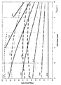
- Conicity refers to the angle of inclination of the side portion to the axis of symmetry of the bell (represented by numeral 2 in figure 6).
- Figure 1 shows how the frequency ratios of the frequencies of the first several modes vary with cone angle, while other parameters remain unchanged, for an example bell shape with the following parameters. (These figures were determined using a finite element program.)
- the top portion is flat and has an equal thickness to the wall thickness of the side portion, namely 10mm.
- the length of the side portion, measured in a direction parallel to the side portion (represented by numeral 3 in figure 6), is 210mm.
- the radius of the top portion is 36mm, measured with respect to the top face of the top portion (represented by numeral 1 in figure 6).
- the frequency ratios of the first several ( m ,2) modes are increased, at a higher rate than the rate of increase in frequency ratios of the ( m ,1) modes.
- the more ( m ,0) modes are included in the mode sequence before a mode with a ring node appears in the sequence. For example, as can be seen from figure 1, at 20° the first two modes are (m,0) modes, at 30° the first three modes are (m,0) modes and at 40° the first four modes are (m,0) modes.
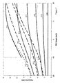
- Taper is a shape feature according to the present invention. Taper refers to the angle of inclination of the inner surface of the side portion to the outer surface of the side portion. Uniform wall thickness is, of course, zero taper. The sign convention is adopted such that the taper is positive for the case where the side portion is thinner near the mouth than near the top portion.
- Figure 2 shows how the frequency ratios of the frequencies of the first several modes vary with taper, while other parameters remain unchanged, for an example bell shape with the following parameters. (These figures were determined using a finite element program.) The bell is essentially a truncated circular cone, with a cone angle of 35 degrees. The top portion is flat and has a thickness of 10mm.
- the length of the side portion measured in a direction parallel to the side portion, is 210mm.
- the radius of the top portion is 36mm, measured with respect to the top face of the top portion.
- the taper is generated by rotating the line defining the inner surface of the side portion about its midpoint.
- Numeral 6 in Figure 6 represents the midpoint about which the line is rotated and numeral 7 indicates the position of the inner surface following the introduction of the taper.
- the abscissa values of Figure 2 represent the decreased (or increased thickness) of the side portion at the extremity of the side portion adjacent the mouth.
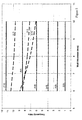
- Wall curvature is a shape feature according to the present invention. It has been found that introducing curvature into the side portion of a bell in the form of a truncated cone has an effect upon the relative frequency ratios of the ( m ,0) modes with respect to the modes with ring nodes. In what follows, the descriptions “convex” and “concave” are with respect to viewing the inside surface of the side portion of the bell.
- Figure 3 shows how the frequency ratios of the frequencies of the first several modes vary with particular changes in the curvature of the side portion, while other parameters remain unchanged, for an example bell shape with the following parameters. (These figures were determined using a finite element program.)
- the curvature changes are to be viewed as changes to a shape that is essentially a truncated circular cone, with a cone angle of 35 degrees.
- the top portion is flat and has a thickness of 10mm.
- the length of the side portion, measured in a direction parallel to the side portion, is 210mm.
- the thickness of the side portion is also 10mm.
- the radius of the top portion is 36mm, measured with respect to the top face of the top portion.
- the curvature changes are defined by first defining a point being a translation normal to the surface of the side portion of the midpoint of the side portion, (represented by the translation of numeral 4 to numeral 4' in figure 6).
- the shape changes are to fit an arc of a circle to the translated midpoint and the two end points of the initial line (see the arc of a circle represented by numeral 5 in figure 6).
- the abscissa values of Figure 3 represent the displacement of the midpoint of the side portion normal to the initial straight line.
- the sign convention is such that concavity (with respect to the inside of the bell) is positive and convexity is negative.
- introducing convexity into the side portion causes the frequency ratios of all of the first several modes to decrease, but the frequency ratios of the modes with ring nodes decrease faster than the frequency ratios of the ( m ,0) modes.
- introducing concavity into the side portion causes the frequency ratios of all of the first several modes to increase, but the frequency ratios of the modes with ring nodes increase faster than the frequency ratios of the ( m ,0) modes. Consequently, as the degree of concavity increases, the more (m,0) modes are included in the mode sequence before a mode with a ring node appears in the sequence.
- Varying the length of the side portion of a bell is a shape feature according to the present invention.
- Figure 4 shows how the frequency ratios of the frequencies of the first several modes vary with the length of the side portion, while other parameters remain unchanged, for an example bell shape with the following parameters. (These figures were determined using a finite element program.)
- the bell is essentially a truncated circular cone, with a cone angle of 35 degrees.
- the top portion is flat and has a thickness of 10mm.
- the radius of the top portion is 36mm, measured with respect to the top face of the top portion.
- the side portion is 10mmm thick.
- Varying the wall thickness of the side portion of a bell is a shape feature according to the present invention.
- Figure 5 shows how the frequency ratios of the frequencies of the first several modes vary with wall thickness, while other parameters remain unchanged, for an example bell shape with the following parameters. (These figures were determined using a finite element program.)
- the bell is essentially a truncated circular cone, with a cone angle of 35 degrees.
- the top portion is flat and has a thickness of 10mm.
- the length of the side portion, measured in a direction parallel to the side portion, is 210mm.
- the radius of the top portion is 36mm, measured with respect to the top face of the top portion.
- more than one shape feature according to the present invention will need to be utilised in order to achieve an initial bell shape where more than the first four modes are ( m ,0) modes.
- a method for designing a tuned bell wherein the frequencies of the first at least three modes are tuned comprising the steps of selecting an initial bell shape and using the initial bell shape in an optimisation procedure according to the present invention, the initial bell shape being such that the frequencies of at least the first three modes each have no ring nodes, the initial bell shape being substantially in the form of a truncated circular cone.
- the optimisation procedure according to the present invention comprises the steps of
- an initial shape is suitable can easily be determined by attempting an optimisation. If an optimisation is unsuccessful (ie it is not possible to obtain the desired objectives) then the initial shape is not suitable. For example, if, say, the sixth frequency cannot be sufficiently reduced during optimisation for its frequency ratio to be approximately 6.0, then it will be appropriate to first determine the mode type of the sixth frequency in order to decide what action to take. If the sixth frequency is an (m,0) mode (it would therefore be expected to be the (7,0) mode), the shape can be modified by applying one or more shape features that tend to reduce the frequency ratios of (m,0) modes, for example increasing the cone angle, increasing the wall taper or increasing the length. If the sixth frequency is not an (m,0) mode, it may be appropriate to introduce shape features for the purpose of reducing the frequency ratios of (m,0) modes relative to other mode types such that the sixth frequency becomes an (m,0) mode.
- the other (m,0) frequencies when the objective frequency is pushed up or down (by specifying an objective that is higher or lower than the current value) then the other (m,0) frequencies generally tend to move in the direction that they would move if actually joined by the imagined rigid connection, and the other (m,0) frequencies generally tend to move a distance approximately of the order that they would move if actually joined by the imagined rigid connection.
- the constraint does not move and points near the fulcrum generally move less than points further away from the fulcrum.
- the "lever principle” referred to above may be more clearly understood with reference to the example given below.
- the “lever principle” is presented as a guide to making suitable choices when carrying out optimisations.
- the “principle” is not necessarily universally applicable but the present inventors have found it a useful guide in carrying out the optimisations for the two harmonic bells of which details are presented in this specification. Examples of the application of this "principle” are given in example 1, below.
- a simple way of finding an appropriate starting shape for conducting an optimisation according to the present invention is to take the shape of an harmonic bell already designed in accordance with the present invention, to rescale it, and to then use it as a starting point for a further optimisation to generate an harmonic bell design for a differently sized (and hence pitched) bell.
- Harmonic bells of different pitch may be generated by rescaling harmonic bells already designed in accordance with the present invention. If the rescaling has not caused the tuned modes to lose their harmonic tuning, then no further optimisation is necessary and a differently pitched harmonic bell may then simply be constructed in accordance with the rescaled design.
- This line can be used as a guide in selecting a scaling factor to generate a bell of given fundamental frequency from using a rescaled known bell shape as an initial bell shape for optimisation.
- This method may in some cases be an approximation only and in these cases it would be expected that some experimentation would be required to select an appropriate scaling factor to be able to generate a new harmonic bell of a particular fundamental frequency with an existing harmonic bell shape.
- the method for determining the frequencies of the modes of the current bell shape in an optimisation procedure according to the present invention is the finite element method.
- the optimisation method must determine the so-called "step direction" at each iteration.
- the step direction is the modification to be made to the bell shape during the given iteration.
- the optimisation method uses gradient methods to determine the step direction.
- the method of conjugate gradient is used.
- the method of steepest descent may be used.
- the method for determining the frequencies of the modes of the current bell shape is the finite element method and the optimisation method effects shape modifications during each iteration by way of moving the nodes of the finite element mesh defining the bell.
- the nodes of the finite element mesh refer to the points where elements are connected to one another and are not to be confused with the nodes occurring in the various modes of vibration of a bell.
- the sensitivities are calculated at each node of the finite element mesh.
- the sensitivity at a particular node is a measure of the rate of change of the objective (ie of the frequency of the chosen mode) with respect to a change of the node position.
- the meaning of the sensitivity is further discussed below in relation to cartesian coordinates ( x , y , z ) with corresponding unit vectors i, j and k. It will be readily appreciated by those skilled in the art that other coordinate systems may be used.
- the rate of change of the objective with respect to a change of nodal position in each coordinate direction is calculated. If the value of the objective is designated P , then the rate of change of the objective with respect to a change of position of the node in the x direction is ⁇ P / ⁇ x .
- the rates of change of the objective with respect to a change of position of the node in the y and z directions are, respectively, ⁇ P / ⁇ y and ⁇ P / ⁇ z .
- the sensitivity at a particular node is defined as the vector ⁇ P / ⁇ x i + ⁇ P / ⁇ y j + ⁇ P / ⁇ z k (ie the sensitivity is the gradient of the scalar field P ).
- the sensitivity vector points in the direction in which movement of the node will cause the greatest change to the objective.
- the magnitude of the sensitivity represents the maximum possible rate of change of the objective that can result from a movement of the node in question, which rate of change may generally only actually occur if the node is moved in the direction of the sensitivity vector.
- the outer surface of the side portion of the bell is constrained and only the position of the inner surface of the side portion may be changed by the optimisation method.
- the inner surface may only move in the radial direction with respect to the axis of symmetry of the bell, that is, towards or away from the axis.
- all circumferential points on the inner (or outer) surface at a given axial location must be moved by the same amount in the radial direction (known as an "averaging constraint").
- the step direction is determined following determination of the sensitivities as follows. Firstly, the sensitivities for all circumferential locations at a given axial location are averaged in cylindrical coordinates to determine an average sensitivity vector for that axial location. Next, the magnitudes of all the averaged sensitivity vectors for each axial location are normalised with respect to the magnitude of the averaged sensitivity vector with the largest magnitude. A preliminary step direction is then determined as the shape of the normalised averaged sensitivity vectors.
- This preliminary step direction is used to calculate the final step direction after taking into account the effect of the performance constraints. For example, if the shape of the bell has already been modified so that the first two modes are in the frequency ratio 1:2, then the optimisation for the frequency of the third mode should be subject to the constraints that the frequencies of the first two modes do not change. In the preferred embodiment, these constraints are effected by determining the sensitivities with the respect to the constrained modes in the same manner as for determining the sensitivities for the objective. Because a shape change normal to the sensitivity vector for the constrained mode will cause the frequency of that mode to change the least, the preliminary step direction may be projected onto the hypersurface normal to the sensitivity vector for the constrained mode to determine a refined step direction. Once this process has been repeated with respect to all performance constraints (in the example, the frequencies of the first two modes), the resulting refined step direction will be the step direction for that iteration.
- the step size may be user specified or based on a suitable optimisation of the step size with respect to the objective, before the step is taken.
- Table 1 sets out the results of an optimisation carried out on an initial bell shape generated as follows.
- the bell shape is generated from a truncated cone by introducing shape features (concavity, taper and extra length) to a truncated cone shape, as described below.
- a truncated cone was generated with a cone angle of 25°, 10mm wall thickness and 36mm top radius, the top portion being 10mm thick.
- a concavity was introduced by first translating the midpoint of the outer surface of the side portion by 20mm normal to the initial line.
- An initial curve defining the inner surface was generated by translating a curve of equivalent curvature to the curve defining the outer surface so that the side portion is 10mm thick.
- a taper was then introduced by rotating the initial inner surface curve around its midpoint such that the thickness of the side portion at the extremity adjacent the mouth was 5mm thick, measured in a direction normal to the outer surface.
- a continuation of the arc of a circle defining the inner surface of the side portion was necessary so that the curve defining the inner surface would intersect the line normal to the outer surface at the end of the outer surface in order to define the thickness of 5mm.
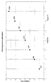
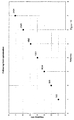
- Figure 7 graphically shows the frequency ratios of the first 7 frequencies in the frequency sequence for the initial bell shape.
- the absolute frequencies (as opposed to frequency ratios) in Hertz are listed adjacent their respective points on the graph.
- the magnitude of the fifth frequency was constrained at 1702 Hz and the seventh frequency was made the objective function with an objective of 2434 Hz.
- the tolerance on the constraint was not changed.
- the first seven frequencies are all due to (m,0) modes. That is, the first seven modes are (2,0), (3,0), (4,0), (5,0), (6,0), (7,0), and (8,0).
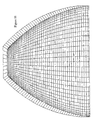
- Table 2 provides a list of the coordinates (in cartesian/rectangular coordinates) of the nodes shown in Figure 11 to define the shape of the inner surface of the bell.
- the origin of the coordinates is shown in Figure 11 and is located on the axis of symmetry about a quarter of the height of the bell above the mouth of the bell.
- Table 3 provides a list of the coordinates of the three points that together define the curved part of the outer surface of the side portion.
- the curved part of the outer surface is defined by fitting the arc of a circle to the three points.
- the additional cylindrical part of the outer surface of the side portion is formed by continuing the bottom of curve defined in Table 3 to the point (125.2,-38.4).
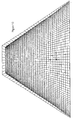
- Figure 12 provides a further example of an harmonic bell designed in accordance with the present invention.
- Table 4 shows the frequencies and frequency ratios of the first seven frequencies in the frequency sequence.
- the first seven frequencies are all due to (m,0) modes. That is, the first seven modes are (2,0), (3,0), (4,0), (5,0), (6,0), (7,0), and (8,0).
- Table 5 provides a list of the coordinates of the nodes that together define the inner surface of the side portion.
- Table 6 provides the two points which, when joined by a straight line, defines the shape of the outer surface of the side portion.
- Frequency 1 1 2 2 3 3 4 4 5 5 6 6 7 7 freq ratio freq ratio freq ratio freq ratio freq ratio freq ratio freq ratio freq ratio freq ratio Final shape 186 1 375 2.016 556 2.989 739 3.973 919 4.941 1121 6.027 1300 6.989 Error 0.008 0.000 -0.01 -0.01 0.004 0.000 Node x y Node x y Node x y Node x y 1 196.6 -49.9 12 139.9 36 23 85.4 124.6 2 191.5 -40.9 13 135.1 45 24 80.4 132.4 3 186.3 -33 14 130.2 536 25 75.3 140.3 4 181 -25.3 15 125.3 61.1 26 70.3
- the outer surface was constrained and thus remains identical to the outer surface of the initial shape used in the optimisation procedure.
- the inner surface could have been constrained instead, in which case the inner surface would remain identical to the inner surface of the initial shape.
Landscapes
- Physics & Mathematics (AREA)
- Engineering & Computer Science (AREA)
- Acoustics & Sound (AREA)
- Multimedia (AREA)
- Main Body Construction Of Washing Machines And Laundry Dryers (AREA)
- Electrophonic Musical Instruments (AREA)
- Electrical Discharge Machining, Electrochemical Machining, And Combined Machining (AREA)
- Auxiliary Devices For Music (AREA)
- Electromechanical Clocks (AREA)
Applications Claiming Priority (2)
| Application Number | Priority Date | Filing Date | Title |
|---|---|---|---|
| AUPQ361399 | 1999-10-22 | ||
| AUPQ3613A AUPQ361399A0 (en) | 1999-10-22 | 1999-10-22 | Improvements in or relating to bells |
Publications (2)
| Publication Number | Publication Date |
|---|---|
| EP1120773A2 true EP1120773A2 (de) | 2001-08-01 |
| EP1120773A3 EP1120773A3 (de) | 2003-11-05 |
Family
ID=3817764
Family Applications (1)
| Application Number | Title | Priority Date | Filing Date |
|---|---|---|---|
| EP00420214A Withdrawn EP1120773A3 (de) | 1999-10-22 | 2000-10-20 | Verbesserungen in oder bezüglich zu Glocken |
Country Status (3)
| Country | Link |
|---|---|
| US (1) | US6915756B1 (de) |
| EP (1) | EP1120773A3 (de) |
| AU (1) | AUPQ361399A0 (de) |
Cited By (1)
| Publication number | Priority date | Publication date | Assignee | Title |
|---|---|---|---|---|
| GB2578319A (en) * | 2018-10-23 | 2020-05-06 | John Taylor Bell Foundry Loughborough Ltd | A bell and a method of designing a bell |
Families Citing this family (4)
| Publication number | Priority date | Publication date | Assignee | Title |
|---|---|---|---|---|
| US7750218B2 (en) * | 2006-07-18 | 2010-07-06 | John Stannard | Vibrato based percussion instrument |
| KR100889495B1 (ko) * | 2007-08-20 | 2009-03-19 | 재단법인서울대학교산학협력재단 | 미세 비대칭 링 구조물의 맥놀이 조율 방법 |
| WO2011067730A1 (en) * | 2009-12-02 | 2011-06-09 | The University Of Melbourne | Bells and methods of their design and production |
| US10424278B2 (en) * | 2017-08-02 | 2019-09-24 | Applied Invention, Llc | Bell with subharmonic difference tone |
Family Cites Families (6)
| Publication number | Priority date | Publication date | Assignee | Title |
|---|---|---|---|---|
| US296515A (en) * | 1884-04-08 | bowees | ||
| GB1258770A (de) * | 1969-03-28 | 1971-12-30 | ||
| US3760482A (en) * | 1972-05-18 | 1973-09-25 | Suwa Seikosha Kk | Method of adjusting frequency of tuning fork type vibrator |
| US3871094A (en) * | 1974-04-26 | 1975-03-18 | Norlin Music Inc | Method of making seamless tubular bell section |
| JPH0792670B2 (ja) * | 1989-11-11 | 1995-10-09 | ナカシマプロペラ株式会社 | ベルの設計方法およびこの方法によって得られるベル |
| JP2871282B2 (ja) * | 1992-04-14 | 1999-03-17 | 三菱重工業株式会社 | 定肉厚鐘体 |
-
1999
- 1999-10-22 AU AUPQ3613A patent/AUPQ361399A0/en not_active Abandoned
-
2000
- 2000-10-18 US US09/691,583 patent/US6915756B1/en not_active Expired - Lifetime
- 2000-10-20 EP EP00420214A patent/EP1120773A3/de not_active Withdrawn
Non-Patent Citations (2)
| Title |
|---|
| FLETCHER N H: "Tuning a pentangle-a new musical vibrating element" APPLIED ACOUSTICS, 1993, UK, vol. 39, no. 3, pages 145-163, XP001132055 ISSN: 0003-682X * |
| ROSSING T D: "Acoustics of eastern and western bells, old and new" J. ACOUST. SOC. JPN. (E) (JAPAN), JOURNAL OF THE ACOUSTICAL SOCIETY OF JAPAN (E), SEPT. 1989, JAPAN, vol. 10, no. 5, pages 241-252, XP001132056 ISSN: 0388-2861 * |
Cited By (3)
| Publication number | Priority date | Publication date | Assignee | Title |
|---|---|---|---|---|
| GB2578319A (en) * | 2018-10-23 | 2020-05-06 | John Taylor Bell Foundry Loughborough Ltd | A bell and a method of designing a bell |
| US10777182B2 (en) | 2018-10-23 | 2020-09-15 | John Taylor Bell Foundry (Loughborough) Limited | Bell and a method of designing a bell |
| GB2578319B (en) * | 2018-10-23 | 2023-05-24 | John Taylor Bell Foundry Loughborough Ltd | A bell and a method of designing a bell |
Also Published As
| Publication number | Publication date |
|---|---|
| US6915756B1 (en) | 2005-07-12 |
| AUPQ361399A0 (en) | 1999-11-18 |
| EP1120773A3 (de) | 2003-11-05 |
Similar Documents
| Publication | Publication Date | Title |
|---|---|---|
| JP5877230B2 (ja) | タイヤノイズピッチ列の設計方法 | |
| Arnold et al. | Flexural vibrations of the walls of thin cylindrical shells having freely supported ends | |
| AU2007352137B2 (en) | The G-Pan musical instrument | |
| US7376553B2 (en) | Fractal harmonic overtone mapping of speech and musical sounds | |
| MX2010012261A (es) | Proguanil para tratar enfermedades de la piel/mucosa. | |
| US6915756B1 (en) | Bells | |
| US4273020A (en) | Method of constructing trumpet or other brass instrument | |
| Kausel | Optimization of brasswind instruments and its application in bore reconstruction | |
| US5950152A (en) | Method of changing a pitch of a VCV phoneme-chain waveform and apparatus of synthesizing a sound from a series of VCV phoneme-chain waveforms | |
| AU6661600A (en) | Improvements in or relating to bells | |
| US6008443A (en) | Enhancements introduced into brass instruments and method for the manufacturing of parts for such instruments | |
| Samejima et al. | Vibration analysis of a musical drum head under nonuniform density and tension using a spectral method | |
| Weltevrede et al. | Refraction in a pulsar magnetosphere–the effect of a variable emission height on pulse morphology | |
| Murr et al. | Materials science and metallurgy of the Caribbean steel drum Part I Fabrication, deformation phenomena and acoustic fundamentals | |
| Hartmann et al. | Periodic signals with minimal power fluctuations | |
| US20120304846A1 (en) | Bells and methods of their design and production | |
| Nigjeh et al. | Application of modal analysis to musical bell design | |
| TWI620169B (zh) | 具簡諧倍頻音之銅鐘的設計方法及其銅鐘 | |
| CN110840482B (zh) | 超音波成像系统及其方法 | |
| US3683845A (en) | Domes for electric bells | |
| Kmsel et al. | A Computer Program for Brass Instrument Optimization Part I. Concept and Implementation | |
| Kausel | Computer optimization of brass wind instruments | |
| Smolen et al. | A Method for Three-Dimensional Horn Geometry Optimization | |
| JP2755478B2 (ja) | テキスト音声合成装置 | |
| Thomas et al. | Tonal optimization of bells utilizing evolutionary shape optimization |
Legal Events
| Date | Code | Title | Description |
|---|---|---|---|
| PUAI | Public reference made under article 153(3) epc to a published international application that has entered the european phase |
Free format text: ORIGINAL CODE: 0009012 |
|
| AK | Designated contracting states |
Kind code of ref document: A2 Designated state(s): AT BE CH CY DE DK ES FI FR GB GR IE IT LI LU MC NL PT SE |
|
| AX | Request for extension of the european patent |
Free format text: AL;LT;LV;MK;RO;SI |
|
| PUAL | Search report despatched |
Free format text: ORIGINAL CODE: 0009013 |
|
| AK | Designated contracting states |
Kind code of ref document: A3 Designated state(s): AT BE CH CY DE DK ES FI FR GB GR IE IT LI LU MC NL PT SE |
|
| AX | Request for extension of the european patent |
Extension state: AL LT LV MK RO SI |
|
| AKX | Designation fees paid | ||
| REG | Reference to a national code |
Ref country code: DE Ref legal event code: 8566 |
|
| 17P | Request for examination filed |
Effective date: 20040709 |
|
| RBV | Designated contracting states (corrected) |
Designated state(s): FR GB NL |
|
| RBV | Designated contracting states (corrected) |
Designated state(s): FR GB NL |
|
| 17Q | First examination report despatched |
Effective date: 20050609 |
|
| STAA | Information on the status of an ep patent application or granted ep patent |
Free format text: STATUS: THE APPLICATION IS DEEMED TO BE WITHDRAWN |
|
| 18D | Application deemed to be withdrawn |
Effective date: 20051020 |