EP1120545B1 - Locking device for rotorblades in axial turbines - Google Patents
Locking device for rotorblades in axial turbines Download PDFInfo
- Publication number
- EP1120545B1 EP1120545B1 EP00118862A EP00118862A EP1120545B1 EP 1120545 B1 EP1120545 B1 EP 1120545B1 EP 00118862 A EP00118862 A EP 00118862A EP 00118862 A EP00118862 A EP 00118862A EP 1120545 B1 EP1120545 B1 EP 1120545B1
- Authority
- EP
- European Patent Office
- Prior art keywords
- retaining ring
- blade root
- locking device
- blade
- accordance
- Prior art date
- Legal status (The legal status is an assumption and is not a legal conclusion. Google has not performed a legal analysis and makes no representation as to the accuracy of the status listed.)
- Expired - Lifetime
Links
Images


Classifications
-
- F—MECHANICAL ENGINEERING; LIGHTING; HEATING; WEAPONS; BLASTING
- F01—MACHINES OR ENGINES IN GENERAL; ENGINE PLANTS IN GENERAL; STEAM ENGINES
- F01D—NON-POSITIVE DISPLACEMENT MACHINES OR ENGINES, e.g. STEAM TURBINES
- F01D5/00—Blades; Blade-carrying members; Heating, heat-insulating, cooling or antivibration means on the blades or the members
- F01D5/30—Fixing blades to rotors; Blade roots ; Blade spacers
- F01D5/32—Locking, e.g. by final locking blades or keys
- F01D5/326—Locking of axial insertion type blades by other means
-
- F—MECHANICAL ENGINEERING; LIGHTING; HEATING; WEAPONS; BLASTING
- F01—MACHINES OR ENGINES IN GENERAL; ENGINE PLANTS IN GENERAL; STEAM ENGINES
- F01D—NON-POSITIVE DISPLACEMENT MACHINES OR ENGINES, e.g. STEAM TURBINES
- F01D5/00—Blades; Blade-carrying members; Heating, heat-insulating, cooling or antivibration means on the blades or the members
- F01D5/30—Fixing blades to rotors; Blade roots ; Blade spacers
- F01D5/3007—Fixing blades to rotors; Blade roots ; Blade spacers of axial insertion type
- F01D5/3015—Fixing blades to rotors; Blade roots ; Blade spacers of axial insertion type with side plates
Definitions
- the invention relates to a retaining device for rotor blades of an axial turbomachine according to the preamble of patent claim 1.
- the blades of a turbine stage are generally anchored in recesses provided for this purpose on the circumference of a rotor disk.
- the blade feet for example, droplet-shaped or dovetail-shaped, so that the individual blades can be easily axially push into corresponding recesses on the circumference of the rotor disk. Due to the tapering of the blade feet, the individual blades are held in the radial direction in the rotor disk. In order to avoid a displacement of the blades in the axial direction, they can be locked, for example by a grub screw in its anchorage. In other retention mechanisms clamping pins are provided to provide a corresponding locking in the axial direction.
- a further known from the prior art retaining device has for receiving the rotor blades on the circumference of a rotor disk fir-tooth-like toothed recesses.
- corresponding blade feet also provided with a fir tree-like toothing are inserted axially.
- the blade root holder is slightly conical in the axial direction, so that the blade can be inserted and removed only in one direction.
- the blade root is fixed in this prior art by holding plates in its positions.
- Such retaining plates are for example described in EP 0761930 A1.
- Such holding plates are expensive to manufacture and require special tools during assembly. Due to the high mass of the holding plates high centrifugal forces are generated.
- US 4,846,628 proposes a closed, circumferential holding and sealing ring, which has elevations on its inner circumference, which engage in corresponding claws of the rotor disk.
- This holding and sealing ring covers the entire blade root height and has a labyrinth seal on its outer circumference. Furthermore, the holding and sealing ring described here and the blade feet must be positioned exactly in the axial direction to each other, so that the holding and sealing ring circumferentially formed contact seal can act.
- FIG. 90 A similar prior art retaining and sealing ring 90 is shown in FIG.
- the assembly and locking takes place in this prior art in a manner similar to a bayonet lock. Since the holding and sealing ring used at the same time serves as a seal against leakage flows between the rotor 93 and blades 94, it covers virtually the entire blade root 91 and must be manufactured and mounted due to the circumferential contact seal 92 with great accuracy. Furthermore, this holding and sealing ring 90 on its outer circumference on a labyrinth seal 95.
- EP 0463955 B1 shows in the context of an embodiment, a circumferential retaining ring for a rotor blading, which covers most of the blade root. Structure and operation of this retaining ring is not described further in this prior art.
- GB 2 258 273 A which forms the closest prior art, describes a retaining device in which the rotor disk has a groove which opens radially inwardly and in which the blade root is provided with a groove which opens radially outwards.
- the retaining ring can be inserted between these two grooves.
- the retaining ring is double-walled in its retention area by a loop-like part of the retaining ring is bent upwards and acts resiliently. This results on the one hand, due to the elasticity of the bent-up part, problems with the game occurring, on the other hand, such a retaining ring is costly and expensive to install.
- EP 0 833 039 A This publication shows a retaining ring with raised sections and recesses.
- the present invention is therefore an object of the invention to provide a retainer for blades of a turbomachine, which avoids the disadvantages of the prior art.
- this is to provide a cost-effective restraint device which enables the improved control of leakage flows in the blade root area, overall improved flow conditions in the interstage area, lower centrifugal forces and easy installation.
- the device according to the invention with the features of claim 1 has the advantage that a cost-effective retainer for blades of an axial turbomachine is provided which allows an improved control of leaks in the blade root area, overall improved flow conditions in the interstage area, lower centrifugal forces and easy installation.
- This is achieved by the separation of the retention function, which is fulfilled by the retaining ring according to the invention, and the sealing function, which is fulfilled by using a retaining ring according to the invention by corresponding sealing surfaces between the blade and rotor disk, a considerable statisticserspamis.
- the retaining function is fulfilled by arranged on the outer periphery of the retaining ring raised portions which cooperate with corresponding blade root sections. The directions given below are based on the rotor disk as a reference system.
- the raised portions formed on the outer circumference of the retaining ring can be formed either according to claim 2 or according to claim 4.
- the corresponding blade root portions are formed according to claim 3 or according to claim 5.
- the raised portion on the outer circumference of the retaining ring from the side inserted into a corresponding receptacle on the blade root.
- Complex special tool can be dispensed with in the present invention, since the retaining ring can be easily assembled with the usual assembly tools.
- the invention thus provides a locking mechanism for the retaining ring which acts in a manner similar to a bayonet closure.
- a significant weight saving is associated, which reduces both the manufacturing costs and the centrifugal forces and thereby enables higher speeds. Furthermore, due to the low blade root overlap, flow channels in the blade root area become possible which positively influence the flow and cooling air ratios between the rotor stages while penetrating the blade root area.
- an embodiment is provided as a blocking block, which is inserted between two jaws of the locking mechanism.
- the block can be secured, for example by securing wires against accidental slipping out.
- several of these locks are provided on a rotor stage for redundancy reasons.
- the design of the Schaufelfuß technique according to the features of claim 10 is particularly advantageous.
- a fir-tree-like configuration of the toothing, which tapers conically in the axial direction, is advantageous.
- the restraint device described is otherwise suitable for compressor and turbine stages. Particularly advantageous is a use in a turbine stage.
- FIG. 1 is a schematic sectional view of the retaining device, in which a section of a rotor disk 2 is shown in section.
- a blade 4 also shown in fragmentary form.
- the blade 4 is received via a blade root 3 in a formed on the outer periphery of the turbine disk 2 Schaufelfuß technique 12 and thereby fixed in the radial direction.
- the blade 4 is secured by a retaining ring 1.
- a arranged in the region of the blade root 3 flow channel 14 is shown in dashed lines, which contributes to the improvement of the interstage flow.
- a corresponding flow channel 14 is substantially possible by the inventive design of the retaining ring 1, which covers less than a third, in the present case about one-eighth of the blade root height.
- the outlet opening 16 of the flow channel 14 is free, so that cooling air from the flow channel 14 can freely enter the disc space 2 following the disc rotor.
- retention and sealing function are decoupled from each other.
- the sealing function is perceived by a blade / disc sealing surface 15 to avoid leakage.
- the blade / disc sealing surface 15 is formed as a mating surface between the bottom 26 of the blade platform and the top of the disposed between the Schaufelfußfactn 12 disc posts 25.
- the closed, circumferential has on its inner circumference inwardly projecting portions 20 which engage in protruding on the rotor disk 2 claws
- the claws 21 are on the one hand from a vertically projecting from the turbine disk 2, but thereby interrupted in the circumferential direction (see Fig. 3) rail 6 and on the other from a parallel to the turbine disk 2 arranged (of course also not circulating - see again Fig .3) stop 9 are formed and are thus arranged at regular intervals on the circumference of the rotor disk 2.
- the rotor disk 2 in this case has below the Schaufelfußability 12 a circumferential recess 23 (viewed in the axial direction), which is continued at its lower end as (while interrupted) rail 6. At its upper end, the recess 23 has a machined guide surface 27, which corresponds to a shoulder 22 of the retaining ring 1.
- the radially inwardly projecting portions 20 and the claws 21 act like a bayonet lock together.
- the retaining ring 1 is shown in detail in FIG. In the area of the outer circumference, the retaining ring 1 has the stepped shoulder 22 already mentioned above. This forms with the machined surface 27 of the recess 23 a guide for the retaining ring 1 and thereby allows the precise insertion of arranged on the outer periphery of the retaining ring 1 raised portions 17 in a groove or retaining groove 5 a protruding retaining lug 18 of the blade 4.
- Further 2 shows a locking device 8 for fixing the retaining ring 1 in the circumferential direction.
- the arresting device 8 is formed by a substantially block-shaped block which can be inserted into the recesses formed on the inner circumference of the retaining ring 1 between the protruding portions 20.
- the locking device 8 is secured against displacement in the axial direction by locking wires 10, which are respectively passed through holes 24 at the two ends of the locking device 8, as the perspective view in Figure 6 can be removed.
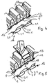
- the basic structure of the retaining ring 1 is clearer by the fragmentary view in Figure 3.
- the retaining ring 1 is first, as shown in perspective in Figure 3, applied to the rotor disk 2.
- the radially inwardly projecting from the retaining ring 1 sections 20 are each between two jaws 21 of the rotor disk 2.
- the blade foot 12 formed on the outer circumference of the rotor disk 2 in this case have a fir-tree-like teeth 13.
- the retaining ring 1 in the circumferential direction moved so that the Schaufelfuß techniquen 12 are completely released.
- the radially inwardly projecting portions 20 on the inner circumference of the retaining ring 1 partially slide into the claws 21 on the rotor disk 2.
- the blade 4 is then inserted into the blade root receiver 12, as shown by way of example for a blade in FIG.
- the blade 4 in the region of the blade root 3 a retaining lug 18 with the retaining groove 5 shown in Figures 1 and 2 on.
- the raised portions 17 arranged on the outer circumference of the retaining ring 1 are inserted into the corresponding retaining grooves 5.
- the blades 4 are axially fixed in the Schaufelfußing techniquen 12.
- the outlet opening 16 of the flow channel shown in FIG. 1 is provided or shown on the retaining lug 18.
- the blade 4 After inserting the lock 8 and securing it by securing wires 10, the blade 4 is secured and ready for operation with the rotor disk 2, as shown by way of example with reference to a blade in Figure 6.
- FIG. 7 shows a second embodiment of the present invention.
- the same or similar parts are provided with the same reference numerals.
- raised portions 17 are formed like a sawtooth.
- the sawtooth-like raised portions 17 can be inserted laterally into recesses 28 provided thereon on the blade root 3, as indicated schematically in FIG.
- FIG. 7 also shows the blade / disk sealing surfaces 15, which perform the function of the contact seal 91 of the prior art shown in FIG.
- FIG. 8 shows a view of the retaining ring 1 provided with sawtooth-like raised portions 17.
- the mounting of the retaining ring 1 takes place in an analogous manner as described with reference to FIGS. 1 to 6.
- the radially inwardly projecting from the retaining ring 1 sections 20 are each between two jaws 21 of the rotor disk 2.
- the blade foot 12 formed on the outer circumference of the rotor disk 2 in this case have a fir-tree-like teeth 13.
- a locking device (not shown) is inserted into the recesses between the inwardly protruding portions 20 for locking the retaining ring 1.
Description
Die Erfindung betrifft eine Rückhaltevorrichtung für Rotorschaufeln einer Axialturbomaschine gemäß dem Oberbegriff des Patentanspruchs 1.The invention relates to a retaining device for rotor blades of an axial turbomachine according to the preamble of
Aus dem Stand der Technik sind verschiedene Rückhaltemechanismen für Laufschaufeln einer Axialturbomaschine bekannt. So werden die Schaufeln einer Turbinenstufe im allgemeinen in hierfür vorgesehene Vertiefungen am Umfang einer Rotorscheibe verankert. Dabei sind die Schaufelfüße beispielsweise tropfenförmig oder schwalbenschwanzartig ausgestaltet, so daß sich die einzelnen Schaufeln leicht axial in korrespondierende Vertiefungen am Umfang der Rotorscheibe hineinschieben lassen. Durch die Verjüngung der Schaufelfüße werden die einzelnen Schaufeln in radialer Richtung in der Rotorscheibe gehalten. Um eine Verschiebung der Schaufeln in axialer Richtung zu vermeiden, können diese beispielsweise durch eine Madenschraube in ihrer Verankerung arretiert werden. Bei anderen Rückhaltemechanismen werden Klemmzapfen vorgesehen, um eine entsprechende Arretierung in axialer Richtung zu schaffen.Various restraining mechanisms for moving blades of an axial turbomachine are known from the prior art. Thus, the blades of a turbine stage are generally anchored in recesses provided for this purpose on the circumference of a rotor disk. In this case, the blade feet, for example, droplet-shaped or dovetail-shaped, so that the individual blades can be easily axially push into corresponding recesses on the circumference of the rotor disk. Due to the tapering of the blade feet, the individual blades are held in the radial direction in the rotor disk. In order to avoid a displacement of the blades in the axial direction, they can be locked, for example by a grub screw in its anchorage. In other retention mechanisms clamping pins are provided to provide a corresponding locking in the axial direction.
Eine weitere aus dem Stand der Technik bekannte Rückhaltevorrichtung weist zur Aufnahme der Rotorschaufeln am Umfang einer Rotorscheibe tannenbaumartig verzahnte Vertiefungen auf. Hierin werden korrespondierende ebenfalls mit einer tannenbaumartigen Verzahnung versehene Schaufelfüße axial eingeschoben. Dabei ist die Schaufelfußhalterung in axialer Richtung leicht konisch ausgeführt, so daß die Schaufel jeweils nur in einer Richtung eingeschoben und entnommen werden kann. Um ein unbeabsichtigtes Lösen und Herausrutschen der Schaufel aus der Schaufelfußhalterung zu vermeiden, wird der Schaufelfuß bei diesem Stand der Technik durch Halteplatten in seiner Positionen fixiert. Derartige Halteplatten sind beispielsweise in der EP 0761930 A1 beschrieben. Derartige Halteplatten sind kostspielig in der Herstellung und erfordern spezielle Werkzeuge bei der Montage. Aufgrund der hohen Masse der Halteplatten werden hohe Fliehkräfte erzeugt.A further known from the prior art retaining device has for receiving the rotor blades on the circumference of a rotor disk fir-tooth-like toothed recesses. Herein, corresponding blade feet also provided with a fir tree-like toothing are inserted axially. The blade root holder is slightly conical in the axial direction, so that the blade can be inserted and removed only in one direction. In order to avoid accidental loosening and slipping out of the blade from the Schaufelfußhalterung, the blade root is fixed in this prior art by holding plates in its positions. Such retaining plates are for example described in EP 0761930 A1. Such holding plates are expensive to manufacture and require special tools during assembly. Due to the high mass of the holding plates high centrifugal forces are generated.
Um die Strömungsverhältnisse zwischen den einzelnen Schaufelstufen zu verbessern, schlägt die US 4,846,628 einen geschlossenen, umlaufenden Halte- und Dichtungsring vor, der an seinem Innenumfang Erhebungen aufweist, die in entsprechende Klauen der Rotorscheibe eingreifen. Dieser Halte- und Dichtungsring überdeckt die gesamte Schaufelfußhöhe und weist an seinem Außenumfang eine Labyrinthdichtung auf. Ferner müssen der hier beschriebene Halte- und Dichtungsring und die Schaufelfüße exakt in axialer Richtung zueinander positioniert sein, damit die am Halte- und Dichtungsring umlaufend ausgebildete Berührungsdichtung wirken kann.In order to improve the flow conditions between the individual blade stages, US 4,846,628 proposes a closed, circumferential holding and sealing ring, which has elevations on its inner circumference, which engage in corresponding claws of the rotor disk. This holding and sealing ring covers the entire blade root height and has a labyrinth seal on its outer circumference. Furthermore, the holding and sealing ring described here and the blade feet must be positioned exactly in the axial direction to each other, so that the holding and sealing ring circumferentially formed contact seal can act.
Ein ähnlicher Halte- und Dichtungsring 90 vom Stand der Technik ist in Figur 9 dargestellt. Die Montage und Arretierung erfolgt bei diesem Stand der Technik in einer Weise ähnlich einem Bajonettverschluß. Da der dabei verwendete Halte- und Dichtungsring gleichzeitig als Dichtung gegen Leckströmungen zwischen Rotor 93 und Schaufeln 94 dient, deckt er quasi den gesamten Schaufelfuß 91 ab und muß aufgrund der umlaufenden Berührungsdichtung 92 mit großer Genauigkeit gefertigt und montiert werden. Ferner weist dieser Halte- und Dichtungsring 90 an seinem Außenumfang eine Labyrinthdichtung 95 auf.A similar prior art retaining and
Die beiden zuletzt beschriebenen Halte- und Dichtungsvorrichtungen haben den Nachteil, daß sie aufgrund der geringen Toleranzen bei Herstellung und Montage sehr teuer sind. Aufgrund der hohen Masse sind die damit erzielbaren Drehzahlen bzw. die Lebensdauer eingeschränkt.The last two holding and sealing devices described have the disadvantage that they are very expensive due to the small tolerances in manufacture and assembly. Due to the high mass achievable speeds or life are limited.
Zwar zeigt die EP 0463955 B1 im Rahmen eines Ausführungsbeispiels einen umlaufenden Rückhaltering für eine Rotorbeschaufelung, der den größten Teil des Schaufelfußes überdeckt. Aufbau und Funktionsweise dieses Rückhalterings wird jedoch bei diesem Stand der Technik nicht weiter beschrieben.Although EP 0463955 B1 shows in the context of an embodiment, a circumferential retaining ring for a rotor blading, which covers most of the blade root. Structure and operation of this retaining ring is not described further in this prior art.
In der den nächstkommenden Stand der Technik bildenden GB 2 258 273 A ist eine Rückhaltevorrichtung beschrieben, bei welcher die Rotorscheibe eine radial nach innen gerichtet offene Nut aufweist und bei welcher der Schaufelfuß mit einer radial nach außen gerichtet geöffneten Nut versehen ist. Zwischen diese beiden Nuten ist der Rückhaltering einschiebbar. Der Rückhaltering ist dabei in seinem Rückhaltebereich doppelwandig ausgebildet, indem ein schlaufenartiger Teil des Rückhalterings nach oben gebogen ist und federnd wirkt. Hierdurch ergeben sich zum einen, bedingt durch die Elastizität des hochgebogenen Teils, Probleme mit dem auftretenden Spiel, zum anderen ist ein derartiger Haltering kostenintensiv und aufwendig in der Montage.
US 5,330,324 A: Diese Druckschrift beschreibt eine ähnliche Konstruktion, wie die oben genannte GB 2 258 273 A.US 5,330,324 A: This document describes a similar construction to the
EP 0 833 039 A: Diese Veröffentlichung zeigt einen Haltering mit erhabenen Abschnitten sowie Aussparungen.EP 0 833 039 A: This publication shows a retaining ring with raised sections and recesses.
Der vorliegenden Erfindung liegt daher die Aufgabe zugrunde, eine Rückhaltevorrichtung für Laufschaufeln einer Turbomaschine zu schaffen, welche die Nachteile des Standes der Technik vermeidet. Außerdem soll hierdurch eine kostengünstige Rückhaltevorrichtung zur Verfügung gestellt werden, welche die verbesserte Beherrschung von Leckströmungen im Schaufelfußbereich, insgesamt verbesserte Strömungsbedingungen im Zwischenstufenbereich, geringere Fliehkräfte und eine leichte Montage ermöglicht.The present invention is therefore an object of the invention to provide a retainer for blades of a turbomachine, which avoids the disadvantages of the prior art. In addition, this is to provide a cost-effective restraint device which enables the improved control of leakage flows in the blade root area, overall improved flow conditions in the interstage area, lower centrifugal forces and easy installation.
Diese Aufgabe wird durch eine Rückhaltevorrichtung mit den Merkmalen des Patentanspruchs 1 gelöst. Vorteilhafte Ausgestaltungen der Erfindung werden in den Unteransprüchen beschrieben.This object is achieved by a retaining device having the features of
Die erfindungsgemäße Vorrichtung mit den Merkmalen des Patentanspruchs 1 hat den Vorteil, daß eine kostengünstige Rückhaltevorrichtung für Laufschaufeln einer Axialturbomaschine zur Verfügung gestellt wird, die eine verbesserte Beherrschung von Leckströmungen im Schaufelfußbereich, insgesamt verbesserte Strömungsbedingungen im Zwischenstufenbereich, geringere Fliehkräfte und eine leichte Montage ermöglicht. Dabei wird durch die Trennung der Rückhaltefunktion, die vom erfindungsgemäßen Rückhaltering erfüllt wird, und der Dichtungsfunktion, die bei Verwendung eines erfindungsgemäßen Rückhalterings durch entsprechende Dichtflächen zwischen Schaufel und Rotorscheibe erfüllt wird, eine erhebliche Gewichtserspamis erzielt. Außerdem sind aufgrund des Wegfalls von Berührungs- und Labyrinthdichtungen größere Fertigungs- und Montagetoleranzen möglich. Die Rückhaltefunktion wird dabei durch am Außenumfang des Rückhalterings angeordnete erhabene Abschnitte erfüllt, die mit korrespondierenden Schaufelfußabschnitten zusammenwirken. Die im folgenden verwendeten Richtungsangaben gehen von der Rotorscheibe als Bezugssystem aus.The device according to the invention with the features of
Nach alternativen Weiterbildungen können die am Außenumfang des Rückhalterings gebildeten erhabenen Abschnitte entweder gemäß Anspruch 2 oder gemäß Anspruch 4 ausgebildet sein. Je nach Ausgestaltung der erhabenen Abschnitte sind die korrespondierenden Schaufelfußabschnitte gemäß Anspruch 3 oder gemäß Anspruch 5 ausgebildet. Im Unterschied zur Ausführungsform nach Anspruch 2 und 3 wird bei der Ausgestaltung nach Anspruch 4 und 5 der erhabene Abschnitt am Au-ßenumfang des Rückhalterings von der Seite in eine entsprechende Aufnahme am Schaufelfuß eingeschoben. Auf aufwendiges Spezialwerkzeug kann bei der vorliegenden Erfindung verzichtet werden, da sich der Rückhaltering leicht mit den gängigen Montagewerkzeugen montieren lässt.According to alternative developments, the raised portions formed on the outer circumference of the retaining ring can be formed either according to
Die Erfindung sieht somit einen in ähnlicher Weise wie ein Bajonettverschluss wirkenden Verriegelungsmechanismus für den Rückhaltering vor.The invention thus provides a locking mechanism for the retaining ring which acts in a manner similar to a bayonet closure.
Erfindungsgemäß ist eine erhebliche Gewichtseinsparung verbunden, die sowohl die Herstellungskosten als auch die Fliehkräfte verringert und die dadurch höhere Drehzahlen ermöglicht. Ferner werden durch die geringe Schaufelfußüberdeckung Strömungskanäle im Schaufelfußbereich möglich, die unter Durchdringung des Schaufelfußbereiches die Strömungs- und Kühlluftverhältnisse zwischen den Rotorstufen positiv beeinflussen.According to the invention, a significant weight saving is associated, which reduces both the manufacturing costs and the centrifugal forces and thereby enables higher speeds. Furthermore, due to the low blade root overlap, flow channels in the blade root area become possible which positively influence the flow and cooling air ratios between the rotor stages while penetrating the blade root area.
Erfind.ungsgemäß ist eine Ausgestaltung als Sperrklotz vorgesehen, der zwischen zwei Klauen des Verriegelungsmechanismus eingeschoben wird. Der Sperrklotz kann dabei beispielsweise durch Sicherungsdrähte gegen unbeabsichtigtes Herausgleiten gesichert werden. Im Normalfall sind aus Redundanzgründen mehrere dieser Arretierungen an einer Rotorstufe vorgesehen.According to the invention, an embodiment is provided as a blocking block, which is inserted between two jaws of the locking mechanism. The block can be secured, for example by securing wires against accidental slipping out. In the normal case, several of these locks are provided on a rotor stage for redundancy reasons.
Durch die Ausgestaltung der Schaufel/Scheibe Dichtfläche gemäß Anspruch 9 sind keine zusätzlichen Dichtungen am erfindungsgemäßen Rückhaltering vorzusehen. Die Herstellung der Dichtflächen an der Unterseite der Schaufelplattform und den Rotorpfosten verlangt keinen zusätzlichen Arbeitsschritt, da sie bei der spanenden Nachbearbeitung der entsprechenden Bauteile mit erfolgen kann. Ungenauigkeiten bei der axialen Positionierung der Schaufeln beeinträchtigen bei dieser Ausführungsform das Dichtungsverhalten nicht.Due to the design of the blade / disc sealing surface according to claim 9, no additional seals on the retaining ring according to the invention are provided. The preparation of the sealing surfaces on the underside of the blade platform and the rotor post requires no additional step, since it can be done during the machining of the corresponding components with. Inaccuracies in the axial positioning of the blades do not affect the sealing behavior in this embodiment.
Die Gestaltung der Schaufelfußaufnahme gemäß den Merkmalen des Patentanspruchs 10 ist besonders vorteilhaft. Insbesondere ist dabei eine tannenbaumartige Ausbildung der Verzahnung, die sich in axialer Richtung konisch verjüngt, vorteilhaft. Die beschriebene Rückhaltevorrichtung ist im übrigen für Verdichter- und Turbinenstufen geeignet. Besonders vorteilhaft ist dabei eine Verwendung in einer Turbinenstufe.The design of the Schaufelfußaufnahme according to the features of claim 10 is particularly advantageous. In particular, a fir-tree-like configuration of the toothing, which tapers conically in the axial direction, is advantageous. The restraint device described is otherwise suitable for compressor and turbine stages. Particularly advantageous is a use in a turbine stage.
Weitere Ausgestaltungen und Vorteile der Erfindung werden durch die Beschreibung der Ausführungsbeispiele unter Bezugnahme auf die beigefügten Zeichnungen läutert. Darin zeigen:
Figur 1- eine schematische Schnittansicht einer vorteilhaften Ausführungsform der vorliegenden Erfindung;
Figur 2- eine Detailansicht der erfindungsgemäßen Rückhaltevorrichtung gemäß der Ausführungsform aus
Figur 1; Figur 3- eine perspektivische Ansicht der vorliegenden Erfindung gemäß der Ausführungsform nach
Figur 1 in einem ersten Montageschritt; Figur 4- eine zweite perspektivische Ansicht der vorliegenden Erfindung gemäß der Ausführungsform nach
Figur 1 in einem zweiten Montageschritt; Figur 5- eine dritte perspektivische Ansicht der vorliegenden Erfindung gemäß der Ausführungsform nach Figur 1 in einem dritten Montageschritt;
Figur 6- eine vierte perspektivische Ansicht der vorliegenden Erfindung gemäß der Ausführungsform nach Figur 1 im fertig montierten Zustand;
Figur 7- eine zweite vorteilhafte Ausführungsform der vorliegenden Erfindung, in einen Ausschnitt, bei dem der Rückhaltering sägezahnförmige Erhebungen aufweist;
Figur 8- eine schematische Ansicht der zweiten Ausführungsform der vorliegenden Erfindung in axialer Richtung;
- Figur 9
- einen Halte- und Dichtungsring gemäß dem Stand der Technik.
- FIG. 1
- a schematic sectional view of an advantageous embodiment of the present invention;
- FIG. 2
- a detailed view of the retaining device according to the invention according to the embodiment of Figure 1;
- FIG. 3
- a perspective view of the present invention according to the embodiment of Figure 1 in a first assembly step;
- FIG. 4
- a second perspective view of the present invention according to the embodiment of Figure 1 in a second assembly step;
- FIG. 5
- a third perspective view of the present invention according to the embodiment of Figure 1 in a third assembly step;
- FIG. 6
- a fourth perspective view of the present invention according to the embodiment of Figure 1 in the assembled state;
- FIG. 7
- a second advantageous embodiment of the present invention, in a section in which the retaining ring has sawtooth-shaped elevations;
- FIG. 8
- a schematic view of the second embodiment of the present invention in the axial direction;
- FIG. 9
- a holding and sealing ring according to the prior art.
Die Figuren 1 bis 6 zeigen eine erste vorteilhafte Ausführungsform der vorliegenden Erfindung. Dabei ist Figur 1 eine schematische Schnittdarstellung der Rückhaltevorrichtung, bei der ein Ausschnitt einer Rotorscheibe 2 im Schnitt dargestellt ist. Am Außenumfang der Rotorscheibe 2 ist eine ebenfalls ausschnittsweise dargestellte Schaufel 4 angeordnet. Die Schaufel 4 ist über einen Schaufelfuß 3 in einer am Au-ßenumfang der Turbinenscheibe 2 ausgebildeten Schaufelfußaufnahme 12 aufgenommen und dadurch in radialer Richtung fixiert. Gegen Verschiebung in axialer Richtung ist die Schaufel 4 durch einen Rückhaltering 1 gesichert. Außerdem ist ein im Bereich des Schaufelfußes 3 angeordneter Strömungskanal 14 gestrichelt dargestellt, der zur Verbesserung der Zwischenstufenströmung beiträgt. Die Ausbildung eines entsprechenden Strömungskanals 14 ist im wesentlichen durch die erfindungsgemäße Ausgestaltung des Rückhalterings 1 möglich, der weniger als ein Drittel, im vorliegenden Fall etwa ein Achtel der Schaufelfußhöhe überdeckt. Hierdurch ist die Austrittsöffnung 16 des Strömungskanals 14 frei, so daß Kühlluft aus dem Strömungskanal 14 ungehindert in den der Rotorscheibe 2 nachfolgenden Scheibenzwischenraum eintreten kann.Figures 1 to 6 show a first advantageous embodiment of the present invention. 1 is a schematic sectional view of the retaining device, in which a section of a
Bei der erfindungsgemäßen Ausführungsform sind Rückhalte- und Dichtungsfunktion voneinander entkoppelt. Beim vorliegenden Ausführungsbeispiel wird die Dichtungsfunktion zur Vermeidung von Leckströmungen von einer Schaufel/Scheibe Dichtfläche 15 wahrgenommen. Die Schaufel/Scheibe Dichtfläche 15 ist dabei als Paßfläche zwischen der Unterseite 26 der Schaufelplattform und der Oberseite der zwischen den Schaufelfußaufnahmen 12 angeordneten Scheibenpfosten 25 gebildet.In the embodiment according to the invention retention and sealing function are decoupled from each other. In the present embodiment, the sealing function is perceived by a blade /
Der geschlossene, umlaufende weist an seinem Innenumfang nach innen hervorstehende Abschnitte 20 auf, die in an der Rotorscheibe 2 hervorstehende Klauen 21 eingreifen. Die Klauen 21 sind zum einen aus einer senkrecht von der Turbinenscheibe 2 hervorstehenden, dabei jedoch in Umfangsrichtung unterbrochenen (vgl. hierzu Fig. 3) Schiene 6 und zum anderen aus einem parallel zur Tubinenscheibe 2 angeordneten (selbstverständlich ebenfalls nicht umlaufenden - vgl. wiederrum Fig.3) Anschlag 9 gebildet und sind somit in regelmäßigen Abständen am Umfang der Rotorscheibe 2 angeordnet. Die Rotorscheibe 2 weist dabei unterhalb der Schaufelfußaufnahme 12 eine umlaufende Vertiefung 23 (in Axialrichtung betrachtet) auf, die an ihrem unteren Ende als (dabei jedoch unterbrochene) Schiene 6 fortgesetzt ist. An ihrem oberen Ende weist die Vertiefung 23 eine bearbeitete Führungsfläche 27 auf, die mit einem Absatz 22 des Rückhalterings 1 korrespondiert. Die in Radialrichtung nach innen hervorstehenden Abschnitte 20 und die Klauen 21 wirken dabei quasi wie ein Bajonettverschluß zusammen.The closed, circumferential has on its inner circumference inwardly projecting
Der Rückhaltering 1 ist im Detail in Figur 2 dargestellt. Im Bereich des Außenumfangs weist der Rückhaltering 1 den bereits oben erwähnten stufenförmigen Absatz 22 auf. Dieser bildet mit der bearbeiteten Fläche 27 der Vertiefung 23 eine Führung für den Rückhaltering 1 und ermöglicht dadurch das genaue Einführen von am Au-ßenumfang des Rückhalterings 1 angeordneten erhabenen Abschnitten 17 in eine Nut bzw. Rückhalterille 5 einer hervorstehenden Haltenase 18 der Schaufel 4. Ferner zeigt Figur 2 eine Arretierungseinrichtung 8 zum Festlegen des Rückhalterings 1 in Umfangsrichtung. Die Arrtetierungseinrichtung 8 ist dabei durch einen im wesentlichen quaderförmigen Block gebildet, der in die am Innenumfang des Rückhalterings 1 zwischen den hervorstehenden Abschnitten 20 gebildeten Aussparungen einschiebbar ist. Die Arretiereinrichtung 8 ist gegen Verschiebung in axialer Richtung durch Sicherungsdrähte 10 gesichert, die jeweils durch Bohrungen 24 an den beiden Enden der Arretiereinrichtung 8 hindurchgeführt sind, wie der perspektivischen Ansicht in Figur 6 entnommen werden kann. Der prinzipielle Aufbau des Rückhalterings 1 wird durch die ausschnittsweise Ansicht in Figur 3 deutlicher.The retaining
Bei der Montage wird der Rückhaltering 1 zunächst, wie in Figur 3 perspektivisch dargestellt, an die Rotorscheibe 2 angelegt. Dabei liegen die vom Rückhaltering 1 radial nach innen hervorstehenden Abschnitte 20 jeweils zwischen zwei Klauen 21 der Rotorscheibe 2. Die am Außenumfang der Rotorscheibe 2 gebildeten Schaufelfußaufnahmen 12 weisen dabei eine tannenbaumartige Verzahnung 13 auf.During assembly, the retaining
Nun wird der Rückhaltering 1 in Umfangsrichtung, wie in Figur 4 gezeigt, derart verschoben, daß die Schaufelfußaufnahmen 12 völlig freigegeben sind. Dabei schieben sich die am Innenumfang des Rückhalterings 1 radial nach innen hervorstehenden Abschnitte 20 teilweise in die Klauen 21 an der Rotorscheibe 2. Anschließend wird die Schaufel 4 in die Schaufelfußaufnahme 12 eingeschoben, wie beispielhaft für eine Schaufel in Figur 5 gezeigt. Dabei weist die Schaufel 4 im Bereich des Schaufelfußes 3 eine Haltenase 18 mit der in Figur 1 und 2 dargestellten Rückhalterille 5 auf. Durch weiteres Verdrehen in Umfangsrichtung werden die am Außenumfang des Rückhalterings 1 angeordneten erhabenen Abschnitte 17 in die korrespondierenden Rückhalterillen 5 eingeführt. Hierdurch werden die Schaufeln 4 in den Schaufelfußaufnahmen 12 axial fixiert. Im übrigen ist an der Haltenase 18 auch die in Fig.1 dargestellte Austrittsöffnung 16 des Strömungskanals vorgesehen bzw. gezeigt.Now, the retaining
Nach Einbringen der Arretierung 8 und Sicherung derselben durch Sicherungsdrähte 10 ist die Schaufel 4 gesichert und betriebsfertig mit der Rotorscheibe 2 verbunden, wie beispielhaft anhand einer Schaufel in Figur 6 dargestellt.After inserting the
Figuren 7 und 8 zeigen eine zweite Ausführungsform der vorliegenden Erfindung. Dabei sind gleiche oder ähnliche Teile mit gleichen Bezugszeichen versehen. Bei dieser Ausführungsform sind die am Außenumfang des Rückhalterings 1 angeordneten erhabenen Abschnitte 17 sägezahnartig ausgebildet. Die sägezahnartigen erhabenen Abschnitte 17 lassen sich seitlich in dafür vorgesehene Aussparungen 28 am Schaufelfuß 3 einführen, wie schematisch in Figur 7 angedeutet. In Figur 7 sind ferner die Schaufel/Scheibe Dichtflächen 15 zu erkennen, welche die Funktion der Berührungsdichtung 91 des beim in Figur 9 gezeigten Standes der Technik übemehmen.Figures 7 and 8 show a second embodiment of the present invention. The same or similar parts are provided with the same reference numerals. In this embodiment, arranged on the outer circumference of the retaining
Figur 8 zeigt eine Ansicht des mit sägezahnartigen erhabenen Abschnitten 17 versehenen Rückhalterings 1. Die Montage des Rückhalterings 1 erfolgt dabei in analoger Weise wie zu Figuren 1 bis 6 beschrieben. Dabei liegen die vom Rückhaltering 1 radial nach innen hervorstehenden Abschnitte 20 jeweils zwischen zwei Klauen 21 der Rotorscheibe 2. Die am Außenumfang der Rotorscheibe 2 gebildeten Schaufelfußaufnahmen 12 weisen dabei eine tannenbaumartige Verzahnung 13 auf. Nach Einschub der nicht gezeigten Rotorschaufeln in die Schaufelfußaufnahmen 12 wird der Rückhaltering 1 in ähnlicher Weise wie ein Bajonettverschluß in den Klauen 21 in axialer Richtung verriegelt. Danach wird eine Arretiervorrichtung (nicht gezeigt) in die Aussparungen zwischen den nach innen hervorstehenden Abschnitten 20 zum Feststellen des Rückhalterings 1 eingeführt.FIG. 8 shows a view of the retaining
- 11
- RückhalteringRetaining ring
- 22
- Rotorscheiberotor disc
- 33
- Schaufelfußblade
- 44
- Schaufelshovel
- 55
- RückhalterilleRetaining groove
- 66
- Schienerail
- 77
- Aussparungrecess
- 88th
- Arretiereinrichtunglocking
- 99
- Anschlagattack
- 1010
- Sicherungsdrahtfuse wire
- 1212
- SchaufelfußaufnahmeSchaufelfußaufnahme
- 1313
- Verzahnunggearing
- 1414
- Strömungskanalflow channel
- 1515
- Schaufel/Scheibe DichtflächeShovel / disc sealing surface
- 1616
- Austrittsöffnung StrömungskanalOutlet opening flow channel
- 1717
- Erhabener AbschnittSublime section
- 1818
- Haltenaseretaining nose
- 1919
- Verriegelungseinrichtunglocking device
- 2020
- radial nach innen hervorstehender Abschnittradially inwardly projecting section
- 2121
- Klaueclaw
- 2222
- Absatzparagraph
- 2323
- Vertiefungdeepening
- 2424
- Bohrungdrilling
- 2525
- Scheibenpfostendisk posts
- 2626
- Unterseite SchaufelplattformBottom of scoop platform
- 2727
- Führungsflächeguide surface
- 2828
- seitliche Aussparunglateral recess
- 9090
- Halte- und DichtungsringHolding and sealing ring
- 9191
- Schaufelfußblade
- 9292
- Berührungsdichtungcontact seal
- 9393
- Rotorrotor
- 9494
- Schaufelshovel
- 9595
- Labyrinthdichtunglabyrinth seal
Claims (7)
- Locking device for rotor blades of an axial turbomachine which features blade root locations (12) on a rotor disk (2) for the accommodation and radial fixation of rotor blades (4) and which further features a closed, circumferential retaining ring (1) for the axial fixation of the rotor blades (4) in the blade root locations (12) and a locking arrangement (19) for axial retention of the retaining ring (1), with the retaining ring (1) featuring recesses (7) corresponding with sections of the blade root locations and projecting sections (17) on its outer circumference, and with the locking arrangement (19) being formed by inwardly projecting sections (20) on the retaining ring (1) and the corresponding hooks (21) protruding axially from the rotor disk (2), characterized in that the retaining ring (1) covers less than one third of the height of each blade root (3), and that a fixing device (8) is provided for circumferential retention of the retaining ring (1).
- Locking device in accordance with Claim 1, characterized in that the projecting sections (17) on the outer circumference of the retaining ring (1) are trapezoidal with sectionally curvilinear flanks.
- Locking device in accordance with one of the preceding Claims, characterized in that a retaining nib (18) protrudes axially on the bottom third of the blade root (3) which contains a locating groove (5) in the circumferential direction for the accommodation of the projecting sections (17) of the outer circumference of the retaining ring (1).
- Locking device in accordance with Claim 1, characterized in that the projecting sections (17) on the outer circumference are of the saw-tooth type.
- Locking device in accordance with Claim 4, characterized in that the blade root (3) features recesses (7) in its bottom third which correspond with the saw-tooth shaped sections of the retaining ring (1).
- Locking device in accordance with one of the preceding Claims, characterized in that a sealing face (15) is provided both on the top of each disk lobe (25) protruding from the circumference of the rotor disk (2) between the blade root locations (12) and on the bottom of each blade platform (26).
- Locking device in accordance with one of the preceding Claims, characterized in that the blade root location (12) features a serration.
Applications Claiming Priority (2)
| Application Number | Priority Date | Filing Date | Title |
|---|---|---|---|
| DE19960896A DE19960896A1 (en) | 1999-12-17 | 1999-12-17 | Retaining device for rotor blades of axial turbine engine, with recesses in outer circumference of retainer corresponding to sections of blade receivers |
| DE19960896 | 1999-12-17 |
Publications (3)
| Publication Number | Publication Date |
|---|---|
| EP1120545A2 EP1120545A2 (en) | 2001-08-01 |
| EP1120545A3 EP1120545A3 (en) | 2004-01-14 |
| EP1120545B1 true EP1120545B1 (en) | 2006-10-18 |
Family
ID=7933025
Family Applications (1)
| Application Number | Title | Priority Date | Filing Date |
|---|---|---|---|
| EP00118862A Expired - Lifetime EP1120545B1 (en) | 1999-12-17 | 2000-08-31 | Locking device for rotorblades in axial turbines |
Country Status (3)
| Country | Link |
|---|---|
| US (1) | US6488473B1 (en) |
| EP (1) | EP1120545B1 (en) |
| DE (2) | DE19960896A1 (en) |
Families Citing this family (24)
| Publication number | Priority date | Publication date | Assignee | Title |
|---|---|---|---|---|
| GB9925261D0 (en) * | 1999-10-27 | 1999-12-29 | Rolls Royce Plc | Locking devices |
| US6951448B2 (en) * | 2002-04-16 | 2005-10-04 | United Technologies Corporation | Axial retention system and components thereof for a bladed rotor |
| GB0302116D0 (en) * | 2003-01-30 | 2003-03-05 | Rolls Royce Plc | A rotor |
| GB0413652D0 (en) | 2004-06-18 | 2004-07-21 | Rolls Royce Plc | Gas turbine engine structure |
| US7530791B2 (en) * | 2005-12-22 | 2009-05-12 | Pratt & Whitney Canada Corp. | Turbine blade retaining apparatus |
| JP2007247406A (en) * | 2006-03-13 | 2007-09-27 | Ihi Corp | Holding structure of fan blade |
| FR2900437B1 (en) * | 2006-04-27 | 2008-07-25 | Snecma Sa | SYSTEM FOR RETENTING AUBES IN A ROTOR |
| FR2928406A1 (en) * | 2008-03-07 | 2009-09-11 | Snecma Sa | Rotor disk for aeronautical turbomachine, has projections provided at downstream end of clamp of disk, where each projection axially cooperates with another projection of flange when clamp of flange is placed around clamp of disk |
| FR2939832B1 (en) * | 2008-12-11 | 2011-01-07 | Turbomeca | TURBINE WHEEL EQUIPPED WITH AXIAL HOLDING DEVICE LOCKING BLADES WITH RESPECT TO A DISK. |
| US8814524B2 (en) * | 2008-12-11 | 2014-08-26 | Rolls-Royce Corporation | Wheel formed from a bladed ring and disk |
| FR2939834B1 (en) * | 2008-12-17 | 2016-02-19 | Turbomeca | TURBINE WHEEL WITH AXIAL RETENTION SYSTEM OF AUBES |
| US8905717B2 (en) | 2010-10-06 | 2014-12-09 | General Electric Company | Turbine bucket lockwire rotation prevention |
| US8864471B2 (en) | 2011-08-12 | 2014-10-21 | Hamilton Sundstrand Corporation | Gas turbine rotor with purge blades |
| US9112383B2 (en) | 2011-10-31 | 2015-08-18 | General Electric Company | System and method for Var injection at a distributed power generation source |
| EP2696035A1 (en) | 2012-08-09 | 2014-02-12 | MTU Aero Engines GmbH | Retention device for rotor blades of a fluid flow engine and corresponding assembly process |
| US9664056B2 (en) * | 2013-08-23 | 2017-05-30 | General Electric Company | Turbine system and adapter |
| GB201317161D0 (en) | 2013-09-27 | 2013-11-06 | Rolls Royce Plc | Retainer plate |
| EP2860349A1 (en) * | 2013-10-10 | 2015-04-15 | Siemens Aktiengesellschaft | Turbine blade and gas turbine |
| EP2860350A1 (en) * | 2013-10-10 | 2015-04-15 | Siemens Aktiengesellschaft | Turbine blade and gas turbine |
| FR3024491B1 (en) * | 2014-08-01 | 2018-12-07 | Safran Aircraft Engines | ROTARY ASSEMBLY FOR TURBOMACHINE WITH DEVICE FOR PLACING AUBES |
| KR102182102B1 (en) | 2014-11-27 | 2020-11-23 | 한화에어로스페이스 주식회사 | A turbine apparatus |
| FR3029962B1 (en) * | 2014-12-11 | 2019-08-23 | Safran Aircraft Engines | AXIAL BLOCKING OF AUBES IN A TURBOMACHINE WHEEL |
| EP3564489A1 (en) * | 2018-05-03 | 2019-11-06 | Siemens Aktiengesellschaft | Rotor with for centrifugal forces optimized contact surfaces |
| EP3581765A1 (en) * | 2018-06-11 | 2019-12-18 | Siemens Aktiengesellschaft | Rotor having rotor blades attached axially to the rotor disc |
Family Cites Families (17)
| Publication number | Priority date | Publication date | Assignee | Title |
|---|---|---|---|---|
| GB1479332A (en) * | 1974-11-06 | 1977-07-13 | Rolls Royce | Means for retaining blades to a disc or like structure |
| GB2042652B (en) * | 1979-02-21 | 1983-07-20 | Rolls Royce | Joint making packing |
| US4566857A (en) * | 1980-12-19 | 1986-01-28 | United Technologies Corporation | Locking of rotor blades on a rotor disk |
| FR2524932A1 (en) * | 1982-04-08 | 1983-10-14 | Snecma | DEVICE FOR AXIAL RETENTION OF BLADE FEET IN A TURBOMACHINE DISC |
| FR2603333B1 (en) * | 1986-09-03 | 1990-07-20 | Snecma | TURBOMACHINE ROTOR COMPRISING A MEANS OF AXIAL LOCKING AND SEALING OF BLADES MOUNTED IN AXIAL PINS OF THE DISC AND MOUNTING METHOD |
| GB8705216D0 (en) * | 1987-03-06 | 1987-04-08 | Rolls Royce Plc | Rotor assembly |
| FR2637321B1 (en) * | 1988-10-05 | 1990-11-30 | Snecma | TURBOMACHINE ROTOR PROVIDED WITH A BLADE FIXING DEVICE |
| US4921405A (en) * | 1988-11-10 | 1990-05-01 | Allied-Signal Inc. | Dual structure turbine blade |
| US4846628A (en) | 1988-12-23 | 1989-07-11 | United Technologies Corporation | Rotor assembly for a turbomachine |
| FR2663997B1 (en) | 1990-06-27 | 1993-12-24 | Snecma | DEVICE FOR FIXING A REVOLUTION CROWN ON A TURBOMACHINE DISC. |
| US5112193A (en) * | 1990-09-11 | 1992-05-12 | Pratt & Whitney Canada | Fan blade axial retention device |
| GB2258273B (en) * | 1991-08-02 | 1994-08-10 | Ruston Gas Turbines Ltd | Rotor blade locking arrangement |
| US5256035A (en) * | 1992-06-01 | 1993-10-26 | United Technologies Corporation | Rotor blade retention and sealing construction |
| FR2695433B1 (en) * | 1992-09-09 | 1994-10-21 | Snecma | Annular seal placed at an axial end of a rotor and covering blade pinouts. |
| FR2710103B1 (en) * | 1993-09-16 | 1995-10-20 | Snecma | Turbomachine rotor flange and assembly of this flange with a rotor. |
| GB9517369D0 (en) | 1995-08-24 | 1995-10-25 | Rolls Royce Plc | Bladed rotor |
| GB2317652B (en) * | 1996-09-26 | 2000-05-17 | Rolls Royce Plc | Seal arrangement |
-
1999
- 1999-12-17 DE DE19960896A patent/DE19960896A1/en not_active Withdrawn
-
2000
- 2000-08-31 EP EP00118862A patent/EP1120545B1/en not_active Expired - Lifetime
- 2000-08-31 DE DE50013633T patent/DE50013633D1/en not_active Expired - Lifetime
- 2000-09-20 US US09/666,145 patent/US6488473B1/en not_active Expired - Lifetime
Also Published As
| Publication number | Publication date |
|---|---|
| DE50013633D1 (en) | 2006-11-30 |
| DE19960896A1 (en) | 2001-06-28 |
| EP1120545A3 (en) | 2004-01-14 |
| US6488473B1 (en) | 2002-12-03 |
| EP1120545A2 (en) | 2001-08-01 |
Similar Documents
| Publication | Publication Date | Title |
|---|---|---|
| EP1120545B1 (en) | Locking device for rotorblades in axial turbines | |
| EP2399004B1 (en) | Rotor section for a rotor of a turbo machine, rotor blade for a turbo machine and blocking element | |
| DE2952023C2 (en) | ||
| DE102010060284B4 (en) | Backup spacer assembly for a hoop insertion airfoil attachment system and rotor assembly having such backup spacer assembly | |
| EP1650405B1 (en) | Rotor of a turbomachine, in particular gas turbine rotor | |
| DE19603388C1 (en) | Device for fixing the blades on the impeller, in particular a turbine of a gas turbine engine, by riveting | |
| DE60202738T2 (en) | Device for securing rotor blades in a groove of a rotor disk | |
| EP1944472A1 (en) | Axial rotor section for a rotor in a turbine, sealing element for a turbine rotor equipped with rotor blades and rotor for a turbine | |
| DE602005001231T2 (en) | Locking means for gas turbine engines | |
| DE3148985C2 (en) | ROTOR ASSEMBLY | |
| DE19828817C2 (en) | Rotor for a turbo machine | |
| EP3574188B1 (en) | Method for sealing an annular gap in a turbine, and turbine | |
| DE102005003511A1 (en) | Turbine engine rotor, especially gas turbine rotor e.g. air craft engine rotor, has groove with groove wall leg at side, in which blade root of rotor blades or rotor blade segments abut with corresponding support flanks | |
| DE2514050C2 (en) | Locking of blades attached to the rotor body of turbo machinery | |
| DE2002469A1 (en) | Shovel lock | |
| EP1840338B1 (en) | Arrangement for axial locking of turbine blades in a rotor and gas turbine with such an arrangement | |
| WO2009019126A1 (en) | Rotor arrangement of a turbine | |
| EP0965729B1 (en) | Locking element for turbine rotor blades | |
| EP1657404B1 (en) | Turbomachine rotor, in particular gas turbine rotor | |
| DE19654471B4 (en) | Rotor of a turbomachine | |
| EP2394028B1 (en) | Sealing apparatus at the blade shaft of a rotor stage of an axial turbomachine and the use thereof | |
| DE4441233A1 (en) | Bladed rotor | |
| DE3248021A1 (en) | FILLING PIECE FOR LOCKING A BLADE RIM IN A BLADE HOLDING GROOVE OF A FLUID MACHINE ROTOR | |
| DE102004017193A1 (en) | Turbinenschaufelarretiervorrichtung | |
| EP3695100B1 (en) | Rotor with sealing element and sealing ring |
Legal Events
| Date | Code | Title | Description |
|---|---|---|---|
| PUAI | Public reference made under article 153(3) epc to a published international application that has entered the european phase |
Free format text: ORIGINAL CODE: 0009012 |
|
| AK | Designated contracting states |
Kind code of ref document: A2 Designated state(s): AT BE CH CY DE DK ES FI FR GB GR IE IT LI LU MC NL PT SE |
|
| AX | Request for extension of the european patent |
Free format text: AL;LT;LV;MK;RO;SI |
|
| PUAL | Search report despatched |
Free format text: ORIGINAL CODE: 0009013 |
|
| AK | Designated contracting states |
Kind code of ref document: A3 Designated state(s): AT BE CH CY DE DK ES FI FR GB GR IE IT LI LU MC NL PT SE |
|
| AX | Request for extension of the european patent |
Extension state: AL LT LV MK RO SI |
|
| RIC1 | Information provided on ipc code assigned before grant |
Ipc: 7F 01D 5/30 B Ipc: 7F 01D 11/00 B Ipc: 7F 01D 5/32 A |
|
| 17P | Request for examination filed |
Effective date: 20040512 |
|
| AKX | Designation fees paid |
Designated state(s): DE FR GB |
|
| GRAP | Despatch of communication of intention to grant a patent |
Free format text: ORIGINAL CODE: EPIDOSNIGR1 |
|
| RTI1 | Title (correction) |
Free format text: LOCKING DEVICE FOR ROTORBLADES IN AXIAL TURBINES |
|
| GRAS | Grant fee paid |
Free format text: ORIGINAL CODE: EPIDOSNIGR3 |
|
| RIN1 | Information on inventor provided before grant (corrected) |
Inventor name: MOELLER, TIM Inventor name: BROADHEAD, PETER Inventor name: LEE, STUART, DR. |
|
| GRAA | (expected) grant |
Free format text: ORIGINAL CODE: 0009210 |
|
| AK | Designated contracting states |
Kind code of ref document: B1 Designated state(s): DE FR GB |
|
| REG | Reference to a national code |
Ref country code: GB Ref legal event code: FG4D Free format text: NOT ENGLISH |
|
| GBT | Gb: translation of ep patent filed (gb section 77(6)(a)/1977) |
Effective date: 20061106 |
|
| REF | Corresponds to: |
Ref document number: 50013633 Country of ref document: DE Date of ref document: 20061130 Kind code of ref document: P |
|
| ET | Fr: translation filed | ||
| PLBE | No opposition filed within time limit |
Free format text: ORIGINAL CODE: 0009261 |
|
| STAA | Information on the status of an ep patent application or granted ep patent |
Free format text: STATUS: NO OPPOSITION FILED WITHIN TIME LIMIT |
|
| 26N | No opposition filed |
Effective date: 20070719 |
|
| REG | Reference to a national code |
Ref country code: DE Ref legal event code: R082 Ref document number: 50013633 Country of ref document: DE Representative=s name: HOEFER & PARTNER, DE |
|
| REG | Reference to a national code |
Ref country code: DE Ref legal event code: R082 Ref document number: 50013633 Country of ref document: DE Representative=s name: HOEFER & PARTNER, DE Effective date: 20130402 Ref country code: DE Ref legal event code: R081 Ref document number: 50013633 Country of ref document: DE Owner name: ROLLS-ROYCE DEUTSCHLAND LTD & CO KG, DE Free format text: FORMER OWNER: ROLLS-ROYCE DEUTSCHLAND LTD & CO KG, 15827 BLANKENFELDE, DE Effective date: 20130402 Ref country code: DE Ref legal event code: R082 Ref document number: 50013633 Country of ref document: DE Representative=s name: HOEFER & PARTNER PATENTANWAELTE MBB, DE Effective date: 20130402 |
|
| REG | Reference to a national code |
Ref country code: FR Ref legal event code: PLFP Year of fee payment: 17 |
|
| REG | Reference to a national code |
Ref country code: FR Ref legal event code: PLFP Year of fee payment: 18 |
|
| PGFP | Annual fee paid to national office [announced via postgrant information from national office to epo] |
Ref country code: FR Payment date: 20170825 Year of fee payment: 18 Ref country code: GB Payment date: 20170829 Year of fee payment: 18 Ref country code: DE Payment date: 20170829 Year of fee payment: 18 |
|
| REG | Reference to a national code |
Ref country code: DE Ref legal event code: R082 Ref document number: 50013633 Country of ref document: DE |
|
| REG | Reference to a national code |
Ref country code: DE Ref legal event code: R119 Ref document number: 50013633 Country of ref document: DE |
|
| GBPC | Gb: european patent ceased through non-payment of renewal fee |
Effective date: 20180831 |
|
| PG25 | Lapsed in a contracting state [announced via postgrant information from national office to epo] |
Ref country code: DE Free format text: LAPSE BECAUSE OF NON-PAYMENT OF DUE FEES Effective date: 20190301 |
|
| PG25 | Lapsed in a contracting state [announced via postgrant information from national office to epo] |
Ref country code: FR Free format text: LAPSE BECAUSE OF NON-PAYMENT OF DUE FEES Effective date: 20180831 |
|
| PG25 | Lapsed in a contracting state [announced via postgrant information from national office to epo] |
Ref country code: GB Free format text: LAPSE BECAUSE OF NON-PAYMENT OF DUE FEES Effective date: 20180831 |