EP1120348A2 - Apparatus for orienting containers - Google Patents
Apparatus for orienting containers Download PDFInfo
- Publication number
- EP1120348A2 EP1120348A2 EP01300170A EP01300170A EP1120348A2 EP 1120348 A2 EP1120348 A2 EP 1120348A2 EP 01300170 A EP01300170 A EP 01300170A EP 01300170 A EP01300170 A EP 01300170A EP 1120348 A2 EP1120348 A2 EP 1120348A2
- Authority
- EP
- European Patent Office
- Prior art keywords
- container
- containers
- oriented
- orientation wheel
- chuck
- Prior art date
- Legal status (The legal status is an assumption and is not a legal conclusion. Google has not performed a legal analysis and makes no representation as to the accuracy of the status listed.)
- Granted
Links
- 238000004806 packaging method and process Methods 0.000 claims abstract description 60
- 238000000034 method Methods 0.000 claims abstract description 19
- 238000004891 communication Methods 0.000 claims description 2
- 239000011087 paperboard Substances 0.000 description 5
- 239000000969 carrier Substances 0.000 description 4
- 230000013011 mating Effects 0.000 description 4
- 239000004033 plastic Substances 0.000 description 3
- 229920001169 thermoplastic Polymers 0.000 description 3
- 239000004416 thermosoftening plastic Substances 0.000 description 3
- 230000000007 visual effect Effects 0.000 description 3
- CDBYLPFSWZWCQE-UHFFFAOYSA-L Sodium Carbonate Chemical compound [Na+].[Na+].[O-]C([O-])=O CDBYLPFSWZWCQE-UHFFFAOYSA-L 0.000 description 2
- 235000019223 lemon-lime Nutrition 0.000 description 2
- 238000012858 packaging process Methods 0.000 description 2
- 239000011111 cardboard Substances 0.000 description 1
- 230000000694 effects Effects 0.000 description 1
- 238000009420 retrofitting Methods 0.000 description 1
- 239000012815 thermoplastic material Substances 0.000 description 1
Images



Classifications
-
- B—PERFORMING OPERATIONS; TRANSPORTING
- B65—CONVEYING; PACKING; STORING; HANDLING THIN OR FILAMENTARY MATERIAL
- B65C—LABELLING OR TAGGING MACHINES, APPARATUS, OR PROCESSES
- B65C9/00—Details of labelling machines or apparatus
- B65C9/06—Devices for presenting articles in predetermined attitude or position at labelling station
- B65C9/067—Devices for presenting articles in predetermined attitude or position at labelling station for orienting articles having irregularities, e.g. holes, spots or markings, e.g. labels or imprints, the irregularities or markings being detected
-
- B—PERFORMING OPERATIONS; TRANSPORTING
- B65—CONVEYING; PACKING; STORING; HANDLING THIN OR FILAMENTARY MATERIAL
- B65B—MACHINES, APPARATUS OR DEVICES FOR, OR METHODS OF, PACKAGING ARTICLES OR MATERIALS; UNPACKING
- B65B21/00—Packaging or unpacking of bottles
- B65B21/02—Packaging or unpacking of bottles in or from preformed containers, e.g. crates
- B65B21/04—Arranging, assembling, feeding, or orientating the bottles prior to introduction into, or after removal from, containers
-
- B—PERFORMING OPERATIONS; TRANSPORTING
- B65—CONVEYING; PACKING; STORING; HANDLING THIN OR FILAMENTARY MATERIAL
- B65B—MACHINES, APPARATUS OR DEVICES FOR, OR METHODS OF, PACKAGING ARTICLES OR MATERIALS; UNPACKING
- B65B35/00—Supplying, feeding, arranging or orientating articles to be packaged
- B65B35/56—Orientating, i.e. changing the attitude of, articles, e.g. of non-uniform cross-section
- B65B35/58—Turning articles by positively-acting means, e.g. to present labelled portions in uppermost position
-
- B—PERFORMING OPERATIONS; TRANSPORTING
- B65—CONVEYING; PACKING; STORING; HANDLING THIN OR FILAMENTARY MATERIAL
- B65G—TRANSPORT OR STORAGE DEVICES, e.g. CONVEYORS FOR LOADING OR TIPPING, SHOP CONVEYOR SYSTEMS OR PNEUMATIC TUBE CONVEYORS
- B65G47/00—Article or material-handling devices associated with conveyors; Methods employing such devices
- B65G47/22—Devices influencing the relative position or the attitude of articles during transit by conveyors
- B65G47/24—Devices influencing the relative position or the attitude of articles during transit by conveyors orientating the articles
- B65G47/244—Devices influencing the relative position or the attitude of articles during transit by conveyors orientating the articles by turning them about an axis substantially perpendicular to the conveying plane
-
- B—PERFORMING OPERATIONS; TRANSPORTING
- B65—CONVEYING; PACKING; STORING; HANDLING THIN OR FILAMENTARY MATERIAL
- B65G—TRANSPORT OR STORAGE DEVICES, e.g. CONVEYORS FOR LOADING OR TIPPING, SHOP CONVEYOR SYSTEMS OR PNEUMATIC TUBE CONVEYORS
- B65G47/00—Article or material-handling devices associated with conveyors; Methods employing such devices
- B65G47/74—Feeding, transfer, or discharging devices of particular kinds or types
- B65G47/84—Star-shaped wheels or devices having endless travelling belts or chains, the wheels or devices being equipped with article-engaging elements
- B65G47/846—Star-shaped wheels or wheels equipped with article-engaging elements
- B65G47/847—Star-shaped wheels or wheels equipped with article-engaging elements the article-engaging elements being grippers
-
- B—PERFORMING OPERATIONS; TRANSPORTING
- B65—CONVEYING; PACKING; STORING; HANDLING THIN OR FILAMENTARY MATERIAL
- B65G—TRANSPORT OR STORAGE DEVICES, e.g. CONVEYORS FOR LOADING OR TIPPING, SHOP CONVEYOR SYSTEMS OR PNEUMATIC TUBE CONVEYORS
- B65G2201/00—Indexing codes relating to handling devices, e.g. conveyors, characterised by the type of product or load being conveyed or handled
- B65G2201/02—Articles
- B65G2201/0235—Containers
- B65G2201/0244—Bottles
-
- B—PERFORMING OPERATIONS; TRANSPORTING
- B65—CONVEYING; PACKING; STORING; HANDLING THIN OR FILAMENTARY MATERIAL
- B65G—TRANSPORT OR STORAGE DEVICES, e.g. CONVEYORS FOR LOADING OR TIPPING, SHOP CONVEYOR SYSTEMS OR PNEUMATIC TUBE CONVEYORS
- B65G2207/00—Indexing codes relating to constructional details, configuration and additional features of a handling device, e.g. Conveyors
- B65G2207/42—Soft elements to prevent damage to articles, e.g. bristles, foam
Definitions
- At least one sensor is additionally connected with respect to the orientation wheel for locating the oriented position of the container and sending a signal to the motor to stop the rotation of the container.
- the sensor preferably operates in connection with an index mark positioned on each container or on or in a label for each container.
- the sensor comprises an ultra-violet photocell and the index mark comprises a visually undetectable mark, such as an ultra-violet index mark, positioned on the container.
- this invention provides a system and method permitting orientation of adjacent containers in different rotational position relative to each other.
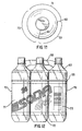
- a package having a plurality of discreet containers can have each container is positioned in the same plane and have the containers oriented so that a different part of the label of each container is visible so that along one side of the package the images on adjacent containers match up to provide a single image extending along the side of the package.
- inlet conveyor 15 feeds the plurality of containers 60 into packaging machine 20 having a plurality of jaws 22.
- the plurality of jaws 22 preferably spread the container carrier 55 and engage each container 60 with the container receiving opening.
- the container carrier tightly engages a plurality of containers, and absent a system for orienting containers, each container is rotationally positioned in a generally random orientation.
- inlet conveyor 15 feeds the plurality of containers 60 into paperboard carriers that are glued or otherwise sealed or into plastic sleeves that are shrunk wrapped or otherwise sealed.
- the plurality of containers 60 from inlet conveyor 15 are preferably fed into inlet 17 of orientation wheel 25.
- Inlet 17 may comprise inlet wheel 18 to space and singularize containers 60 prior to receipt by orientation wheel 25.
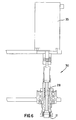
- Orientation wheel 25 is positioned to rotate each container 60 into a proper orientation and at the same time move each container 60 from inlet 17 of system toward packaging machine 20.
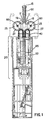
- orientation wheel 25 is generally round with a plurality of radially spaced recesses 27 formed within a perimeter, each recess 27 configured to accept one container 60 of the plurality of containers 60. Therefore, orientation wheel 25 preferably initiates or maintains singularization of the plurality of containers 60 into separate recesses 27.
- Orientation wheel 25 is not necessarily generally round and is susceptible to any other embodiment that permits singularization of containers 60.
- sensor 37 can read an existing graphic or physical characteristic of container 60, such as a design/graphic in container label 62 or a location of a seam in a sidewall of container 60 or a seam in container label 62.
- sensor 37 comprises an ultra-violet photocell.
- the ultra-violet photocell preferably reads a corresponding ultra-violet index mark positioned on each container 60.
- An ultra-violet index mark is preferably undetectable on each container 60 so as to not disturb the visual impact of container 60 and/or container label 62.
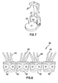
- the plurality of fingers 45 are aligned in two groups of two or more fingers 45, each two groups for engaging one oriented container 60. Such an arrangement results in oriented container 60 nestled snugly between the two groups of fingers 45 and resists rotation of each oriented container 60 and contact with each adjacent oriented container 60.
- Transfer belt 40 as shown in Figs. 2 and 3 comprises a preferred alignment of fingers 45 positioned so that each pair of adjacent links 42 contains two groups of divergent fingers 45 for accepting a single container 60.
- Transfer belt 40 preferably feeds oriented container 60 from orientation wheel 25 directly into packaging machine 20.
- a similar, associated belt operatively connected to transfer belt 40 maintains the orientation of containers 60 as such containers are fed into packaging machine 20.
- Packaging machine 20 may include the plurality of jaws 22 positioned to apply container carrier 55 over two or more oriented containers 60.
- containers 60 in corner 59 of container carrier 55 may have a visual exposure of 270° or more and containers 60 in center 57 of container carrier 55 have much less of a visual exposure. It may therefore result in a more aesthetically pleasing package if containers 60 in corners 59 of container carrier 55 are rotationally oriented so that the respective labels or graphics are centered at precise corners 59 of the package, as shown in Fig. 10.
- each 5 chuck 30 is adjusted to have a different offset so that containers 60 within container carrier 55 have at least two different orientations within a row of oriented containers 60.
- the configuration of this invention having twelve chucks 30 is thus capable of orienting containers 60 in sets of one, two, three, four, six and twelve.
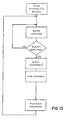
- chucks 30 may be programmed with continuous logic to accommodate rotation of a continuous flow of containers through orientation wheel 25.
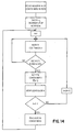
- Fig. 14 shows a flow chart for orienting containers 60 having different viewing panels 71, 72, 73 according to one preferred embodiment of this invention.
Landscapes
- Engineering & Computer Science (AREA)
- Mechanical Engineering (AREA)
- Labeling Devices (AREA)
- Container Filling Or Packaging Operations (AREA)
- Specific Conveyance Elements (AREA)
- Auxiliary Devices For And Details Of Packaging Control (AREA)
- Attitude Control For Articles On Conveyors (AREA)
- Wrapping Of Specific Fragile Articles (AREA)
- Supplying Of Containers To The Packaging Station (AREA)
- Transition And Organic Metals Composition Catalysts For Addition Polymerization (AREA)
- Closing Of Containers (AREA)
Abstract
Description
Claims (32)
- A system for use with a packaging machine for orienting containers in a container carrier, the system comprising:an inlet conveyor for feeding a plurality of containers into an inlet of the system;an orientation wheel connected with respect to the inlet, the orientation wheel for rotating the container into a proper orientation;a transfer belt connected with respect to the orientation wheel, the transfer belt for transferring an oriented container in a fixed rotational position from the orientation wheel to the packaging machine; anda mechanism positioned within the packaging machine for applying the container carrier over two or more oriented containers.
- The system of Claim 1, wherein the orientation wheel comprises:a chuck engaging one end of the container;a pressure plate securing an opposite end of the container;a motor mechanically coupled to the chuck to rotate the container; anda sensor connected with respect to the orientation wheel for locating the oriented position of the container and stopping the rotation of the motor.
- The system of Claim 2, wherein the motor repositions the container into a fixed position at a predetermined angle.
- The system of Claim 3, wherein the predetermined angle varies by containers in a set.
- The system of Claim 4, wherein the set repeats based upon a number of containers in the container carrier.
- The system of any one of Claim 2 to 5, further comprising a cam operatively connected with respect to the pressure plate for moving the pressure plate with respect to the chuck.
- The system of any one of Claim 2 to 6, wherein the chuck comprises a sleeve having an internal cavity formed to receive a bottle cap.
- The system of any one of Claim 2 to 7, wherein the sensor comprises an ultraviolet photocell.
- The system of any one of Claim 2 to 8, further comprises twelve chucks, each chuck independently programmable from each other chuck.
- The system of any one of Claim 2 to 9, wherein each container further comprises an index mark that is detected by the sensor.
- The system of any one of the preceding claims, wherein the transfer belt comprises a plurality of fingers spaced to receive the oriented containers.
- The system of Claim 11, wherein the plurality of fingers are tactile.
- The system of Claim 11 or 12, wherein the plurality of fingers are aligned in two groups of two or more fingers, each two groups for engaging one oriented container.
- The system of Claim 13, wherein two adjacent groups of two or more fingers are spaced further apart during engagement with the one oriented container than after engagement with the one oriented container.
- A system for packaging oriented containers in a container carrier, the system receiving a plurality of containers at an inlet and comprising:an orientation wheel connected with respect to the inlet, the orientation wheel including a plurality of chucks, each chuck engaging one end of the container and rotating the container into an oriented position; anda transfer belt having a plurality of tactile fingers operatively connected with respect to the orientation wheel, the transfer belt transferring an oriented container nested within the tactile fingers in a fixed rotational position from the orientation wheel to the packaging machine.
- The system of Claim 15, further comprising an ultra-violet photocell sensing a relative rotational position of the container within the chuck.
- The system of Claim 15 or 16, wherein each container further comprises an ultra-violet index mark positioned on the container.
- The system of Claim 15, 16 or 17, further comprising a cammed pressure plate lifting the container into engagement with the chuck.
- A method of packaging a plurality of containers in a container carrier comprising:feeding a plurality of containers into an orientation wheel having at least one chuck;engaging the container with the chuck; rotating the container with the chuck; sensing an index mark on the container;fixing the rotational position of the container into an oriented position;transferring an oriented container in a fixed rotational position from the orientation wheel to the packaging machine; andapplying the container carrier over two or more oriented containers.
- The method of Claim 19, further comprising:
orienting the container in a corner of the container carrier in a different orientation from the container in a center of the container carrier. - The method of Claim 19 or 20, further comprising:
moving at least a portion of the container into flush contact with the chuck. - A method of packaging a plurality of containers in a container carrier comprising:feeding a plurality of containers into an orientation wheel, each container having two or more display panels positioned circumferentially around a sidewall of each container;fixing a first rotational position of a first container of the plurality of containers into a first oriented position displaying a first display panel;fixing a second rotational position of a second container of the plurality of containers adjacent the first container into a second oriented position displaying a second display panel;transferring the first container and the second container, each separately in a fixed rotational position, from the orientation wheel to a packaging machine; andapplying the container carrier over the first container and the second container so that the first display panel and the second display panel together display a unitary display.
- The method of Claim 22, further comprising sensing the first rotational position and the second rotational position based upon an index mark positioned along the circumference of the container.
- A method of packaging a plurality of containers in a container carrier comprising:feeding a plurality of containers into an orientation system; fixing a rotational position of each container of the plurality of containers into a different oriented position from an adjacent container; transferring each container in the oriented position from the orientation system to a packaging station; andapplying the container carrier to two or more adjacent containers.
- The method of Claim 24, wherein three adjacent containers together form a unitary display in the container carrier, each container outwardly displaying a different display panel approximately 120° rotationally offset from the adjacent container.
- A package comprising:a plurality of containers, each having a first display panel and a second display panel positioned circumferentially around a perimeter;a first container of the plurality of containers positioned in a first rotational position and having a first display panel facing outward from the package;a second container of the plurality of containers positioned adjacent the first container in a second rotational position and having a second display panel facing outward from the package and together with the first display panel comprising a unitary billboard display along one longitudinal side of the package.
- The package of Claim 26, further comprising:a third display panel positioned circumferentially around the perimeter of each container of the plurality of containers; anda third container of the plurality of containers positioned adjacent the second container in a third rotational position and having a third display panel facing outward from the package, and together with the first display panel and the second display panel comprising a unitary billboard display along one longitudinal side of the package.
- A package comprising:a plurality of containers positioned in two longitudinal rows of containers, each adjacent container in the longitudinal row of containers positioned in a different rotational position relative to each other container; anda plurality of display panels positioned circumferentially around a perimeter of each container, each adjacent display panel in the longitudinal row of containers having a different outwardly facing display panel thereby forming a unitary billboard display along at least one longitudinal side of the package.
- A system for use with a packaging machine for orienting containers in a container carrier, the system comprising:
an orienter preceding the packaging machine wherein the orienter has a mechanism for individually and independently placing an oriented container at a pickup location at a front end of the packaging machine. - An apparatus for orienting containers in a container carrier comprising:an orientation wheel, the orientation wheel including a plurality of chucks, each chuck rotating the container into an oriented position;a transfer belt transferring an oriented container in a fixed rotational position from the orientation wheel to a packaging machine; andan electronic timing system used to electronically synchronize cycles of the orientation wheel with the packaging machine.
- The apparatus of Claim 30, wherein the electronic timing system comprises a proximity switch and an encoding switch in communication between the orientation wheel and the packaging machine.
- The apparatus of Claim 31, wherein the encoding switch is positioned on a rotating shaft of the packaging machine and communicates with a proximity switch on the orientation wheel for synchronizing cycles between the orientation wheel and the packaging machine.
Applications Claiming Priority (2)
| Application Number | Priority Date | Filing Date | Title |
|---|---|---|---|
| US490212 | 1990-03-08 | ||
| US09/490,212 US6484478B1 (en) | 2000-01-24 | 2000-01-24 | System and method for packaging oriented containers |
Publications (3)
| Publication Number | Publication Date |
|---|---|
| EP1120348A2 true EP1120348A2 (en) | 2001-08-01 |
| EP1120348A3 EP1120348A3 (en) | 2002-05-02 |
| EP1120348B1 EP1120348B1 (en) | 2006-04-12 |
Family
ID=23947068
Family Applications (1)
| Application Number | Title | Priority Date | Filing Date |
|---|---|---|---|
| EP01300170A Expired - Lifetime EP1120348B1 (en) | 2000-01-24 | 2001-01-10 | System and method for orienting containers |
Country Status (17)
| Country | Link |
|---|---|
| US (2) | US6484478B1 (en) |
| EP (1) | EP1120348B1 (en) |
| JP (1) | JP4699602B2 (en) |
| KR (1) | KR100746599B1 (en) |
| CN (1) | CN1234570C (en) |
| AT (1) | ATE323027T1 (en) |
| AU (1) | AU751918B2 (en) |
| BR (1) | BR0100117A (en) |
| CA (1) | CA2327054C (en) |
| DE (1) | DE60118636T2 (en) |
| DK (1) | DK1120348T3 (en) |
| ES (1) | ES2261343T3 (en) |
| MX (1) | MXPA01000778A (en) |
| NO (1) | NO325372B1 (en) |
| NZ (1) | NZ509484A (en) |
| PT (1) | PT1120348E (en) |
| TW (1) | TW466201B (en) |
Cited By (3)
| Publication number | Priority date | Publication date | Assignee | Title |
|---|---|---|---|---|
| DE102011082972A1 (en) * | 2011-09-19 | 2013-03-21 | Maschinenfabrik Gerd Mosca Ag | Bundle i.e. bottle bundle, has two containers arranged such that partial motifs are simultaneously viewable in viewing direction and formed complement to entire motif, where motifs are located on two surfaces of two containers, respectively |
| WO2016071188A1 (en) * | 2014-11-04 | 2016-05-12 | Lissmac Maschinenbau Gmbh | Device comprising a turning unit for turning a workpiece and machining device |
| WO2019147456A1 (en) * | 2018-01-23 | 2019-08-01 | The Procter & Gamble Company | Alignment of a window on a container |
Families Citing this family (47)
| Publication number | Priority date | Publication date | Assignee | Title |
|---|---|---|---|---|
| US6868652B2 (en) * | 2000-01-24 | 2005-03-22 | Illinois Tool Works, Inc. | System and method for packaging oriented containers |
| PT1177976E (en) * | 2000-07-03 | 2004-04-30 | Tetra Laval Holdings & Finance | PACKAGING MACHINER FOR CONTINUOUSLY PRODUCING SEALED PACKAGING OF A FOOD PRODUCT THAT CAN BE DUMPED AND PHOTOELECTRIC CHARACTERIZATION CELLS THAT CAN BE SCHEDULED |
| JP2003335383A (en) * | 2002-05-14 | 2003-11-25 | Uni Charm Corp | Double packaging body |
| US7448497B2 (en) * | 2002-12-30 | 2008-11-11 | Fck, Llc. | Batteries, accessories, marketing bundles and marketing methods |
| DE10306671A1 (en) | 2003-02-18 | 2004-08-26 | Khs Maschinen- Und Anlagenbau Ag | Modules for labeling machines |
| US20040232023A1 (en) * | 2003-05-21 | 2004-11-25 | Unilever Bestfoods North America | Asymmetric package for market appeal |
| US20060070272A1 (en) * | 2004-09-27 | 2006-04-06 | E. & J. Gallo Winery | Point of sale single bottle sign holder |
| US20060175283A1 (en) * | 2005-01-28 | 2006-08-10 | Graham Packaging Company, L.P. | Plastic container with improved petaloidal base |
| AT501865B1 (en) * | 2005-05-30 | 2007-04-15 | Andreas Zaglacher | BOTTLE ORGANIZERS |
| ATE393110T1 (en) * | 2005-07-01 | 2008-05-15 | Seidel Helmut | DEVICE FOR CONVEYING AND ROTating OBJECTS |
| US20070102316A1 (en) * | 2005-11-08 | 2007-05-10 | Conopco, Inc., D/B/A Unilever | Packaging with continuing labels |
| US7806257B2 (en) * | 2006-05-02 | 2010-10-05 | Illinois Tool Works Inc. | Single color bar code printing on a multi-package |
| US7819243B2 (en) * | 2006-05-02 | 2010-10-26 | Illinois Tool Works Inc. | Bar code blocking package |
| US7721879B2 (en) | 2006-05-02 | 2010-05-25 | Illinois Tool Works Inc. | Bar code blocking package |
| US7775020B2 (en) * | 2006-05-02 | 2010-08-17 | Illinois Tool Works Inc. | Bar code blocking package |
| US20080105593A1 (en) * | 2006-11-03 | 2008-05-08 | The Procter & Gamble Company | Panoramic product display assembly |
| US20080265041A1 (en) * | 2007-04-30 | 2008-10-30 | David Brophy | Bar code blocking system |
| US20080308443A1 (en) * | 2007-06-13 | 2008-12-18 | Baxter International Inc. | Packaging system and method of use |
| US20080308444A1 (en) * | 2007-06-13 | 2008-12-18 | Baxter International Inc. | Packaging system and method of alerting a practitioner |
| ES2338397B1 (en) * | 2008-01-14 | 2011-02-10 | Girnet International, S.L. | PROCEDURE FOR THE CONTINUOUS DEVELOPMENT OF MESH BAGS. |
| GB0806884D0 (en) * | 2008-04-16 | 2008-05-21 | Meadwestvaco Packaging Systems | Article orientating device |
| DE102008044696A1 (en) * | 2008-08-28 | 2010-03-04 | Khs Ag | lock orientation |
| DE102008059229A1 (en) * | 2008-11-20 | 2010-06-02 | Khs Ag | Method for aligning a container |
| US20100264058A1 (en) * | 2009-04-15 | 2010-10-21 | Bio Clinical Development, Inc. | Product multi-pack |
| US20100294690A1 (en) * | 2009-05-19 | 2010-11-25 | The Coca-Cola Plaza Nw | Package displaying a holistic message |
| DE102009058086A1 (en) | 2009-12-14 | 2011-06-16 | Krones Ag | Apparatus and method for treating containers with clothing detection |
| DE102010054792A1 (en) * | 2010-12-16 | 2012-06-21 | Krones Aktiengesellschaft | Device for treating containers with container orientation |
| DE102012100810B4 (en) * | 2011-12-02 | 2014-12-24 | Khs Gmbh | Device for forming packaging units |
| DE102011119967B3 (en) * | 2011-12-02 | 2013-01-17 | Khs Gmbh | Apparatus and method for forming packaging units |
| US20130180140A1 (en) * | 2012-01-16 | 2013-07-18 | Nokia Corporation | Packaging display system |
| DE102012007778A1 (en) * | 2012-02-01 | 2013-08-01 | Khs Gmbh | Oval container treatment device |
| GB201217466D0 (en) * | 2012-09-29 | 2012-11-14 | Meadwestvaco Packaging System Llc | Packaging machine and method of packaging articles |
| CN103043235B (en) * | 2012-12-12 | 2015-10-28 | 天津仁义合自动化技术有限公司 | Automatic packing production chain |
| CN103274196B (en) * | 2013-05-17 | 2015-09-02 | 广州市铭慧机械股份有限公司 | The orienting device of abnormity material |
| ES2898656T3 (en) * | 2014-06-30 | 2022-03-08 | Nutricos Tech | Combination products and cosmetic compositions to combat skin disorders and skin aging affecting keratinocytes and/or fibroblasts and the dermis |
| JP7345393B2 (en) * | 2017-02-01 | 2023-09-15 | ウエストロック・パッケージング・システムズ・エルエルシー | Apparatus, system and method for orienting articles |
| US20180327141A1 (en) * | 2017-05-10 | 2018-11-15 | Anheuser-Busch, Llc | Beverage containers with tactile elements |
| US11713145B2 (en) * | 2019-03-04 | 2023-08-01 | Illinois Tool Works Inc. | Variable pitch starwheel for container carrier applicating machine |
| DE102019203289A1 (en) * | 2019-03-11 | 2020-09-17 | Krones Aktiengesellschaft | Method and device for layer formation or palletizing of articles, piece goods and / or bundles, as well as layer or pallet arrangement formed by means of such a method |
| IT201900023040A1 (en) * | 2019-12-05 | 2021-06-05 | Ocme Srl | GROUPING UNIT OF CYLINDRICAL CONTAINERS AND RELATIVE METHOD. |
| BR112022021755A2 (en) | 2020-05-29 | 2022-12-13 | Graphic Packaging Int Llc | METHOD FOR CHANGING THE ARTICLE ARRANGEMENT, AND SYSTEM FOR AT LEAST PARTIALLY CHANGING THE ARTICLE ARRANGEMENT |
| EP4172054A1 (en) * | 2020-06-30 | 2023-05-03 | Société des Produits Nestlé S.A. | Multipack of several containers held together by adhesive |
| ES2992935T3 (en) | 2020-07-09 | 2024-12-19 | Procter & Gamble | Detergent product container |
| HUE064933T2 (en) | 2020-07-09 | 2024-05-28 | Procter & Gamble | Detergent product and container |
| EP3943424A1 (en) | 2020-07-24 | 2022-01-26 | WestRock Packaging Systems, LLC | Smooth handoff of containers using multiple grippers |
| EP3943428A1 (en) * | 2020-07-24 | 2022-01-26 | WestRock Packaging Systems, LLC | Orientation module |
| EP4238876B1 (en) | 2022-01-14 | 2025-03-05 | The Procter & Gamble Company | Process for forming a hood for a tray |
Family Cites Families (39)
| Publication number | Priority date | Publication date | Assignee | Title |
|---|---|---|---|---|
| US2648156A (en) * | 1947-07-30 | 1953-08-11 | Colgate William Homer | Dual container with viewing window |
| US2528912A (en) * | 1949-05-02 | 1950-11-07 | Wright Machinery Co | Spotter mechanism |
| US2885839A (en) * | 1955-01-11 | 1959-05-12 | American Can Co | Banding machine |
| US3415350A (en) * | 1966-10-24 | 1968-12-10 | Fmc Corp | Article orienting apparatus |
| US3451523A (en) * | 1967-07-14 | 1969-06-24 | Mandrel Industries | Container orienter |
| FR1545680A (en) | 1967-08-01 | 1968-11-15 | Chassaing Le Coq & Cie | Machine for packing jars in display cartridges |
| US3541751A (en) * | 1968-09-18 | 1970-11-24 | Illinois Tool Works | Method and apparatus for packaging a plurality of articles in predetermined arrangement |
| US3618743A (en) * | 1969-11-05 | 1971-11-09 | Mead Corp | Article-orienting device |
| US3635322A (en) | 1970-02-24 | 1972-01-18 | Emhart Corp | Conveyor system for dividing a line of articles into several discrete lanes |
| US3717942A (en) * | 1971-03-16 | 1973-02-27 | B Presby | Rotatable amusement and education device |
| US3811243A (en) | 1972-03-31 | 1974-05-21 | Grip Pak Inc | Method of assembling multi-packaging devices to articles |
| US3910412A (en) * | 1973-03-08 | 1975-10-07 | Filter Dynamics International | Point of sales packaging and display system |
| US3816968A (en) * | 1973-05-03 | 1974-06-18 | Illinois Tool Works | Drum assembly for container carrier machine |
| US3848394A (en) | 1973-06-26 | 1974-11-19 | R Heisler | Apparatus and method for orienting and case packing eared containers |
| US3934714A (en) | 1974-05-09 | 1976-01-27 | Yamamura Glass Kabushiki Kaisha | Method and apparatus for regulating orientation of containers or the like |
| US4051366A (en) | 1975-12-31 | 1977-09-27 | United Technologies Corporation | Optical apparatus for sensing clustered package orientation |
| US4143754A (en) * | 1977-07-07 | 1979-03-13 | Morgan Fairest Limited | Labelling machines with article guide plate |
| DE2752193C2 (en) * | 1977-11-23 | 1985-11-07 | Optima-Maschinenfabrik Dr. Bühler GmbH & Co, 7170 Schwäbisch Hall | Transport device for series products within a weighing device |
| US4383601A (en) | 1980-05-27 | 1983-05-17 | Heisler Raymond A | Apparatus for sensing, orientating and delivering cans to subsequent conveyor |
| US4344522A (en) | 1980-05-27 | 1982-08-17 | Heisler Raymond A | Apparatus for sensing, orientating and delivering cans to subsequent conveyor |
| DE3022343C2 (en) | 1980-06-14 | 1983-10-20 | Kronseder, Hermann, 8404 Wörth | Device for aligning bottles or the like., In particular in labeling machines |
| US4596330A (en) | 1981-08-10 | 1986-06-24 | Benno Edward L | Multipackages, the packaging elements, and the method for making the multipackages |
| JPS5978321U (en) * | 1982-11-18 | 1984-05-26 | サッポロビール株式会社 | Object direction regulating device |
| US4640406A (en) | 1984-10-03 | 1987-02-03 | Feco Engineered Systems, Inc. | Rotational and retractable container holding device and conveyor therefor |
| GB8728486D0 (en) | 1987-12-04 | 1988-01-13 | Metal Box Plc | Orientation of containers |
| FR2652059B1 (en) | 1989-09-19 | 1991-12-20 | Ouest Conditionnement | MACHINE FOR PACKAGING OBJECTS SUCH AS BOTTLES OR CANNES IN A GROUP AND ORIENTED CONDITION. |
| JPH03124523A (en) * | 1989-10-05 | 1991-05-28 | Kirin Brewery Co Ltd | Apparatus for boxing |
| DE9006376U1 (en) * | 1990-06-06 | 1991-05-02 | Krones Ag Hermann Kronseder Maschinenfabrik, 93073 Neutraubling | Device for centering and aligning vessels |
| US5161664A (en) * | 1990-03-13 | 1992-11-10 | The Mead Corporation | Infeed grouping mechanism for a packaging machine |
| US5058724A (en) | 1990-11-08 | 1991-10-22 | Hinton Gaylen R | Apparatus and method for orienting articles and containers |
| US5215180A (en) * | 1991-06-06 | 1993-06-01 | Carnaudmetalbox Plc | Can orientation apparatus |
| JPH05193633A (en) * | 1991-12-19 | 1993-08-03 | Shibuya Kogyo Co Ltd | Container positioning device |
| JP2566002Y2 (en) * | 1993-03-25 | 1998-03-25 | 鐘紡株式会社 | Container loading device |
| JP3321917B2 (en) * | 1993-07-02 | 2002-09-09 | 澁谷工業株式会社 | Label processing equipment for collection containers |
| US5430992A (en) * | 1993-09-20 | 1995-07-11 | Riverwood International Corporation | Stacked article carrier packaging |
| US5492222A (en) * | 1994-04-13 | 1996-02-20 | Illinois Tool Works Inc. | Bar code blocking carrier |
| SE503842C2 (en) * | 1994-10-08 | 1996-09-16 | Haakan Edqvist | Method and apparatus for determining cylindrical objects |
| IT1287582B1 (en) * | 1996-12-12 | 1998-08-06 | Ima Spa | CONTAINER TRANSPORT DEVICE, IN PARTICULAR BOTTLES AND BOTTLES, THROUGH DIFFERENT OPERATING STATIONS |
| JPH11165709A (en) * | 1997-12-03 | 1999-06-22 | Fabrica Toyama Corp | Corrugated board caser |
-
2000
- 2000-01-24 US US09/490,212 patent/US6484478B1/en not_active Expired - Lifetime
- 2000-11-28 KR KR1020000071106A patent/KR100746599B1/en not_active Expired - Fee Related
- 2000-11-29 CA CA002327054A patent/CA2327054C/en not_active Expired - Lifetime
- 2000-12-15 TW TW089127004A patent/TW466201B/en not_active IP Right Cessation
- 2000-12-22 JP JP2000390797A patent/JP4699602B2/en not_active Expired - Fee Related
-
2001
- 2001-01-10 DE DE60118636T patent/DE60118636T2/en not_active Expired - Lifetime
- 2001-01-10 PT PT01300170T patent/PT1120348E/en unknown
- 2001-01-10 AT AT01300170T patent/ATE323027T1/en active
- 2001-01-10 ES ES01300170T patent/ES2261343T3/en not_active Expired - Lifetime
- 2001-01-10 DK DK01300170T patent/DK1120348T3/en active
- 2001-01-10 EP EP01300170A patent/EP1120348B1/en not_active Expired - Lifetime
- 2001-01-12 CN CNB011018046A patent/CN1234570C/en not_active Expired - Lifetime
- 2001-01-12 AU AU14968/01A patent/AU751918B2/en not_active Expired
- 2001-01-19 NZ NZ509484A patent/NZ509484A/en not_active IP Right Cessation
- 2001-01-19 BR BR0100117-5A patent/BR0100117A/en not_active IP Right Cessation
- 2001-01-22 MX MXPA01000778A patent/MXPA01000778A/en active IP Right Grant
- 2001-01-23 NO NO20010394A patent/NO325372B1/en not_active IP Right Cessation
-
2002
- 2002-10-25 US US10/280,205 patent/US6688465B2/en not_active Expired - Lifetime
Cited By (3)
| Publication number | Priority date | Publication date | Assignee | Title |
|---|---|---|---|---|
| DE102011082972A1 (en) * | 2011-09-19 | 2013-03-21 | Maschinenfabrik Gerd Mosca Ag | Bundle i.e. bottle bundle, has two containers arranged such that partial motifs are simultaneously viewable in viewing direction and formed complement to entire motif, where motifs are located on two surfaces of two containers, respectively |
| WO2016071188A1 (en) * | 2014-11-04 | 2016-05-12 | Lissmac Maschinenbau Gmbh | Device comprising a turning unit for turning a workpiece and machining device |
| WO2019147456A1 (en) * | 2018-01-23 | 2019-08-01 | The Procter & Gamble Company | Alignment of a window on a container |
Also Published As
| Publication number | Publication date |
|---|---|
| US20030047475A1 (en) | 2003-03-13 |
| DE60118636T2 (en) | 2006-08-31 |
| JP4699602B2 (en) | 2011-06-15 |
| CA2327054A1 (en) | 2001-07-24 |
| AU1496801A (en) | 2001-07-26 |
| ES2261343T3 (en) | 2006-11-16 |
| EP1120348A3 (en) | 2002-05-02 |
| PT1120348E (en) | 2006-07-31 |
| EP1120348B1 (en) | 2006-04-12 |
| NO20010394D0 (en) | 2001-01-23 |
| CA2327054C (en) | 2005-07-05 |
| KR100746599B1 (en) | 2007-08-08 |
| US6484478B1 (en) | 2002-11-26 |
| ATE323027T1 (en) | 2006-04-15 |
| TW466201B (en) | 2001-12-01 |
| DE60118636D1 (en) | 2006-05-24 |
| DK1120348T3 (en) | 2006-08-21 |
| BR0100117A (en) | 2001-08-28 |
| KR20010076228A (en) | 2001-08-11 |
| NO325372B1 (en) | 2008-04-14 |
| JP2001213408A (en) | 2001-08-07 |
| NZ509484A (en) | 2002-12-20 |
| AU751918B2 (en) | 2002-08-29 |
| CN1319536A (en) | 2001-10-31 |
| CN1234570C (en) | 2006-01-04 |
| US6688465B2 (en) | 2004-02-10 |
| MXPA01000778A (en) | 2001-10-16 |
| NO20010394L (en) | 2001-07-25 |
Similar Documents
| Publication | Publication Date | Title |
|---|---|---|
| EP1120348B1 (en) | System and method for orienting containers | |
| EP1495973B1 (en) | Device for orienting containers | |
| US8903540B2 (en) | Automatic container orientation systems and methods | |
| US20100192515A1 (en) | Article alignment apparatus | |
| US5919028A (en) | Method and a device for positioning cylindrical items | |
| WO1996011140A9 (en) | A method and a device for positioning cylindrical items | |
| US20100192525A1 (en) | Clamping transfer turret | |
| JPH0899710A (en) | Fixed position arranging device for can body |
Legal Events
| Date | Code | Title | Description |
|---|---|---|---|
| PUAI | Public reference made under article 153(3) epc to a published international application that has entered the european phase |
Free format text: ORIGINAL CODE: 0009012 |
|
| AK | Designated contracting states |
Kind code of ref document: A2 Designated state(s): AT BE CH CY DE DK ES FI FR GB GR IE IT LI LU MC NL PT SE TR |
|
| AX | Request for extension of the european patent |
Free format text: AL;LT;LV;MK;RO;SI |
|
| PUAL | Search report despatched |
Free format text: ORIGINAL CODE: 0009013 |
|
| AK | Designated contracting states |
Kind code of ref document: A3 Designated state(s): AT BE CH CY DE DK ES FI FR GB GR IE IT LI LU MC NL PT SE TR |
|
| AX | Request for extension of the european patent |
Free format text: AL;LT;LV;MK;RO;SI |
|
| RIC1 | Information provided on ipc code assigned before grant |
Free format text: 7B 65C 9/06 A, 7B 65B 35/58 B, 7B 65B 21/04 B, 7B 65G 47/244 B, 7B 65G 47/84 B |
|
| 17P | Request for examination filed |
Effective date: 20021014 |
|
| AKX | Designation fees paid |
Free format text: AT BE CH CY DE DK ES FI FR GB GR IE IT LI LU MC NL PT SE TR |
|
| 17Q | First examination report despatched |
Effective date: 20040206 |
|
| RTI1 | Title (correction) |
Free format text: SYSTEM AND METHOD FOR ORIENTING CONTAINERS AND OBTAINED PACKAGE |
|
| GRAP | Despatch of communication of intention to grant a patent |
Free format text: ORIGINAL CODE: EPIDOSNIGR1 |
|
| RTI1 | Title (correction) |
Free format text: SYSTEM AND METHOD FOR ORIENTING CONTAINERS |
|
| GRAS | Grant fee paid |
Free format text: ORIGINAL CODE: EPIDOSNIGR3 |
|
| GRAA | (expected) grant |
Free format text: ORIGINAL CODE: 0009210 |
|
| AK | Designated contracting states |
Kind code of ref document: B1 Designated state(s): AT BE CH CY DE DK ES FI FR GB GR IE IT LI LU MC NL PT SE TR |
|
| PG25 | Lapsed in a contracting state [announced via postgrant information from national office to epo] |
Ref country code: IT Free format text: LAPSE BECAUSE OF FAILURE TO SUBMIT A TRANSLATION OF THE DESCRIPTION OR TO PAY THE FEE WITHIN THE PRESCRIBED TIME-LIMIT;WARNING: LAPSES OF ITALIAN PATENTS WITH EFFECTIVE DATE BEFORE 2007 MAY HAVE OCCURRED AT ANY TIME BEFORE 2007. THE CORRECT EFFECTIVE DATE MAY BE DIFFERENT FROM THE ONE RECORDED. Effective date: 20060412 |
|
| REG | Reference to a national code |
Ref country code: GB Ref legal event code: FG4D |
|
| REG | Reference to a national code |
Ref country code: CH Ref legal event code: EP |
|
| REG | Reference to a national code |
Ref country code: SE Ref legal event code: TRGR |
|
| REG | Reference to a national code |
Ref country code: CH Ref legal event code: NV Representative=s name: E. BLUM & CO. PATENTANWAELTE |
|
| REF | Corresponds to: |
Ref document number: 60118636 Country of ref document: DE Date of ref document: 20060524 Kind code of ref document: P |
|
| REG | Reference to a national code |
Ref country code: IE Ref legal event code: FG4D |
|
| REG | Reference to a national code |
Ref country code: GR Ref legal event code: EP Ref document number: 20060401310 Country of ref document: GR |
|
| REG | Reference to a national code |
Ref country code: PT Ref legal event code: SC4A Effective date: 20060516 |
|
| REG | Reference to a national code |
Ref country code: DK Ref legal event code: T3 |
|
| ET | Fr: translation filed | ||
| REG | Reference to a national code |
Ref country code: ES Ref legal event code: FG2A Ref document number: 2261343 Country of ref document: ES Kind code of ref document: T3 |
|
| PG25 | Lapsed in a contracting state [announced via postgrant information from national office to epo] |
Ref country code: MC Free format text: LAPSE BECAUSE OF NON-PAYMENT OF DUE FEES Effective date: 20070131 |
|
| PLBE | No opposition filed within time limit |
Free format text: ORIGINAL CODE: 0009261 |
|
| STAA | Information on the status of an ep patent application or granted ep patent |
Free format text: STATUS: NO OPPOSITION FILED WITHIN TIME LIMIT |
|
| 26N | No opposition filed |
Effective date: 20070115 |
|
| REG | Reference to a national code |
Ref country code: CH Ref legal event code: PFA Owner name: ILLINOIS TOOL WORKS INC. Free format text: ILLINOIS TOOL WORKS INC.#3600 WEST LAKE AVENUE#GLENVIEW, ILLINOIS 60025 (US) -TRANSFER TO- ILLINOIS TOOL WORKS INC.#3600 WEST LAKE AVENUE#GLENVIEW, ILLINOIS 60025 (US) |
|
| PGFP | Annual fee paid to national office [announced via postgrant information from national office to epo] |
Ref country code: GR Payment date: 20090129 Year of fee payment: 9 |
|
| PG25 | Lapsed in a contracting state [announced via postgrant information from national office to epo] |
Ref country code: LU Free format text: LAPSE BECAUSE OF NON-PAYMENT OF DUE FEES Effective date: 20070110 Ref country code: CY Free format text: LAPSE BECAUSE OF FAILURE TO SUBMIT A TRANSLATION OF THE DESCRIPTION OR TO PAY THE FEE WITHIN THE PRESCRIBED TIME-LIMIT Effective date: 20060412 |
|
| PGFP | Annual fee paid to national office [announced via postgrant information from national office to epo] |
Ref country code: SE Payment date: 20090128 Year of fee payment: 9 |
|
| PG25 | Lapsed in a contracting state [announced via postgrant information from national office to epo] |
Ref country code: TR Free format text: LAPSE BECAUSE OF FAILURE TO SUBMIT A TRANSLATION OF THE DESCRIPTION OR TO PAY THE FEE WITHIN THE PRESCRIBED TIME-LIMIT Effective date: 20060412 |
|
| EUG | Se: european patent has lapsed | ||
| PG25 | Lapsed in a contracting state [announced via postgrant information from national office to epo] |
Ref country code: SE Free format text: LAPSE BECAUSE OF NON-PAYMENT OF DUE FEES Effective date: 20100111 |
|
| PGFP | Annual fee paid to national office [announced via postgrant information from national office to epo] |
Ref country code: AT Payment date: 20111221 Year of fee payment: 12 |
|
| REG | Reference to a national code |
Ref country code: AT Ref legal event code: MM01 Ref document number: 323027 Country of ref document: AT Kind code of ref document: T Effective date: 20130131 |
|
| PG25 | Lapsed in a contracting state [announced via postgrant information from national office to epo] |
Ref country code: AT Free format text: LAPSE BECAUSE OF NON-PAYMENT OF DUE FEES Effective date: 20130131 |
|
| PGFP | Annual fee paid to national office [announced via postgrant information from national office to epo] |
Ref country code: DK Payment date: 20140127 Year of fee payment: 14 Ref country code: IE Payment date: 20140127 Year of fee payment: 14 Ref country code: FI Payment date: 20140129 Year of fee payment: 14 Ref country code: BE Payment date: 20140127 Year of fee payment: 14 |
|
| REG | Reference to a national code |
Ref country code: FR Ref legal event code: PLFP Year of fee payment: 15 |
|
| PGFP | Annual fee paid to national office [announced via postgrant information from national office to epo] |
Ref country code: FR Payment date: 20150119 Year of fee payment: 15 |
|
| PG25 | Lapsed in a contracting state [announced via postgrant information from national office to epo] |
Ref country code: BE Free format text: LAPSE BECAUSE OF NON-PAYMENT OF DUE FEES Effective date: 20150131 |
|
| REG | Reference to a national code |
Ref country code: DK Ref legal event code: EBP Effective date: 20150131 |
|
| PG25 | Lapsed in a contracting state [announced via postgrant information from national office to epo] |
Ref country code: FI Free format text: LAPSE BECAUSE OF NON-PAYMENT OF DUE FEES Effective date: 20150110 |
|
| REG | Reference to a national code |
Ref country code: IE Ref legal event code: MM4A |
|
| PG25 | Lapsed in a contracting state [announced via postgrant information from national office to epo] |
Ref country code: IE Free format text: LAPSE BECAUSE OF NON-PAYMENT OF DUE FEES Effective date: 20150110 Ref country code: DK Free format text: LAPSE BECAUSE OF NON-PAYMENT OF DUE FEES Effective date: 20150131 |
|
| REG | Reference to a national code |
Ref country code: FR Ref legal event code: ST Effective date: 20160930 |
|
| PG25 | Lapsed in a contracting state [announced via postgrant information from national office to epo] |
Ref country code: FR Free format text: LAPSE BECAUSE OF NON-PAYMENT OF DUE FEES Effective date: 20160201 |
|
| PGFP | Annual fee paid to national office [announced via postgrant information from national office to epo] |
Ref country code: CH Payment date: 20180127 Year of fee payment: 18 |
|
| REG | Reference to a national code |
Ref country code: CH Ref legal event code: PL |
|
| PG25 | Lapsed in a contracting state [announced via postgrant information from national office to epo] |
Ref country code: CH Free format text: LAPSE BECAUSE OF NON-PAYMENT OF DUE FEES Effective date: 20190131 Ref country code: LI Free format text: LAPSE BECAUSE OF NON-PAYMENT OF DUE FEES Effective date: 20190131 |
|
| PGFP | Annual fee paid to national office [announced via postgrant information from national office to epo] |
Ref country code: PT Payment date: 20191220 Year of fee payment: 20 |
|
| PGFP | Annual fee paid to national office [announced via postgrant information from national office to epo] |
Ref country code: GB Payment date: 20200127 Year of fee payment: 20 Ref country code: IT Payment date: 20200123 Year of fee payment: 20 Ref country code: NL Payment date: 20200126 Year of fee payment: 20 Ref country code: ES Payment date: 20200205 Year of fee payment: 20 Ref country code: DE Payment date: 20200129 Year of fee payment: 20 |
|
| REG | Reference to a national code |
Ref country code: DE Ref legal event code: R071 Ref document number: 60118636 Country of ref document: DE |
|
| REG | Reference to a national code |
Ref country code: NL Ref legal event code: MK Effective date: 20210109 |
|
| REG | Reference to a national code |
Ref country code: GB Ref legal event code: PE20 Expiry date: 20210109 |
|
| PG25 | Lapsed in a contracting state [announced via postgrant information from national office to epo] |
Ref country code: GB Free format text: LAPSE BECAUSE OF EXPIRATION OF PROTECTION Effective date: 20210109 Ref country code: PT Free format text: LAPSE BECAUSE OF EXPIRATION OF PROTECTION Effective date: 20210121 |
|
| REG | Reference to a national code |
Ref country code: ES Ref legal event code: FD2A Effective date: 20210625 |
|
| PG25 | Lapsed in a contracting state [announced via postgrant information from national office to epo] |
Ref country code: ES Free format text: LAPSE BECAUSE OF EXPIRATION OF PROTECTION Effective date: 20210111 |