EP1120150B1 - Appareil de séparation à membranes - Google Patents
Appareil de séparation à membranes Download PDFInfo
- Publication number
- EP1120150B1 EP1120150B1 EP00124686A EP00124686A EP1120150B1 EP 1120150 B1 EP1120150 B1 EP 1120150B1 EP 00124686 A EP00124686 A EP 00124686A EP 00124686 A EP00124686 A EP 00124686A EP 1120150 B1 EP1120150 B1 EP 1120150B1
- Authority
- EP
- European Patent Office
- Prior art keywords
- membrane
- separator according
- membrane separator
- spacer
- height
- Prior art date
- Legal status (The legal status is an assumption and is not a legal conclusion. Google has not performed a legal analysis and makes no representation as to the accuracy of the status listed.)
- Expired - Lifetime
Links
Images


Classifications
-
- B—PERFORMING OPERATIONS; TRANSPORTING
- B01—PHYSICAL OR CHEMICAL PROCESSES OR APPARATUS IN GENERAL
- B01D—SEPARATION
- B01D65/00—Accessories or auxiliary operations, in general, for separation processes or apparatus using semi-permeable membranes
- B01D65/08—Prevention of membrane fouling or of concentration polarisation
-
- B—PERFORMING OPERATIONS; TRANSPORTING
- B01—PHYSICAL OR CHEMICAL PROCESSES OR APPARATUS IN GENERAL
- B01D—SEPARATION
- B01D63/00—Apparatus in general for separation processes using semi-permeable membranes
- B01D63/10—Spiral-wound membrane modules
-
- B—PERFORMING OPERATIONS; TRANSPORTING
- B01—PHYSICAL OR CHEMICAL PROCESSES OR APPARATUS IN GENERAL
- B01D—SEPARATION
- B01D2321/00—Details relating to membrane cleaning, regeneration, sterilization or to the prevention of fouling
- B01D2321/20—By influencing the flow
- B01D2321/2008—By influencing the flow statically
- B01D2321/2016—Static mixers; Turbulence generators
Definitions
- the invention relates to a membrane separation device for separating low-colloidal and low molecular weight pollutants and polyvalent ions (heavy metals) from aqueous media according to the preamble of claim 1.
- Oxidative processes are predominantly used in the chemical processes, with hydrogen peroxide (H 2 O 2 ) or ozone (O 3 ) being used, for example.
- the membrane separation processes used here are the micro-, ultra-, and nanofiltration as well as the reverse osmosis.
- the mentioned methods are pressure-driven and differ in the transmembrane pressure difference and in the separation limit.
- the microfiltration operates in a pressure range of 1-10 bar and separates substances with a size of 0.075-5 ⁇ m occasionally up to 10 ⁇ m.
- the ultrafiltration operates at pressures of 1-10 bar and with pore sizes around 0.005-0.2 ⁇ m.
- the pores of the polymer membranes are more or less circular, for retention determination the mean molecular diameter in relation to the pore diameter is more distinct than the molecular weight.
- the separated substances form on the membrane surface of the feed side a cover layer as a secondary membrane, which is crucial for the separation behavior of the process.
- the cover layer serves as a kind of second filter.
- the permeate flux drops drastically.
- This cover layer may have a balance between degradation and reformation. Ie. the river adjusts to a steady end value.
- the nanofiltration process employs pore-free membranes.
- the permeating components on the feed side go into the membrane in solution, diffuse through the membrane and desorb on the permeate side.
- the correct pH-adjustment of the medium is important for a sufficient permeate quality.
- the pH must be greater than 7, since at lower pH values, the free H + ions neutralize the negative charges on the membrane and thus insufficient retention can be achieved.
- spiral winding elements in particular in diffusive membrane separation processes (NF and RO), represent a very economical modular design.
- the figure 1a shows different Spacerformen in plan view
- Diamond spacers should only be used on simple homogeneous media that do not agglomerate and do not cause scaling (crystalline precipitation), eg. B. pretreated drinking water, ionic solutions and emulsions.
- Parallel spacers are suitable for simple heterogeneous solutions. In this Spacerform certain turbidity without particulate precipitates can still be allowed, such. Controlled overflow of biology, colloidal solutions, pigments and proteins contained in the solvent.
- Tubular spacers can be used in complex heterogeneous solutions. Concentration of these complex media can form precipitates of various kinds, such as crystalline precipitation (scaling) and composition of low-particulate constituents (agglomeration), eg. B. from industrial wastewater, mother liquor for regeneration, rinsing wastewater from ion exchanger and recycled water from bottle washing systems.
- precipitates of various kinds, such as crystalline precipitation (scaling) and composition of low-particulate constituents (agglomeration), eg. B. from industrial wastewater, mother liquor for regeneration, rinsing wastewater from ion exchanger and recycled water from bottle washing systems.
- Fouling can occur regardless of the selection for all three spacer shapes.
- a dry cleaning or tubular spacers with non-porous membranes a rinse with dramatically increased fürströrnungs Republic help.
- the tubular spacer ensures less turbulence of the medium even at higher flow rates.
- the tubular spacer thus requires a higher flow rate, but this has a higher energy consumption.
- the membrane surface is occupied faster when using the tubular spacer with less flow.
- a semi-permeable membrane separation device which comprises membrane winding elements, between whose winding layers wavy spacer elements are arranged.
- These spacer elements consist of a plastic film, the two sides of which have a shaft half offset from one another arranged wave structures, which rest in each case with their wave crests on the membrane winding layers. Measures for turbulence increase der.Strömung in the flow channels formed by the wave troughs are not provided.
- a membrane module for a water treatment device with spirally wound membrane winding elements. Between the winding layers zigzag spacing elements are arranged. On the lateral flanks of the zigzag-shaped spacer elements, spaced projections extending to the ridge are formed for generating of flow turbulences.
- these projections acting as turbulence elements increase the membrane coverage, thereby reducing the free, effective membrane area and reducing the separation efficiency of the device.
- the object of the present invention is to provide a membrane separation device with spiral winding elements in such a way that the effective membrane area increases, the risk of fouling minimized and the volume flow can be reduced.
- FIG. 1 and 2 show a known sine wave-shaped spacer 2 between two membrane layers 4, 6 of a winding element in the unloaded state.
- the reference numeral 8 denotes permeate membrane pockets.
- the angle ⁇ between the membrane and the spacer is relatively small, which is technically unfavorable in terms of flow and entails the risk that solids settle, resulting in increased risk of fouling. Due to the ever occurring Wikkeldruck is in practical operation on the membrane adjacent rounding of the spacer flattened, see. Fig. 2, whereby on the one hand the free effective membrane area is reduced and also reduces the angle ⁇ . As a result, the flow through the spacer deteriorates and increases the risk of fouling.
- Fig. 3 shows a known spacer element 20 in waveform, in which the wave crests 21 and wave troughs 22 are U-shaped.
- the U-web 24 of the wave crests and wave troughs is formed part-circular or arcuate.
- the U-legs 26 of the wave crests and wave troughs are arranged approximately perpendicular to the membrane surfaces 28.
- This design results in a larger angle ⁇ between the membrane surface 28 and the spacer than in the known embodiment according to FIGS. 1 and 2.
- the stability is improved and also the flattening effect by the winding pressure is lower.
- the membrane area covered by the spacer 20 per shaft half is still relatively large.
- the flow cross-section is also relatively large, so that there are correspondingly large volume flows.
- FIG. 4 shows a known spacer element 30 in a zigzag shape, ie the wave crests 31 and wave troughs 32 are triangular in shape.
- the contact surface 40 with the membrane is very small, resulting in a larger free effective membrane area 42. Also, the flow through this distance element shape is still relatively large.
- the spacer element 30 is statically unfavorable, because the winding pressure is the risk that the flanks 36 buckle and the spacer collapses. This danger can be partially met by a suitable choice of material thickness, with material thicknesses of 0.05 mm to 0.5 mm are used.
- the wall thickness can not be chosen too large, otherwise the free effective membrane area is reduced too much.
- a favorable distance between the membrane layers 4 and 6 is, for example, about 1.016 mm.
- FIG. 5 shows a spacer element 50 consisting of a relatively thick plastic film, the two sides of which have identical wave structures which are arranged offset from one another by one half of the shaft.
- the wave structures each lie with their wave crests 54, 54 'against the membrane winding layers 4, 6.
- the apex angle or the radius of the wave peaks 54, 54 'and the radius r of the preferably arcuately formed wave troughs 56 can be selected.
- the radius of the wave crests may be, for example, 0.2032 mm, the radius r of the troughs, for example, 0.635 mm and the distance between the membrane layers 4 and 6, for example, 1.524 mm.
- the arcuate design of the wave troughs 56 tunnel-like axially extending flow channels 57 are created, wherein the radius r of the arc is selectable within wide limits, whereby the advantage arises that thereby the flow cross-section as a function of the respective media is adjustable so that a reduced Volume flow results.
- This design of the spacer 50 results in much larger wall thicknesses than in the spacer elements described above, whereby the spacer element 50 is very stable and the risk of flattening the sharp peaks and the risk of buckling and collapsing the walls of the spacer is virtually avoided. In addition, this results in the advantage that the free effective membrane area can be kept large even with larger winding pressures.
- FIGS. 6 to 9 show a further embodiment 70 of a spacing element according to the invention for a membrane winding element.
- the spacer element 70 differs from the spacer element according to FIG. 5 in that the arcuate wave troughs 56 for turbulence enhancement comprise turbulence elements 76 in the direction of the flow channels 74-ie in the flow direction, see FIG. Arrow 78 - arranged one behind the other, spaced, approximately roof-like ridges 80 on.
- the ridge line 82 of these elevations runs transversely in the flow channel 74 and to the flow direction 78 from a wave peak 54 to the adjacent wave crest.
- the ridge lines 82 of the elevations 80 can also run at an arbitrary angle ⁇ with 0 ° ⁇ ⁇ ⁇ 180 ° to the flow direction 78, which is shown in dash-dotted lines in FIGS. 7 and 9. As a result, different turbulences can be set.
- the lateral sloping edges 84, 86, 84 ', 86' arc towards each other and terminate in a point 88, 88 'on the wave bottom.
- the height H of the ridge 82 above the level of the troughs 56 may be, for example, about 1/3 to 1/2 of the height h of the flow channel 74.
- the ridge pitch A between the successive ridges 80 is 1 L to 10 L when L is the length of the ridges 80 between the peaks 88, 88 '.
- the roof surfaces 90, 92 of the ridges include an acute angle ⁇ chosen between 60 ° and 160 °, preferably 110 ° to 120 °.
- the angle ⁇ between the diaphragms 52 and the spacer 70 becomes between 10 ° and 60 ° chosen, which also applies to the embodiments of Figures 4 and 5.
- the distance between adjacent membrane layers 4 and 6 of the winding element can be for example about 2.032 mm, the ridge height H about 0.406 mm and the height h of the flow channel 74 about 0.975 mm.
- the ridge distance A between successive ridges 80 may be, for example, 2.438 mm, and the length L of the ridges between the tips 88 and 88 'may be about 1.626 mm.
- the turbulence increase by the turbulence elements 76 has u. a. the advantages that the membranes 52 can be better cleaned and it is possible to work with less flow volume, whereby the energy consumption can be reduced.
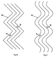
- the wave peaks 21, 31, 54 and the wave troughs 22, 32, 56 of the wave structures can have a zigzag course or a serpentine course 102 instead of a straight course have, as shown schematically in Figs. 10 and 11.
- turbulence bodies analogous to the turbulence elements 76 may be provided in the embodiment of FIG. 9.
- the zigzag-shaped and wave-shaped or wave-shaped wave structures can be formed parallel to one another (as shown) or offset in the direction of flow relative to one another.
- the spacer elements according to FIGS. 1 to 11 are made of plastic films on calenders which have corresponding surface recesses for the production of the turbulence elements 60, 76.
Landscapes
- Chemical & Material Sciences (AREA)
- Chemical Kinetics & Catalysis (AREA)
- Separation Using Semi-Permeable Membranes (AREA)
- Polyesters Or Polycarbonates (AREA)
- Transition And Organic Metals Composition Catalysts For Addition Polymerization (AREA)
- Chair Legs, Seat Parts, And Backrests (AREA)
- Control And Other Processes For Unpacking Of Materials (AREA)
Claims (10)
- Filtre moléculaire à membrane, destiné à la séparation de contaminants à faible teneur en colloïdes et de faible poids moléculaire ainsi que des ions plurivalents dans les milieux aqueux au moyen d'un élément à membrane à enroulement, où un élément écarteur ondulé qui se trouve disposé entre les couches des enroulements de la membrane est constitué par un film en matière synthétique dont la structure ondulée est décalée des deux côtés, l'une par rapport à l'autre, et dont les sommets se trouvent des deux côtés en contact avec les couches d'enroulements de la membrane, et dont les creux forment des canaux pour le passage du débit, caractérisé en ce, que des éléments de turbulence de débit (76) sont prévus pour accroître la turbulence, constitués par des projectures en forme de toit (80) disposées en succession, mais à l'écart l'une de l'autre dans le sens des canaux du débit (57, 74), et des éléments séparateurs disposés dans les creux (22, 32, 56), où les faîtages (82) sont dirigés transversalement ou sous un angle δ où 0°≤ δ ≤ 90° par rapport aux canaux de débit (74), et s'étendent d'un sommet au sommet adjacent (21, 31, 54) et dont la hauteur (H) est inférieure à la hauteur (h) des canaux de débit.
- Filtre moléculaire à membrane selon la revendication 1, caractérisé en ce, que les sommets des ondes (21, 31, 54) et les creux des ondes (22, 32, 56) des structures ondulées forment un zigzag ou ont une forme ondulatoire ou serpentine.
- Filtre moléculaire à membrane selon la revendication 2, caractérisé en ce, que les structures en zigzag ou ondulatoires, ou serpentines sont disposées parallèlement ou décalées l'une par rapport à l'autre.
- Filtre moléculaire à membrane selon la revendication 1, caractérisé en ce, que les éléments de turbulence du débit (76) en forme de toit ont des arêtes curvilignes inclinées latéralement (84, 86, 84', 86'), dirigées l'une vers l'autre et convergentes en un point (88, 88') à la base de l'onde.
- Filtre moléculaire à membrane selon la revendication 1 ou 4, caractérisé en ce, que la hauteur (H) du faîtage (82) au-dessus du niveau du fond (56, 72) est approximativement de ⅓ à ½ de la hauteur h du canal de débit (57, 74).
- Filtre moléculaire à membrane selon l'une des revendications 1 à 4, caractérisé en ce, que l'écart au faîtage A des projectures successives (80) est de 1 L à 10 L, où L est la longueur des projectures (80) entre les crêtes (88, 88').
- Filtre moléculaire à membrane selon l'une des revendications 1 à 6, caractérisé en ce, que les surfaces des toits (90, 92) des projectures (80) comprennent un angle au sommet β de 60° à 160 ° préférentiellement de 100° à 120°.
- Filtre moléculaire à membrane selon la revendication 1, caractérisé en ce, que l'angle α entre les membranes et les flancs des crêtes d'onde se situe entre 10° et 60°.
- Filtre moléculaire à membrane selon la revendication 5, caractérisé en ce, que la distance entre les couches des membranes adjacentes (4, 6) de l'élément à enroulement est égale à 2, 032 mm, la hauteur H au faîtage (82) est égale à 0,406 mm et la hauteur h du canal de débit (74) est égale à 0,975 mm.
- Filtre moléculaire à membrane selon la revendication 6, caractérisé en ce, que l'écart du faîtage A de deux projectures successives (80) est égal à 2,438 mm et la longueur L des projectures entre les crêtes (88, 88') est égale à 1,626 mm.
Applications Claiming Priority (6)
| Application Number | Priority Date | Filing Date | Title |
|---|---|---|---|
| DE10003422 | 2000-01-26 | ||
| DE10003422 | 2000-01-26 | ||
| DE10014498 | 2000-03-23 | ||
| DE10014498 | 2000-03-23 | ||
| DE10051168A DE10051168A1 (de) | 2000-01-26 | 2000-10-16 | Membrantrennvorrichtung |
| DE10051168 | 2000-10-16 |
Publications (3)
| Publication Number | Publication Date |
|---|---|
| EP1120150A2 EP1120150A2 (fr) | 2001-08-01 |
| EP1120150A3 EP1120150A3 (fr) | 2002-07-17 |
| EP1120150B1 true EP1120150B1 (fr) | 2006-02-08 |
Family
ID=27213606
Family Applications (1)
| Application Number | Title | Priority Date | Filing Date |
|---|---|---|---|
| EP00124686A Expired - Lifetime EP1120150B1 (fr) | 2000-01-26 | 2000-11-11 | Appareil de séparation à membranes |
Country Status (6)
| Country | Link |
|---|---|
| US (1) | US20020162784A1 (fr) |
| EP (1) | EP1120150B1 (fr) |
| AT (1) | ATE317287T1 (fr) |
| DE (1) | DE50012186D1 (fr) |
| HU (1) | HU0100383D0 (fr) |
| PL (1) | PL345470A1 (fr) |
Cited By (1)
| Publication number | Priority date | Publication date | Assignee | Title |
|---|---|---|---|---|
| DE202022000813U1 (de) | 2022-03-31 | 2022-04-20 | Evonik Operations Gmbh | Umgeformte Blechspacer für Spiralwickelmodule |
Families Citing this family (26)
| Publication number | Priority date | Publication date | Assignee | Title |
|---|---|---|---|---|
| US6986428B2 (en) * | 2003-05-14 | 2006-01-17 | 3M Innovative Properties Company | Fluid separation membrane module |
| NL1023742C2 (nl) * | 2003-06-25 | 2004-12-28 | Univ Twente | Afstandhouder voor toepassing in een membraanscheidingsinrichting en een membraanscheidingsinrichting die een dergelijke afstandhouder omvat. |
| DE102004017796A1 (de) * | 2004-04-05 | 2005-10-20 | Pall Corp | Abstandhalter zur Verwendung in Filtermodulen |
| EP1804959B1 (fr) | 2004-10-06 | 2014-02-26 | State of Oregon acting by and through the State Board of Higher Education on behalf of Oregon State University | Dialyseur mecs |
| US20060191837A1 (en) * | 2005-02-28 | 2006-08-31 | Alfa Laval Corporate Ab | Permeate spacer module |
| SE530221C2 (sv) * | 2005-02-28 | 2008-04-01 | Alfa Laval Corp Ab | Spirallindad membranmodul med distanselement för permeat |
| AU2006217128B2 (en) * | 2005-02-28 | 2011-08-11 | Alfa Laval Corporate Ab | Permeate spacer module |
| US20060219635A1 (en) * | 2005-03-30 | 2006-10-05 | Special Membrane Technologies, Inc. | High-density filtration module |
| DE102008031352A1 (de) * | 2008-07-02 | 2010-01-07 | Rheinisch-Westfälische Technische Hochschule Aachen | Membranvorrichtung |
| JP5616894B2 (ja) * | 2008-09-29 | 2014-10-29 | スコット・ピー・イェーガー | 螺旋巻きクロスフローフィルタ、及び流体をろ過するための方法 |
| US9452390B2 (en) | 2008-09-29 | 2016-09-27 | Scott P. Yaeger | Spiral crossflow filter |
| US8753515B2 (en) | 2009-12-05 | 2014-06-17 | Home Dialysis Plus, Ltd. | Dialysis system with ultrafiltration control |
| WO2011097403A1 (fr) * | 2010-02-04 | 2011-08-11 | Dxv Water Technologies, Llc | Systèmes et procédés de traitement de l'eau |
| DE102010010591A1 (de) * | 2010-03-08 | 2011-09-08 | Mn-Beteiligungs Gmbh | Abstandshalter für Filtrationsvorrichtungen |
| US8501009B2 (en) | 2010-06-07 | 2013-08-06 | State Of Oregon Acting By And Through The State Board Of Higher Education On Behalf Of Oregon State University | Fluid purification system |
| ES2640953T3 (es) | 2011-10-07 | 2017-11-07 | Outset Medical, Inc. | Purificación de líquido de intercambio de calor para un sistema de diálisis |
| US20130146532A1 (en) * | 2011-12-09 | 2013-06-13 | General Electric Company | Feed spacer for spiral wound membrane element |
| CN104837545B (zh) * | 2012-12-13 | 2016-10-12 | 3M创新有限公司 | 用于流体膜分离装置的构造 |
| CN103041708B (zh) * | 2012-12-28 | 2015-01-07 | 成都连接流体分离科技有限公司 | 一种高抗污染卷式膜元件 |
| JP6657186B2 (ja) | 2014-04-29 | 2020-03-04 | アウトセット・メディカル・インコーポレイテッドOutset Medical, Inc. | 透析システムおよび方法 |
| US10473010B2 (en) * | 2015-07-01 | 2019-11-12 | Mann+Hummel Gmbh | Separation element of liquid separator, separation medium, liquid separator, and method for producing separation element |
| US11325073B2 (en) | 2016-04-05 | 2022-05-10 | King Abdullah University Of Science And Technology | Fouling resistant membrane spacers |
| EP4039286A1 (fr) | 2016-08-19 | 2022-08-10 | Outset Medical, Inc. | Système et procédés de dialyse péritonéale |
| CN108176235A (zh) * | 2018-01-19 | 2018-06-19 | 南京工业大学 | 一种新构型隔网 |
| US20210394120A1 (en) | 2018-10-23 | 2021-12-23 | Politechnika Slaska | Spacer with mixing elements, particularly for membrane modules |
| US11712664B2 (en) | 2018-10-30 | 2023-08-01 | Aqua Membranes, Inc. | Flow separators for spiral wound elements |
Family Cites Families (3)
| Publication number | Priority date | Publication date | Assignee | Title |
|---|---|---|---|---|
| US3401798A (en) * | 1965-01-04 | 1968-09-17 | Dorr Oliver Inc | Cylindrically stacked and spirally configured semi-permeable membrane laminate apparatus |
| DE3005408A1 (de) * | 1979-02-15 | 1980-08-21 | Daicel Chem | Semipermeables membranelement |
| US4834881A (en) * | 1987-08-19 | 1989-05-30 | Kurita Water Industries Ltd. | Spiral wound type membrane module |
-
2000
- 2000-11-11 EP EP00124686A patent/EP1120150B1/fr not_active Expired - Lifetime
- 2000-11-11 AT AT00124686T patent/ATE317287T1/de not_active IP Right Cessation
- 2000-11-11 DE DE50012186T patent/DE50012186D1/de not_active Expired - Lifetime
-
2001
- 2001-01-25 US US09/770,596 patent/US20020162784A1/en not_active Abandoned
- 2001-01-25 PL PL01345470A patent/PL345470A1/xx not_active Application Discontinuation
- 2001-01-25 HU HU0100383A patent/HU0100383D0/hu unknown
Cited By (1)
| Publication number | Priority date | Publication date | Assignee | Title |
|---|---|---|---|---|
| DE202022000813U1 (de) | 2022-03-31 | 2022-04-20 | Evonik Operations Gmbh | Umgeformte Blechspacer für Spiralwickelmodule |
Also Published As
| Publication number | Publication date |
|---|---|
| PL345470A1 (en) | 2001-07-30 |
| EP1120150A3 (fr) | 2002-07-17 |
| ATE317287T1 (de) | 2006-02-15 |
| DE50012186D1 (de) | 2006-04-20 |
| HU0100383D0 (en) | 2001-04-28 |
| EP1120150A2 (fr) | 2001-08-01 |
| US20020162784A1 (en) | 2002-11-07 |
Similar Documents
| Publication | Publication Date | Title |
|---|---|---|
| EP1120150B1 (fr) | Appareil de séparation à membranes | |
| Judd et al. | Membranes for industrial wastewater recovery and re-use | |
| US6270671B1 (en) | Method and apparatus for microfiltration | |
| DE1642841B1 (de) | Verfahren und Vorrichtung zum Vermindern der Ionenkonzentration von Fluessigkeiten mittels umgekehrter Osmose | |
| US20040222158A1 (en) | Nanofiltration system for water softening with internally staged spiral wound modules | |
| DE1442420A1 (de) | Verfahren zum Gewinnen eines Produktes aus einer waessrigen Loesung durch umgekehrte Osmose und Vorrichtung zur Ausuebung des Verfahrens | |
| DE2529614A1 (de) | Rotationsfilterseparator vorzugsweise fuer die membranfiltration | |
| WO2007128565A2 (fr) | Unité de filtre immergé pour le traitement des eaux usées et l'obtention d'eau potable | |
| DE102006060592B3 (de) | Hybridprozess zur Meerwasserentsalzung | |
| DD296621A5 (de) | Membrantrennsystem und anwendungsverfahren | |
| WO1999067012A1 (fr) | Cartouches-filtres a contre-courant ameliorees | |
| DE2525972A1 (de) | Vorrichtung zur durchfuehrung der membranfiltration | |
| DE2513751A1 (de) | Ultrafiltrationsanlage | |
| WO2015079062A1 (fr) | Procédé et dispositif pour la filtration de liquides | |
| EP1147803B1 (fr) | Appareil de filtration et de séparation de fluides, notamment de fluides biologiques-organiques | |
| DE10004096A1 (de) | Wasseraufbereitungsanlage | |
| WO2011137990A1 (fr) | Dispositif de filtration à recyclage interne | |
| DE4300438C1 (de) | Verfahren und Vorrichtung zur Trennung von Öl/Wasser-Gemischen | |
| EP1501764B1 (fr) | Procede et installation de traitement des eaux | |
| WO2001096002A1 (fr) | Dispositif de filtration transversale de liquides | |
| EP3439770B1 (fr) | Dispositifs d'espacement de membrane résistants à l'encrassement | |
| DE2845797A1 (de) | Anisotrope, synthetische membran und verfahren zu ihrer herstellung | |
| DE10051168A1 (de) | Membrantrennvorrichtung | |
| DE10216170A1 (de) | Verfahren zur Stabilisierung und zur Steigerung von Membranleistungen | |
| EP0065490A1 (fr) | Procédé pour modifier la teneur en sels d'un liquide |
Legal Events
| Date | Code | Title | Description |
|---|---|---|---|
| PUAI | Public reference made under article 153(3) epc to a published international application that has entered the european phase |
Free format text: ORIGINAL CODE: 0009012 |
|
| AK | Designated contracting states |
Kind code of ref document: A2 Designated state(s): AT BE CH CY DE DK ES FI FR GB GR IE IT LI LU MC NL PT SE TR |
|
| AX | Request for extension of the european patent |
Free format text: AL;LT;LV;MK;RO;SI |
|
| PUAL | Search report despatched |
Free format text: ORIGINAL CODE: 0009013 |
|
| AK | Designated contracting states |
Kind code of ref document: A3 Designated state(s): AT BE CH CY DE DK ES FI FR GB GR IE IT LI LU MC NL PT SE TR |
|
| AX | Request for extension of the european patent |
Free format text: AL;LT;LV;MK;RO;SI |
|
| RIC1 | Information provided on ipc code assigned before grant |
Free format text: 7B 01D 63/10 A, 7B 01D 65/08 B |
|
| 17P | Request for examination filed |
Effective date: 20030114 |
|
| AKX | Designation fees paid |
Designated state(s): AT DE GB |
|
| 17Q | First examination report despatched |
Effective date: 20030404 |
|
| GRAP | Despatch of communication of intention to grant a patent |
Free format text: ORIGINAL CODE: EPIDOSNIGR1 |
|
| RAP1 | Party data changed (applicant data changed or rights of an application transferred) |
Owner name: UWATECH UMWELT- UND WASSERTECHNIK GMBH |
|
| 19U | Interruption of proceedings before grant |
Effective date: 20031103 |
|
| 19W | Proceedings resumed before grant after interruption of proceedings |
Effective date: 20050201 |
|
| GRAJ | Information related to disapproval of communication of intention to grant by the applicant or resumption of examination proceedings by the epo deleted |
Free format text: ORIGINAL CODE: EPIDOSDIGR1 |
|
| GRAP | Despatch of communication of intention to grant a patent |
Free format text: ORIGINAL CODE: EPIDOSNIGR1 |
|
| RAP1 | Party data changed (applicant data changed or rights of an application transferred) |
Owner name: ENVIRO-CHEMIE GMBH |
|
| GRAC | Information related to communication of intention to grant a patent modified |
Free format text: ORIGINAL CODE: EPIDOSCIGR1 |
|
| GRAS | Grant fee paid |
Free format text: ORIGINAL CODE: EPIDOSNIGR3 |
|
| GRAA | (expected) grant |
Free format text: ORIGINAL CODE: 0009210 |
|
| AK | Designated contracting states |
Kind code of ref document: B1 Designated state(s): AT DE GB |
|
| PG25 | Lapsed in a contracting state [announced via postgrant information from national office to epo] |
Ref country code: GB Free format text: LAPSE BECAUSE OF FAILURE TO SUBMIT A TRANSLATION OF THE DESCRIPTION OR TO PAY THE FEE WITHIN THE PRESCRIBED TIME-LIMIT Effective date: 20060208 |
|
| REG | Reference to a national code |
Ref country code: GB Ref legal event code: FG4D Free format text: NOT ENGLISH |
|
| REF | Corresponds to: |
Ref document number: 50012186 Country of ref document: DE Date of ref document: 20060420 Kind code of ref document: P |
|
| GBV | Gb: ep patent (uk) treated as always having been void in accordance with gb section 77(7)/1977 [no translation filed] |
Effective date: 20060208 |
|
| PLBE | No opposition filed within time limit |
Free format text: ORIGINAL CODE: 0009261 |
|
| STAA | Information on the status of an ep patent application or granted ep patent |
Free format text: STATUS: NO OPPOSITION FILED WITHIN TIME LIMIT |
|
| 26N | No opposition filed |
Effective date: 20061109 |
|
| PG25 | Lapsed in a contracting state [announced via postgrant information from national office to epo] |
Ref country code: AT Free format text: LAPSE BECAUSE OF NON-PAYMENT OF DUE FEES Effective date: 20061111 |
|
| PGFP | Annual fee paid to national office [announced via postgrant information from national office to epo] |
Ref country code: DE Payment date: 20170131 Year of fee payment: 17 |
|
| REG | Reference to a national code |
Ref country code: DE Ref legal event code: R119 Ref document number: 50012186 Country of ref document: DE |
|
| PG25 | Lapsed in a contracting state [announced via postgrant information from national office to epo] |
Ref country code: DE Free format text: LAPSE BECAUSE OF NON-PAYMENT OF DUE FEES Effective date: 20180602 |